HIT FITNESS G8 PRO User manual

HIT00698
G8 PRO INDOOR
CYCLING BIKE
USER MANUAL

CONTENTS
1.Product Brief ……………………………………………………………1
2.Safety Instructions and Warnings ……………………………..………6
3.Installation Instructions ……………………………………………..…8
4.Warm-up Suggestions …………………………………………….…….13
5.Console Function Instructions ………………………………….…..….14
6.Maintenance………………………………………………..……………17

1
1. Product Brief
Main Parameters
No.
Item
Description
No.
Item
Description
1
Power
260W
3
Max load
150kg
2
Flywheel
20kg
4
Product Size
1340*590*1310mm
Packing
List
No.
Item
Unit
Qty
No.
Item
Unit
Qty
1
Frame
pc
1
8
Saddle
pc
1
2
Console
pc
1
9
Handlebar Post
pc
1
3
Toolkit
set
1
10
Water Bottle Holder
pc
1
4
Front Stabilizer
pc
1
11
Water Bottle Holder Cover
pc
1
5
Rear Stabilizer
pc
1
12
Handlebar Post Cap
pc
1
6
Pedals
set
1
13
Adjustment Handle
pc
2
7
Seat Post
pc
1
14
Handlebar
pc
1
Toolkit
List
No.
Item
Unit
Qty
No.
Item
Unit
Qty
1
Allen Key 5mm
pc
1
6
Arc Washer T1.5*φ8.5*φ23
pc
2
2
Wrench
pc
1
7
Flat Washer φ8.5*φ16*1.5T
pc
6
3
Internal Hexagon Screw M8*16
pc
4
8
Cross Recessed Pan Head Screw
M5*20
pc
4
4
Internal Hexagon Screw M8*12
pc
4
9
User Manual
pc
1
5
Plug
pc
2
10

2
Exploded Drawing

3
PARTS LIST AND TOOLS
NO
Item
Qty
NO
Item
Qty
A
Console
1
F-3
Adjustment Handle
2
A-1
Console Cover
1
F-4
Cross Recessed Pan Head Screw
1
B
Handlebar
1
F-5
DC Cover
1
B-1
Water Bottle Holder
1
F-6
Crank Cover
2
B-2
Water Bottle Holder Cover
1
F-7
Hexagon flange nuts with glue
2
B-3
Cross Recessed Pan Head Screw
3
F-8
Left Crank Arm
1
B-4
Handlebar Post
1
F-9
C Shaped Buckle
1
B-5
Handlebar Post Plug
1
F-10
Bearing
2
C
Brake Knob
1
F-11
Handlebar Post Sleeve
1
C-1
Hexagon Nut
1
F-12
Right chain cover
1
C-2
Self-Tapping Screw
3
F-13
Sensor Bracket
1
C-3
Brake Cover
1
F-14
Crank Shaft Sleeve
1
C-4
Brake Upper sleeve
1
F-15
Lock Nut
4
C-5
Square Brake nut
1
F-16
Flat washer
4
C-6
Round Brake nut
1
F-17
Small Magnet
1
C-7
Brake Lever
1
F-18
Axis
1
C-8
Brake Lower sleeve
1
F-19
Pulley
1
C-9
Cross Recessed Pan Head Screw
2
F-20
External Hexagon Screw
4
C-10
Brake Pad
1
F-21
Left Chain Cover
1
C-11
Self-Tapping Screw
1
F-22
Right Crank Arm
1
C-12
Brake Spring Pad
1
F-23
Right Pedal
1
C-13
Brake Pad fixer
1
F-24
Left Pedal
1
D
Saddle
1
F-25
Flywheel Cover
1
D-1
Handlebar Post Plug
2
F-26
Motor Cover
1
D-2
Slider Nut
1
F-27
Belt
1
D-3
Slider
1
G
Idler Wheel
1
D-4
Seat Post
1
G-1
External Hexagon Screw
1
D-5
Flat Washer
1
G-2
Spring Washer
1
D-6
Seat Slider Adj Knob
1
G-3
Flat Washer
1
E
Rear Stabilizer
1
G-4
Lock Nut
1
E-1
Stabilizer End cap
2
G-5
Hexagon flange nuts with glue
1
E-2
Handlebar Post Cap
1
G-6
Adjuster
1
E-3
Flat washer
1
G-7
Idler Rod Axle
1
E-4
Internal Hexagon Screw
2
G-8
Wavy Washer
1
F
Frame
1
H
Gear Box
1
F-1
Seat Post Sleeve
1
H-1
Tension spring
1
F-2
Tighten Plate
2
H-2
Magnet
4

4
NO.
Item
Qty
NO.
Item
Qty
H-3
Magnet Holder Set
1
J-5
Flywheel Axle
1
H-4
Flat washer
1
J-6
Flywheel Spacer
1
H-5
Spring washer
1
J-7
Flywheel Aluminum Rim
1
H-6
External Hexagon Screw
1
J-8
Socket head cap screws
1
I
Front stabilizer
1
K-1
Sensor cable
1
I-1
Stabilizer End cap
2
K-2
Connection cable
1
I-2
Internal Hexagon Screw
2
L-1
Internal Hexagon Screw
4
I-3
Transportation wheels
2
L-2
Arc Washer
2
I-4
Flat washer
2
L-3
Flat washer
6
I-5
Lock Nut
2
L-4
Internal Hexagon Screw
4
I-6
Internal Hexagon Screw
2
L-5
Cross Recessed Pan Head
Screw
4
J
Flywheel
1
L-6
Plug
2
J-1
Hexagon flange nuts with glue
2
L-7
Allen Key 5mm
1
J-2
Flat washer
2
L-8
Wrench
1
J-3
Flywheel Bushing
1
J-4
Bearing
1

5
2. Safety Instructions andWarnings
To make sure of your safety and avoid injuries, Please read the
following instructionscarefully before using the bike and also pay attention to
the following safety warnings.
NOTE:Though the product has been thoroughly considered in terms of safety issues in its
designand production, please make sure to follow the instructions below.
We do not bear any consequences caused by improper use.
◆
This bike is suitable for indoor use. Set up and operate it on a solid level
surface. Do not place any objects on the bike.
◆
If the power cord is damaged, to avoid danger, it must be replaced by
professionals from the manufacturer, its maintenance department or related
departments.
◆
Please unplug the power plug if the product is not used for long time.
◆
When the product is not in use, please lock the flywheel to avoid injury.
◆
This product is not suitable for children. Please do not use it if you feel
unwell, otherwise it may cause injury.
◆
Handicapped or disabled persons should not use the spinning bike without
the advice of a qualified health professional or physician.
◆
Do not use the bike in a dusty room and maintain it the room to a certain
humidity. Avoid strong static electricity or it will affect the normal use of
the console. Please use the original parts, they are forbidden to be replaced
without instructions.
◆
Do not use the bike near a hot or moving object.
◆
Please unplug the bike before moving it. Non-professionals are not allowed
to disassemble the bike without authorization, otherwise serious
consequences may occur.
◆
Please make sure the garment is fastened or zippered, do not wear loose or
dangling clothing while using the bike.
◆
If you feel unwell or uncomfortable during use, please stop and consult a
physician.
◆
Use qualified sockets to avoid danger. If the plug is not compatible with the
socket, please do not touch the plug and ask an electrician to handle it.

6
◆
The product is suitable for home use, not for professional training and test,
can not be used for medical purposes.
◆
Do not use it when the shell is cracked, broken off (the internal structure
is exposed) or the welded part is cracked.
◆
Do not use immediately after eating, feeling fatigue, or not in a good
physical condition.
--It may do harm to your health.
◆
Do not scatter objects like needles, trash or water on the plug. Do not
touch the plug with wet hands.
--It may cause electric shock, short circuit, or fire.
◆
Please unplug the bike when not in use.
H A R D WA R E I D E N T I F I C AT I O N C H A R T
- - - - - - - - - - - - - - - - - - - - - - - - - - - - - - - - - - - - - - - - - - - - - - - - - - - - - - - - - - - - - - - - - - - - - - - - - - - - - - - - - - - - - -
This chart is provided to help identify the hardware used in the assembly process. Use thesmall
scale to check the length of the bolts and screws.
3. Installation Instructions
Assembly requires two persons. Place all parts of the exercise bike in a cleared area and
remove the packing materials. Do not dispose of the packing materials until assembly is completed.
NOTE:Though the product has been thoroughly considered in terms of safety issues in its design and
production, please make sure to follow the instructions below.
We do not bear any consequences caused by improper use.
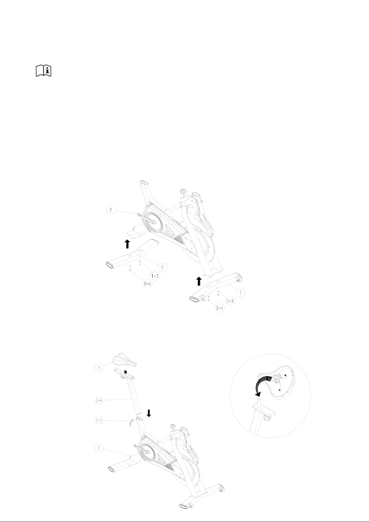
Step 1. Firstly take out the I# Front Stabilizer, E# Rear stabilizer, and L-4# Internal Hexagon Screw,L-3#
Flat washer,L-7# Allen Key (5mm) from the toolkit. Please follow the drawing below:Place both stabilizers
as below, then tighten L-4# Screws with L-7# Allen Key (5mm).
Step 2. Take out D# Saddle, D-4# Seat Post, F-3# Adjustment Handle. Please do as below: insert the Seat Post
inside the hole of the frame and tighten with the Adjustment Handle. Then place the saddle onto the slider, tighten
it at a suitable angel with L-8# Wrench. Note: Please assemble the adjustment handle after the seat post is
done.
7

Step 3. Take out the B-4# Handlebar Post , F-3# Adjustment Handle. Then remove B-5# Handlebar Post Plug.
Thread the cable inside the handlebar post and pull it out from the hole. And then pull the plug out of the A notch,
and adjust it to a suitable height. And lastly use the F-3# Adjustment Handle to lock it.
Note: Please assemble the adjustment handle after the seat post isdone.
Step 4. Take out the B# Handlebar, L-2# Arc washer, L-1# Internal Hexagon Screw M8*12 in toolkit.
Follow as below: Insert the handlebar inside the hole of the handlebar post, and then attach L-1# Screw and L-2#
Arc Washer. Lastly tighten them with L-7# Allen Key (5mm).
8

Step 5. Take out the F-23# Right Pedal, F-24# Left Pedal. Do as below: tighten them with L-8# Wrench in the
direction of the arrow.
Step 6. Take out the B-1# Water Bottle holder and B-2# Water Bottle holder cover, then remove the
pre-attached 3pcs B-3# Cross Recessed Pan Head Screw M5*14 on the handlebar. And then place the
bottle holder and the cover on the corresponding position of the handlebar in the direction shown as
below and tighten them with L-8# Wrench. The water bottle holder cover is not locked temporarily,
please reserve a gap to adjust the cable length.
9

10
III
Step 7. Take out the A# Console, A-1# Console cover, then take out the L-5# Cross Recessed Pan
Head Screw M5*20 from the toolkit. Pass the cable through the console cover in turns, and then
insert them into the slots on the back of the console, then place the console and the console cover on
the handlebar, and lastly use L-8# wrench to lock.
I
Step 8. Get two batteries(AA size) and place them into the battery slot under the console cover.
After the A# Console is on, the whole bike is completely assembled.
II

11
Please do not lock all screws tightly until you have followed all steps above to
assemble the bike. Please inspect carefully before using the bike
Handlebar/Seat Height Adjustment:
You can adjust the handlebar height and seat height with the Adjustment Handles according to your
sitting posture Note: Please don't exceed the STOP mark when adjusting the height of the
handlebar post.
Saddle Adjustment:
You can adjust the distance of the saddle with the Seat Slider Adj Knob according to your sitting
posture which can make you feel more comfortable. After adjusting to the suitable distance, use the
Seat Slider Adj Knob to tighten the saddle.
Please press STOP brake knob hard in the event of an emergency.
When the product is not in use, please rotate the brake knob clockwise to lock
the flywheel. Release the brake knob before using it next time.
12
4. Warm-up Suggestions
Warm-up and Stretching
WARM-UP
The purpose of warming up is to prepare your body for exercise and to minimize injuries. Warming
up for two to five minutes before strength training or aerobic exercising can raise your heart rate
and warm your working muscles which can also help to avoid injuries.
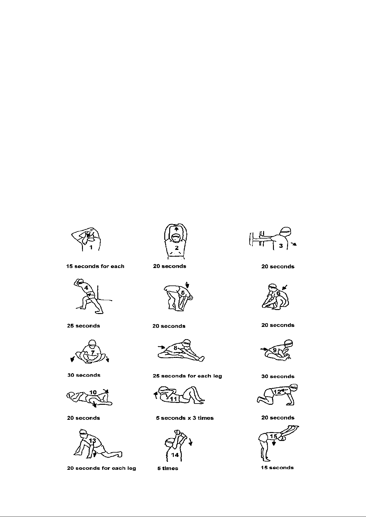
STRETCHING
Stretching is very important to warm up your muscles before exercise to avoid injuries or to relax your
muscles to relieve the soreness in muscles after strength or aerobic training. Muscles stretches are easier and
more efficient at this time because of their elevated temperature, which greatly reduces the risk ofinjury.
Each stretch should be held for 15 to 30 seconds.
Here are the suggested warm-up and stretching exercise as below.
13
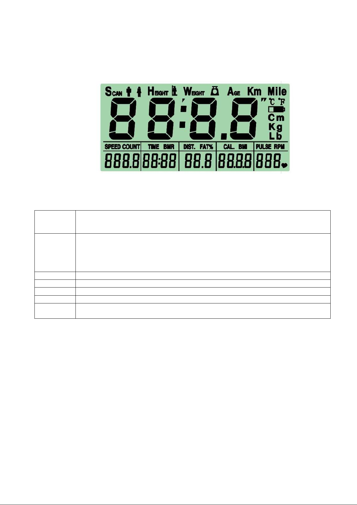
5. Console Function Instructions
I. Full Display menu
II. Button function
UP
In setting mode, to select GENDER, increase
TIME/DISTANCE/CALORIE/AGE/WEIGHT/HEIHGT;
Set the clock and alarm in clock mode;
DOWN
In settingmode, to select GENDER,decrease
TIME/DISTANCE/CALORIE/AGE/WEIGHT/HEIHGT; Set the clock and alarm in clock
mode;
Note:In setting mode, hold-on UP and DOWN button for 2 seconds, clear out set value
to “0” or restore default.
MODE
To confirm the value/selection and ENTER.
RESET
In any mode, hold on RESET for 2 seconds, the system will reboot as Total Reset.
BODY FAT
Before measuring BODY FAT, press this button to input personal data: Weight, Height..
SET
Press this button to set value of Gender, Age, Weight and Height.
RECOVER
Y
Test Heart Rate Recovery function. When press this key, system will start count down.
III. Power-on
When install batteries (2PCS AA), console will full display for one second along with “Di” sound. And
display wheel diameter for one second, and then entering Standby mode.

14
IV. Function Description
1. SCAN
After power-on, the console will auto-scan TIME/SPEED/DISTANCE/CALORIE/PULSE/RPM in
every 6 seconds, press MODE to exit auto-scan. User can press UP or DOWN button to enter manualscan
mode and set target value of TIME/DISTANCE/CALORIE/PULSE and press MODE to confirm. When
setup is completed, console will exit the manual scan and show “SCAN” for 2 seconds and then switch to
auto-scan.
2. TIME
Display the workout time when RPM signal is available (MM:SS), it will update automatically from
0:00 to 99:59 in every second. Press UP and DOWN button to set target countdown time, the buzzer will
alarm once. When it counts down to 0:00 and will display the initial set time.
3. SPEED
Display current workout speed by KM/HOUR; Display “0” if there is no signal input.
4. DISTANCE
Display accumulated workout distance, max. value is 99.9KM/MILE.
5. CALORIE
Display accumulated calorie consumption, 15Cal/KM.
6. PULSE
Display current Heart rate; Display “0” if there is no heart rate input/detected.
7. RPM
Revolutions per minute.
8. RECOVERY
Press RECOVERY button, system starts to countdown from 1:00 to 0:00. LCD display Heart Rate
recovery status
when come to 0:00. Heart Rate recovery level: F1.0~F6.0.
Note: Make sure both hands to hold on the hand grips correctly during the measuring.
1.0
means OUSTANDING
1.0<F<2.0
means EXCELLENT
2.0≦F≦2.9
means GOOD
3.0≦F≦3.9
means FAIR
4.0≦F≦5.9
means BELOW AVERAGE
6.0
means POOR

15
9. BODY FAT
9.1 Setting:
Press SET button, the screen shows MALE icon, and use UP/DOWN button to select the Gender. Press
MODE button to confirm and the screen goes to AGE setting. Use UP/DOWN button to set the number and
press MODE to enter HEIGHT setting. Use UP/DOWN to set the number and press MODE to enter
WEIGHT setting.
9.2 BODY FATTest
Press BODY FAT button, and hold on the handlebar heart rate sensor with both hands.
9.3 The display of testing result
B.F.%(BODY FAT percentage)=(1.2*BMI)+(0.23*AGE)-(10.8*SEX)-(5.4*V)
BMI(Body mass index)=WT(weight)kg/[HI(height)cm*HI]*10000
Gender: Male=1, Female=0.5
V=2-[(Measured heartbeat value-50)*0.05]
Male: BMR(Basal metabolic rate)=66+(13.7*WT)+(5*HI)-(6.8*AGE)
Female:BMR(Basal metabolic rate)=655+(9.6*WT)+(1.7*HI)-(4.7*AGE)
V. Workout and Target setting
1. Quick start:
In auto-scan mode, user can trample the machine pedal directly, console will calculate the workout data.
2. Set workout target:
In every 6 seconds, console will auto-scan TIME/SPEED/DISTANCE/CALORIE/PULSE. Press MODE to
select any function and the selected column will flash. Press UP or DOWN to set target value. After finishing,
press MODE button to go to the next function setting. (cycle setting)
3. Target exercise:
When setup any target function, trample the machine pedal directly, console will calculate the workout data
accordingly. The set target value starts counting down. When any of the target is reached, the window will
flash along with alarm sound 6 times, and then restart counting up.
4. Sleeping mode:
When console is power-off (In sleeping mode), user can trample the machine pedal directly to wake it up,
and the console will start calculating the workout data.
5. Bluetooth App Function(this function is only available with products with Bluetooth)
The product is compatible with Fitshow, Zwift and Kinomap applications. Please download the apps fromApp
Store or Google Play Store to use.
6. Chest belt Introductions
The transmitter chest belt will detect heart rate signal, and transfer the wireless signals to the receiving terminalI.e.
pulse watch, exercise computer, displaying the heart rate readout. With the low frequency for transmission and environmental-
conserved materials, the measurement is highly accurate. Water-resist design gives extra protection from sweating
during exercise.

16
Feature
1. The transmission frequency is 5.3K Hz and it is compatible with POLAR.
2. The battery willl ast for 10 month (assume to be used 1 Hour/ day)
3. Battery: 1pcs CR203
Component
A. Sensor B. Connection Belt C. Transmitter
D. Battery Housing E. Elastic Belt
How to wear the transmitter belt
Insert one end of E(Elastic Belt) into the hole of B(Connection Belt), then turn around the Elastic Belt end fitting
to the hole and press the
connection part. Wear the transmitter belt with C(sensor) closely to your chest. Then insert the other end of
E(Elastic Belt) into the other hole of B(Connection Belt). Adjust the Elastic Belt and tighten it.
Please note that the (A) position(sensor) should closely touch the right and left ventricleskin.
Remark:
You may check the following to see if you wear the transmitter belt properly
1.The transmitter shall be at a horizontal position
2.Both sensor closely shall be touching the skin of the right and left ventricle.
Battery Replacement
Using a suitable sized coin or tools, unscrew the battery cover from the transmitter
belt, fit the battery "+" sign facing upwards. Reseal the battery compartment with the cover and tighten.
Remark:
1.If the skin is in a very dry condition, the transmitter belt may not read the measurement accurately. You may
moisture par A(sensor) and retest.
2.The sensor may not detect the heart rate signal if its too hairy on the chest. Please avoid hairy position for a
more accurate reading.
6.Maintenance
Cleanliness: Comprehensive cleaning will extend the life of the spin bike.
Remove dust regularly to keep it clean. Make sure the sports shoes are clean and avoid bringing
foreign objects into the spin bike.
Maintenance: Replace the defective parts immediately or do not use the spin bike until the
defective parts are replaced. Please pay special attention to the most easily worn components.
This manual suits for next models
1
Table of contents
Other HIT FITNESS Exercise Bike manuals


Popular Exercise Bike manuals by other brands


Sunny Health & Fitness
Sunny Health & Fitness SF-B121021 user manual

Monark
Monark 827E instruction manual

Stamina
Stamina 1310 owner's manual

American Fitness
American Fitness SPR-BK1072A owner's manual
 Service manual")
Cateye
Cateye CS-1000 (CYCLO SIMULATOR) Service manual

BH FITNESS
BH FITNESS H9158H Instructions for assembly and use