manuals.online logo
Brands
  1. Home
  2. •
  3. Brands
  4. •
  5. Hitachi
  6. •
  7. Controllers
  8. •
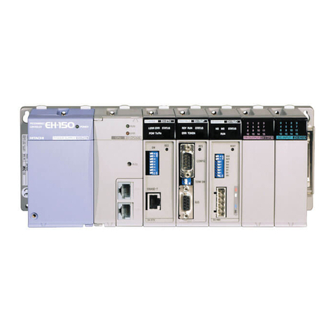
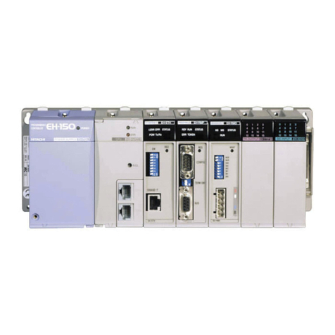
  9. Hitachi HIDIC EH-150 Instructions for use

Hitachi HIDIC EH-150 Instructions for use

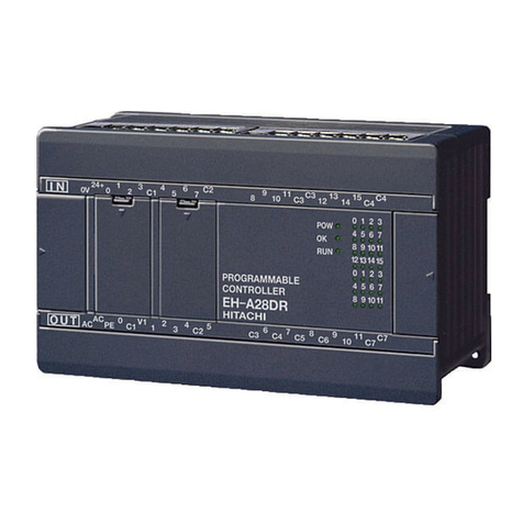
HITACHI PROGRAMMABLE CONTROLLER
1 Axis Pulse Positioning
Control Module
EH-POS
APPLICATION MANUAL
NJI-315(x)
WARNING
To ensure that the equipment described by this manual. As well as all equipment connected
to and used with it, operate satisfactorily and safety, all applicable local and national codes
that apply to installing and operating the equipment must be followed. Since codes can vary
geographically and can change with time, it is the user’s responsibility to determine which
standard and codes apply, and to comply with them.
FAILURE TO COMPLY WITH APPLICABLE CODES AND STANDARDS CAN RESULT IN
DAMAGE TO EQUIPMENT AND/OR SERIOUS INJURY TO PERSONNEL.
INSTALL EMARGENCY POWER STOP SWITCH, WHICH OPERATES INDEPENDENTLY OF
THE PROGRAMMABLE CONTROLLER TO PROTECT THE EQUIPMENT AND/OR
PERSONNEL IN CASE OF THE CONTROLLER MALFUNCTION.
Personnel who are to install and operate the equipment should carefully study this manual
and any other referred to by it prior to installation and/or operation of the equipment. Hitachi
Industrial Equipment Systems Co., Ltd. constantly strives to improve its products, and the
equipment and the manual(s) that describe it may be different from those already in your
possession.
If you have any questions regarding the installation and operation of the equipment, or if
more information is desired, contact your local Authorized Distributor or Hitachi Industrial
Equipment Systems Co., Ltd.
IMPORTANT
THIS EQUIPMENT GENERATES, USES, AND CAN RADIATE RADIO FREQUENCY
ENERGY AND, IF NOT INSTALLED AND USED IN ACCORDANCE WITH THE
INSTRUCTION MANUAL, MAY CAUSE INTERFERENCE TO RADIO COMMUNICATIONS.
AS TEMPORARILY PERMITTED BY REGULATION, IT HAS NOT BEEN TESTED FOR
COMPLIANCE WITH THE LIMITS FOR CLASS A COMPUTING DEVICES PURSUANT TO
SUBPART J OF PART 15 OF FCC ROULES, WHICH ARE DESIGNED TO PROVIDE
PEASONABLE PROTECTION AGAINST SUCH INTERFERENCE.
OPERATION OF THIS EQUIPMENT IN A RESIDENTIAL AREA IS LIKELY TO CAUSE
INTERFERENCE IN WHICH CASE THE USER, AT HIS OWN EXPENSE, WILL BE
REQUIRED TO TAKE WHATEVER MEASURES MAY BE REQUIRED TO CORRECT THE
INTERFERENCE.
LIMITED WARRANTY AND IMITATION OF LIABILITY
Hitachi Industrial Equipment Systems Co., Ltd. (Hitachi) warrants to the original purchaser
that the programmable logic controller (PLC) manufactured by Hitachi is free from defects in
material and workmanship under normal use and service. The obligation of Hitachi under this
warranty shall be limited to the repair or exchange of any part or parts which may prove
defective under normal use and service within eighteen (18) months from the date of
manufacture or twelve (12) months from the date of installation by the original purchaser
which ever occurs first, such defect to be disclosed to the satisfaction of Hitachi after
examination by Hitachi of the allegedly defective part or parts. This warranty in expressly in
lieu of all other warranties expressed or implied including the warranties of merchantability
and fitness for use and of all other obligations or liabilities and Hitachi neither assumes, nor
authorizes any other person to assume for Hitachi, any other liability in connection with the
sale of this PLC. This warranty shall not apply to this PLC or any part hereof which has been
subject to accident, negligence, alternation, abuse, or misuse. Hitachi makes no warranty
whatsoever in respect to accessories or parts not supplied by Hitachi. The term “original
purchaser”, as used in this warranty, shall be deemed to mean that person for whom the
PLC in originally installed.
In no event, whether as a result of breach of contract, warranty, tort (including negligence) or
otherwise, shall Hitachi or its suppliers be liable for any special, consequential, incidental or
penal damages including but not limited to, loss or profit or revenues, loss of use of the
products or any associated equipment, damage to associated equipment, cost of capital,
cost of substitute products, facilities, services or replacement power, down time costs, or
claims of original purchaser’s customers for such damages.
To obtain warranty service, return the product to your distributor, or send it with a description
of the problem, proof of purchase, post paid, insured, and in a suitable package to:
Quality Assurance Dept.
Hitachi Industrial Equipment Systems Co., Ltd.
46-1 Ooaza-Tomioka Nakajo-machi
Kitakanbara-gun, Niigata-ken
959-2608 JAPAN
Copyright 2002 by Hitachi Industrial Equipment Systems Co., Ltd.
All Right Reserved – Printed in Japan
The Information and/or drawing set forth in this document and all right in and to
inventions disclosed herein and patent which might be granted thereon disclosing or
employing and the materials, methods, techniques or apparatus described herein
are the exclusive property of Hitachi Industrial Equipment Systems Co., Ltd .
No copies of the information or drawings shall be made without the prior constant of
Hitachi Industrial Equipment Systems Co., Ltd.
Hitachi Industrial Equipment Systems Co., Ltd. provides customer assistance in
varied technical areas. Since Hitachi does not possess full access to data
concerning all of the uses and applications of customer’s products, responsibility is
assumed by Hitachi neither for customer product design nor for any infringement of
patents or rights of others, which may result from Hitachi assistance.
The specifications and descriptions contained in this manual were accurate at the
time they were approved for printing. Since Hitachi Industrial Equipment Systems
Co., Ltd. Incorporated constantly strives to improve all its products, we reserve the
right to make changes to equipment and/or manual at any time without notice and
without incurring any obligation other than as noted in this manual.
Hitachi Industrial Equipment Systems Co., Ltd. assumes no responsibility for errors
that may appear in this manual.
As the product works with user program, and Hitachi Industrial Equipment Systems
Co., Ltd. cannot test all combination of user program components, it is assumed
that a bug or bugs may happen unintentionally. If it is happened: please inform the
fact to Hitachi Industrial Equipment Systems Co., Ltd. or its representative. Hitachi
will try to find the reason as much as possible and inform the countermeasure when
obtained.
Nevertheless Hitachi Industrial Equipment Systems Co., Ltd. intends to make
products with enough reliability, the product has possibility to be damaged at any
time. Therefore personnel who are to install and operate the equipment have to
prepare with the countermeasure such as power off switch can be operated
independently of the controller. Otherwise, it can result in damage to equipment
and/or serious injury to personnel.
Safety Precautions
Read this manual and related documents thoroughly before installing, operating, performing preventive maintenance or performing
inspection, and be sure to use the unit correctly. Use this product after acquiring adequate knowledge of the unit, all safety
information, and all cautionary information. Also, make sure this manual enters the possession of the chief person in charge of safety
maintenance.
Safety caution items are classified as "Danger" and "Caution" in this document.
DANGER :Cases where if handled incorrectly a dangerous circumstance may be created, resulting in
possible death or severe injury.
CAUTION :Cases where if handled incorrectly a dangerous circumstance may be created, resulting in possible
minor to medium injury to the body, or only mechanical damage.
However, depending on the circumstances, items marked with may result in major accidents.
In any case, they both contain important information, so please follow them closely.
Icons for prohibited items and required items are shown below:
: Indicates prohibited items (items that may not be performed). For example, when open flames are prohibited, is shown.
: Indicates required items (items that must be performed). For example, when grounding must be performed, is
shown.
1. About installation
CAUTION
lUse this product in an environment as described in the catalogue and this document.
If this product is used in an environment subject to high temperature, high humidity, excessive dust, corrosive gases,
vibration or shock, it may result in electric shock, fire or malfunction.
lPerform installation according to this manual.
If installation is not performed adequately, it may result in dropping, malfunction or an operational error in the unit.
lDo not allow foreign objects such as wire chips to enter the unit.
They may become the cause of fire, malfunction or failure.
CAUTION
2. About wiring
REQUIRED
lAlways perform grounding (FE terminal).
If grounding is not performed, there is a risk of electric shocks and malfunctions.
CAUTION
lConnect power supply that meets rating.
If a power supply that does not meet rating is connected, fire may be caused.
lThe wiring operation should be performed by a qualified personnel.
If wiring is performed incorrectly, it may result in fire, damage, or electric shock.
3. Precautions when using the unit
DANGER
lDo not touch the terminals while the power is on.
There is risk of electric shock.
lStructure the emergency stop circuit, interlock circuit, etc. outside the programmable controller (hereinafter referred to as
PC).
Damage to the equipment or accidents may occur due to failure of the PC.
However, do not interlock the unit to external load via relay drive power supply of the relay output module.
CAUTION
lWhen performing program change, forced output, RUN, STOP, etc., while the unit is running, be sure to verify safety.
Damage to the equipment or accidents may occur due to operation error.
lSupply power according to the power-up order.
Damage to the equipment or accidents may occur due to malfunctions.
4. About preventive maintenance
DANGER
lDo not connect the , of the battery in reverse. Also, do not charge, disassemble, heat, place in fire, or short circuit the
battery.
There is a risk of explosion or fire.
PROHIBITED
lDo not disassemble or modify the unit.
These actions may result in fire, malfunction, or malfunction.
CAUTION
lTurn off the power supply before removing or attaching module/unit.
Electric shock, malfunction or failure may result.
Table of contents
Chapter 1 Introduction 1-1 to 1-3
1.1Before Use........................................................................................................................................................1-1
1.2Accessaries.......................................................................................................................................................1-2
1.3Option................................................................................................................................................................1-3
Chapter 2 Features 2-1
Chapter3 System configuration 3-1 to 3-2
3.1Structure and Parts name............................................................................................................................3-1
3.2System configuration.....................................................................................................................................3-2
Chapter 4 Function and Performance Specifications 4-1 to 4-7
4.1 General Specifications...................................................................................................................................4-1
4.2 Functional Specifications .............................................................................................................................4-2
4.3I/O Interface Specifications...........................................................................................................................4-3
4.4Input/output Signal........................................................................................................................................4-5
4.5Output Method................................................................................................................................................4-6
4.6Name of LED...................................................................................................................................................4-7
Chapter 5 Trial Run (Simple Operation Example) 5-1 to 5-6
5.1Items of Trial Run..........................................................................................................................................5-1
5.2Procedure of Trial Run...................................................................................................................................5-1
Chapter 6 Operation Data Setting 6-1 to 6-26
6.1 Operation Data...............................................................................................................................................6-1
6.1.1 Common parameter.........................................................................................................................6-1
6.1.2 Automatic Operation Position data.............................................................................................6-13
6.2 Register configuration and operation data setting.................................................................................6-20
6.2.1 I/O Allocation.....................................................................................................................................6-20
6.2.2 I/O register configuration................................................................................................................6-20
6.2.3 Status register ( Input register ) Bit Allocation........................................................................6-21
6.2.4 Control register ( Output register ) Bit Allocation....................................................................6-22
6.3Command.........................................................................................................................................................6-23
6.3.1 Control command.............................................................................................................................6-23
6.3.2 Communication command..............................................................................................................6-25
6.3.3 Display command.............................................................................................................................6-26
Chapter 7 Data Setting and Reading 7-1 to 7-5
7.1 Communication sequence.............................................................................................................................7-1
7.1.1 Setting communication flow ( communication command ) .....................................................7-1
7.1.2 Reading communication flow ( in case of Display command ) ...............................................7-2
7.2 Communication flow to change current data............................................................................................7-3
7.3 Handshake sequence.....................................................................................................................................7-4
7.3.1 Communication command..............................................................................................................7-4
7.3.2 Display command.............................................................................................................................7-4
7.3.3 Transmission matrix.......................................................................................................................7-5
Chapter 8 Operation 8-1 to 8-17
8.1 Homing Operation..........................................................................................................................................8-1
8.1.1 Desirable Homing.............................................................................................................................8-2
8.1.2 Low Speed Homing...........................................................................................................................8-2
8.1.3 High Seed Homing1 ( Off edge ).....................................................................................................8-4
8.1.4 High Seed Homing2 ( Marker stop ).............................................................................................8-7
8.1.5 Home position of Absolute Encoder..............................................................................................8-9
8.2 Manual Operation..........................................................................................................................................8-10
8.2.1 Manual Operation1 ( Control Mode by External Input ).........................................................8-10
8.2.2 Manual Operation2 ( Command Control Mode )......................................................................8-11
8.3Automatic Operation.....................................................................................................................................8-13
8.3.1 Automatic Operation1 ( One Step Operation )..........................................................................8-14
8.3.2 Automatic Operation2 ( Single cycle Operation )......................................................................8-16
8.3.3 Automatic Operation3 ( Continuous Cycle Operation )...........................................................8-17
Chapter 9 Positioning Module Installation 9-1 to 9-6
9.1 Loading the Positioning module..................................................................................................................9-1
9.2Wiring to the Power supply module............................................................................................................9-2
9.3Wiring to the Positioning module...............................................................................................................9-2
9.3.1 Output wiring....................................................................................................................................9-2
9.3.2 Caution of Input / output wiring....................................................................................................9-3
9.4Example of wiring with a Servo Amplifier................................................................................................9-4
9.4.1 Example of wiring with Hitachi AD series (increment)...........................................................9-4
9.4.2 Example of wiring with Hitachi AD series (absolute)..............................................................9-5
9.4.3 Example of wiring with YasukawaΣII series (absolute)........................................................9-6
Chapter 10 Error code list 10-1 to 10-3
Chapter 11 Trouble shooting 11-1 to 11-4
11.1 Error indication of LED.................................................................................................................................11-1
11.1.1 Trouble shooting procedure for WDTE LED on. ( Module abnormal )...................................11-2
11.1.2 Trouble shooting procedure for O.R lamp on ( Overrun error )................................................11-3
11.2 Error indication of LED.................................................................................................................................11-4
11.3Error display atPositoner ( Option )..........................................................................................................11-4
11.4Error display on EH-CPU.............................................................................................................................11-4
11.5Abnormal operation of Motor......................................................................................................................11-4
Chapter 12 Comparison with POSIT-2H 12-1 to 12-2
12.1 Comparison with POSIT-2H........................................................................................................................12-1
12.2 Command Comparison with POSIT-2H....................................................................................................12-2
Chapter 13 Programming example 13-1 to 13-11
13.1 Caution on programming..............................................................................................................................13-1
13.2 Communication program..............................................................................................................................13-1
13.3Operation program.........................................................................................................................................13-5
13.4Data readout program...................................................................................................................................13-6
13.5Example of simple program and operation...............................................................................................13-7
13.5.1 Configuration.....................................................................................................................................13-7
13.5.2 Explanation of Execution...............................................................................................................13-7
13.5.3 Program..............................................................................................................................................13-8
13.5.4 Operation example...........................................................................................................................13-11
Chapter 14 ChapterPositioner ( option ) Operation 14-1 to 14-14
14.1 Structure and operation keys.......................................................................................................................14-1
14.2 Installtion of Positioner................................................................................................................................14-2
14.3Function............................................................................................................................................................14-3
14.3.1 Mode selection...................................................................................................................................14-4
14.3.2 Monitor mode....................................................................................................................................14-5
14.3.3 Set mode.............................................................................................................................................14-6
14.3.4 Run mode............................................................................................................................................14-10
Chapter 15 Appendix 15-1 to 15-6
15.1Data Setting Sheet ( Common Parameter ).............................................................................................15-1
15.2Data Setting Sheet ( Automatic Operation Positional data )..............................................................15-2
15.3Cable for I/O connector(Option)..............................................................................................................15-3
15.4For using on the side of EH-IOCP...............................................................................................................15-4
Glossary............................................................................................................................................................15-5
Capture 1 Introduction
1-1
Chapter 1 Introduction
1.1 Before use
This instruction manual describes how properly operate the EH-POS (Positioning Control Module),
which is one of the special function module of EH-150 Programmable Logic controller (PLC).
Carefully read this manual to familiarize yourself with the procedures respectively of installation,
operation, and maintenance and inspection.
Please be sure to read the related application manual, too.
Table 1.1 Reference Manual list
item Document name Manual No.
PLC Main body EH-150 Application Manual NJI-281*(x)
Ladder Editor for Windows®V1.25 Instruction Manual
(Type:HLW-PC3) NJI-206C
Ladder Editor for Windows®V2 Instruction Manual
(Type:HLW-PC3) NJI-299
Programming
Software
Pro-H
*The lastcharacter of the manual number may be modified when the product is revised.
Cautions
lUse EH-CPU308 or EH-CPU316 for CPU module with EH-POS.
lWhen EH-CPU104 or EH-CPU208 is used, confirm ROM Version 02 or more. In this case, access
to external output area of the slot, on which high function module such as EH-POS isattached,
can not be executed by double word (DY), but it is possible by word (WY).ROM Version 01 and
less can not be used.(Please show the left side of CPU module)
lEH-POS is different from H-series positioning module POSIT-H, POSIT-2H, POSIT-A2H,POSH
in detailed specifications. To transplant an existing user program for EH-POS, readthe both
manuals carefullyand understand the difference. See theChapter 12 for the difference between
POSIT-2H (2 axis pulse positioning module) and EH-POS.
lRead thismanual carefully before using EH-POS to operate the module correctly.
lContents of the manual may be changed without notice.
Capture 1 Introduction
1-2
1.2 Accessories
The following accessories are packed in the EH-POS module. Check each item after unpacking the
module.
No. Item name Model Appearance Number
of pieces Remark
11-axis positioning
module EH-POS 1
Caution
lUse EH-CPU308 or EH-
CPU316 for CPU module
with EH-POS.
lWhen EH-CPU104 or EH-
CPU208 is used, check
ROMVersion to beVersion
02 or more. In this case,
access to external output
area of the slot, can not be
executed by double word
(DY), but it is possible by
word (WY).
Case:
10320-52F0-008
12 I/O connector
(Cable side)
Connector
(Solder type):
20 poles
10120-3000VE
1
Supplied by Sumitomo 3M
Caution
Earth the shielded of
connector and cable to solve
noise problem.
3Connector for
positioner TM8DC 1Supplied by Hirose
Electronics
NJI-326:Japanese 14 Instruction manual
NJI-326(X):English 1
Capture 1 Introduction
1-3
1.3 Option
The following options are for the EH-POS module.
No. Name Model (Spec.) Appearance Number
of pieces Remark
1Positioner RPS-3A
1st
P O S I T I O N E R
HITACHI
4
2nd
5 6
987
3
FWD REV STOP
23
1
4
0
1 2
DEL INS
CLR
MODE
CAN
CEL
STR 2nd
CONNECT THE REMOTE CABLE WITH
WWITH
CONTROLLERAFTERTURNNINGOFFTHE
INPUT POWER OF CONTROLLER
1This needs another cable for
Positioner (Item No.2).
Caution
This is not applied for CE
marking and C-TICK.
EH-POP10 (1m) 1
2Cable for positioner
EH-POP28 (2.8m) 1
Only for EH-POS
Caution
This is only for EH-POS
positioner.
EH-POC10 (1m) 1
EH-POC20 (2m) 1
3Cable for I/O
connector
EH-POC50 (5m) 1
Supplied by Sumotomo 3M.
Plug:20 pole
10120-6000EL
Case:
10320-3210-000
4Cable for servo amp (1)HITACHI AD series
(2)YASUKAWAΣII series
(3)SANYO P series
Caution
Contact sales office for
detailed information.
Soon on sale
Chapter 2 Features
2-1
Chapter 2 Features
1.Build-in continuous automatic operation function
Maximum 256 steps of Automatic operation, Continuous Automatic operation are installed.
Step operation, cycle operation, Continuous cycle operation are possible.
2. “Velocity change in Run mode”function.
EH-POS realized velocity change in RUN mode, by changing velocity data.
3.S-shaped acceleration function
At acceleration method, S-shaped acceleration mode (3 stepsacceleration mode) is added.
At setting of acceleration mode in common parameter, “trapezoid acceleration mode”or “S-shaped
acceleration mode”can be selected.
4.ABS (absolute value) encoder input
EH-POS applies for ABS (absolute value) encoder input.
At setting of “Homing mode”in common parameter, you can sethoming mode of absolute encoder.
(Applied manufacturer/series : Hitachi AD series,YasukawaΣseries/ΣII series, Sanyo Electric P
series)
5.Battery-less
EH-POS applies EEPROM as memory and realizes to back-up memory without battery. It is
rewritable up to about 100,000 times.
Preparing for frequent rewriting velocity and position data, a dedicated command is prepared.
6.Easy to use by positioner
If you do not have a programming tool, the positioner can allow you to operate “Homing operation”,
“Manual operation”, “Automatic operation”and “Teaching”. Common parameter setting or
automatic operation datasetting is available too.
Positioner can display a position and error code. Positioner is an option.
7.Ease of using position command
EH-POS supports four kinds of position command modes (pulse,µm, inch, degree).
8.Differential Line driver output method
The differential driver output is added in pulse output method. Both open collector and
differential driver are available on different output terminals.
00step, 01 to 03 step, , FF(255)Step
Distance, time
Velocity
(Example)
Continuous Cycle Operation
Distance, Time
Velocity
Trapezoid acceleration
S-shaped acceleration
(Example)
Step
Step
Distance, time
Velocity
Before changing velocity
After changing velocity
Run mode
(Example)
Chapter 3 System configuration
3-1
Chapter 3 System configuration
3.1 Structure and Parts name
Name and function Model EH-POS
Weight Approx. 0.18 kg
Dimension(mm)
1) Lock button
2) Reset switch
3)Connector for
Positioner
4) I/O connector
5) DIP switch
100
30 95
No Name Function Remarks
1) Lock button This is used when removing the module from the base unit. After it is
installed to the base unit, the fixation can be reinforced using screws. In
this case, use M4×10-mm screws.
2) Reset switch When module is abnormal, module is to be reset by pushing this switch.
3) Connector for
Positioner By connecting a positioner, setting and writing of internal data, manual
operation, automatic operation and teaching operations are available. Positioner is optional.
4) I/O connector This is connector for pulse output and external control input. Connector for cable:
SUMITOMO 3M product
Solder type:10120-3000VE
Case:10320-52F0-008
5) DIP switch Setting this switch designates the following operating modes. Even if the
switch setting is changed while the module is energizing, the operating
mode will not be changed. To switch operating modes, turn the power
off, then do the settings correctly.
Caution
When switch number 5,6 is
turned on, external overrun
signal is disable.
ON OFF Supplementary explanation
Switch No 1 2
1, 2 ON ON CW/CCW Pulse Line Output (negative)
ON OFF CW/CCW pulse Line Output (positive)
OFF ON CK/Sign Pulse Line Output (negative)
OFF OFF CK/Sign Pulse Line Output (positive)
3Not used Not used
4Ext. COIN disable Ext. COIN enable External permission Operation (When switch
number 4is turned off, it is valid.)
5Ext. +O.RUN disable Ext. +O.RUN enable External CCW overrun Operation (When switch
number 5is turned off, it is valid.)
6Ext. –O.RUN disable Ext. –O.RUN enable External CW overrun Operation (When switch
number 6is turned off, it is valid.)
Chapter 3 System configuration
3-2
3.2 System configuration
The system configuration of the EH-150 is shown below.
The EH-150 is a module-type programmable controller with the configuration shown in Figure 3.1.
1)
Power module
1)
Power module
2)
CPU module(*1) I/O module 4) Basic base
5)
Expansion unit (only when EH-CPU208/308/316)
6)
Expansion cable
7)
I/O controller
3) Positioning module,
I/O module
3) Positioning module,
Figure 3.1 EH-150 System configuration diagram
No. Device name Description of function
1) Power module Converts power supply to the power to be used within the EH-150.
2) CPU module*1 Performs operations based on the contents of the user program, receives input and
controls output.
3) I/O module*2 Positioning module, Input module, output module, analog module
4) Basic base unit*2 Base in which the power module, CPU module, I/O module, etc. are loaded.
5) Expansion base
unit Base in which the power module, I/O controller, I/O module, etc. are loaded.
6) Expansion cable Cable that connects the I/O controllers for the basic base and expansion base.
7) I/O controller Interface with expansion base and CPU module.
*1 Adopt EH-CPU308 or EH-CPU316 as CPU module with this EH-POS module. If EH-CPU104 or EH-CPU208 is
adopted as CPU module, please confirm ROM Version is 02 or more. In this case, access to external output area
of the slot, on which high function module such as EH-POS is attached, can not be executed by double word (DY),
but it is possible by word (WY). CPU module of ROM Version01 or less cannot be used with this EH-POS
module.
*2 The same type unit can be used both for the basic unit and the expansion unit.
Chapter 4Function and Performance Specifications
4-1
Chapter 4 Function and Performance
Specifications
4.1 General Specifications
The general specifications of EH-POS are shown in the table below.
Item Specification
Power requirement 5 V DC, 300 mA, 600 mA(when Positioner connected ) ,
(supplied from the programmable controller)
Operating temperature 0to 55 °Cstoring temperature –10 to 75 °C)
Operating humidity 20 to 90 % RH (no condensation), storing humidity 10 to 90 % RH (no condensation)
Operating atmosphere No presence of corrosive gases or heavy dusts
Cooling method Natural air cooling
Weight Approx. 0.18 kg
Dimension 30(W)
×
100(H)
×
95(D) mm (170(D) withI/O Connector)
External power source 5 V DC ±5% 100 mA(for pulse output) , 24 V DC 10 mA/point (for external control input)
100
30 95
(60)
(170)
15
Base unit
EH-POS
I/O
connector
Figure 4.1 Dimensions of EH-POS with I/O connector
Chapter 4Function and Performance Specifications
4-2
4.2 Functional Specifications
The function specifications of EH-POS are shown in the table below.
Item Specification
Number of controlled axes 1 axis
Maximum Speed 400k Pulse/s
Positioning Number of occupied points 256 points
data Setting method 1. Sequence program
2. Positioner (Option)
System 1. Absolute system
2. Absolute + Increment system
3. Increment system
Positioning command unit 1. Pulse
2. µm
3. inch
4. degree
Speed command Automatic, manual, homing
6.25 to 400k Pulse/s
specification with µm/s, inch/s, degree/s
Speed stage 10 stages
Acceleration and deceleration Linear acceleration and deceleration
S-shaped acceleration and deceleration (3 stage acceleration and
Deceleration)
Acc./dec.time 1 to 65,535 ms
Backlash correction 0 to 255 pulses
Range +2,147,463,647 to –2,147,463,648pulses
Pulse Output form 1. Pulse train (CW/CCW)
2. Clock + direction signal (CK/Sign)
DIP switch No.1 & No.2 decide (Output form and logic polarity).
Positioning
system
Pulse Output method 1. Open collector Output (Photo coupler isolation)
2. Differential driver Output (Photo coupler isolation)
Function of homing 1. Desirable homing
2. Low speed homing
3. High speed homing(Limit SW OFF edge)
4. High speed homing(Z or C Pulse input)
Absolute encoder AD series of HITACHI, Σ/ΣII of YASUKAWA and P series of
SANYO are available.
Teaching Available
Manual (JOG) operation Pulse output by manual input
I/O assignment Word 4W/4W
Operation of EH-POS in the CPU’s stop Enable by I/O set or a Positioner (Option)
Caution 1.Positioner is not applied for CE marking and C-TICK.
2.When the CPU is stopped in the running, the motor goes slow down and stop.
3.Maximum moving distance is 2,147,463,647 pulses in one operation. In case of the over maximum moving distance,
the motion is stopped at the maximum moving value.
4.When a power supply of EH-150 is turned off during a power supply of servo system is on, EH-POS may output some
pulses. So, please turn off the power supply of the servo system,before turning off the power supply of EH-150. And
make homingoperation after power supply is turned on in case of position control mode.
Chapter 4Function and Performance Specifications
4-3
4.3 I/O InterfaceSpecifications
I/O interface specifications of EH-POS are shown in the table below.
Items Specification
CW/CCW Pulse line Output
CK/Sign Pulse line Output
Opto-isolated open collector transistor (max.30 V DC,
30 mAResistor Load)
Opto-isolated line driver output (5 V DC)
Max. leak current 100 µA or less
Output
Max. ON drop voltage 0.8 V (at output current = 30mA)
Input voltage 10.8 to 30 V DC
Input Impedance Approx. 2.2 kΩ
Input current Approx. 10 mA(24 V DC)
Min. ON voltage 9 VOperating
Voltage Max. OFF voltage 3.6 V
ON to OFF 1 ms or lessInput delay
OFF to ON 1 ms or less
Polarity Only input of encoder signal is Plus common, others none
Input
Isolation method By photo-coupler
Chapter 4Function and Performance Specifications
4-4
1) Positioner connector (CN1): Base on RS-422
Terminal configuration Diagram of internal circuit
No. Sign signal name
1) Do−Driver output −
2) Do+ Driver output +
3) Ri−Receiver input −
4) Ri+ Receiver input +
5) 5 V DC+ +5V
6) 0 V GND
7) 0 V GND
8) 12 V DC− −12V
2) I/O connector (CN2)
Terminal configuration Diagram of internal circuit
No. Sign signal name
1) 5 V DC+
2) P5G
Eternal power
Source(pulse output)
3) CW
4) CCW Open collector
pulse output
5) CW+
6) CW−
7) CCW+
8) CCW−
Differential
pulse output
9) C+
10) C−Encoder
C-phase
11) PS−
12) PS+ Encoder
position signal
13) COIN Operation complete
14) PROG Home LS
15) +O.RUN +Over Run
16) −O.RUN −Over Run
17) MODE-
SEL Control mode Switch
18) M-CW Manual CW
19) M-CCW Manual CCW
20) 24 V DC+ External power
source (control)
8)
1)
CN1
1
8
.
.
.
.
.
.
5V
GND
-12V
GND
5V
1)
2)
4)
3)
5)
8)
7)
6)
Internal
circuit
Positioner
CN2
10
11
20
1
10)
1)
20)
11)
.
.
.
.
.
.
.
.
.
.
.
.
10),12)
9),11)
13)to19)
20)
2)
1)
3),4)
5),7)
Internal
Circuit
5V
5V
6),8)

Other manuals for HIDIC EH-150

6

Other Hitachi Controllers manuals

Hitachi HD64465 User manual

Hitachi

Hitachi HD64465 User manual

Hitachi PSC-A128WEB3 User manual

Hitachi

Hitachi PSC-A128WEB3 User manual

Hitachi Eco Compact PC-ARC-A Instruction Manual

Hitachi

Hitachi Eco Compact PC-ARC-A Instruction Manual

Hitachi MICRO EH H Series User manual

Hitachi

Hitachi MICRO EH H Series User manual

Hitachi S10mini LQS070 User manual

Hitachi

Hitachi S10mini LQS070 User manual

Hitachi H20-T Specification sheet

Hitachi

Hitachi H20-T Specification sheet

Hitachi LQZ700 User manual

Hitachi

Hitachi LQZ700 User manual

Hitachi HARC-MODBUS User manual

Hitachi

Hitachi HARC-MODBUS User manual

Hitachi PC-ARFG-E User manual

Hitachi

Hitachi PC-ARFG-E User manual

Hitachi SPX-WDC5 User manual

Hitachi

Hitachi SPX-WDC5 User manual

Hitachi HCWA10NEGQ User manual

Hitachi

Hitachi HCWA10NEGQ User manual

Hitachi PC-ARFG2-M Instruction Manual

Hitachi

Hitachi PC-ARFG2-M Instruction Manual

Hitachi HIDIC EH-150 Instructions for use

Hitachi

Hitachi HIDIC EH-150 Instructions for use

Hitachi S10VE User manual

Hitachi

Hitachi S10VE User manual

Hitachi EH-150 Series User manual

Hitachi

Hitachi EH-150 Series User manual

Hitachi ATW-YCC-03 User manual

Hitachi

Hitachi ATW-YCC-03 User manual

Hitachi HIDIC EH150 EN-TRMME Instructions for use

Hitachi

Hitachi HIDIC EH150 EN-TRMME Instructions for use

Hitachi H8/3637 User manual

Hitachi

Hitachi H8/3637 User manual

Hitachi HX-CP1S08-0 User manual

Hitachi

Hitachi HX-CP1S08-0 User manual

Hitachi HF-W100E/IoT User manual

Hitachi

Hitachi HF-W100E/IoT User manual

Hitachi PSC-A32MN User manual

Hitachi

Hitachi PSC-A32MN User manual

Hitachi FL.NET User manual

Hitachi

Hitachi FL.NET User manual

Hitachi PC-ARF1 Instruction Manual

Hitachi

Hitachi PC-ARF1 Instruction Manual

Hitachi Eco Compact PC-ARC-A User manual

Hitachi

Hitachi Eco Compact PC-ARC-A User manual

Popular Controllers manuals by other brands

Trox Technik EN 320x160 Installation operation & maintenance

Trox Technik

Trox Technik EN 320x160 Installation operation & maintenance

RKC INSTRUMENT HA400 Series instruction manual

RKC INSTRUMENT

RKC INSTRUMENT HA400 Series instruction manual

Harman AMX NETLINX NX Series Hardware reference manual

Harman

Harman AMX NETLINX NX Series Hardware reference manual

Emerson TARTARINI FL Series instruction manual

Emerson

Emerson TARTARINI FL Series instruction manual

Bornay WIND+ manual

Bornay

Bornay WIND+ manual

Forematic RIO-S installation manual

Forematic

Forematic RIO-S installation manual

KE2 Temp All-in-One Quick Start Guide

KE2

KE2 Temp All-in-One Quick Start Guide

Danfoss EKC 331 instructions

Danfoss

Danfoss EKC 331 instructions

Netafim AlphaDisc CLD quick guide

Netafim

Netafim AlphaDisc CLD quick guide

Foxun SX-VW03 operating instructions

Foxun

Foxun SX-VW03 operating instructions

AFRISO CosiTherm Series operating instructions

AFRISO

AFRISO CosiTherm Series operating instructions

Omron SYSMAC C series Reference manual

Omron

Omron SYSMAC C series Reference manual

RLE SeaHawk LD1000 quick start guide

RLE

RLE SeaHawk LD1000 quick start guide

DELTA DORE TYBOX 1010 WT user guide

DELTA DORE

DELTA DORE TYBOX 1010 WT user guide

PROEL PLCNDXPS user manual

PROEL

PROEL PLCNDXPS user manual

WOBIT MIC488 user manual

WOBIT

WOBIT MIC488 user manual

McQuay MicroTech III Installation and maintenance manual

McQuay

McQuay MicroTech III Installation and maintenance manual

Bosch REXROTH IndraMotion MLD Getting started

Bosch

Bosch REXROTH IndraMotion MLD Getting started

manuals.online logo
manuals.online logoBrands
  • About & Mission
  • Contact us
  • Privacy Policy
  • Terms and Conditions

Copyright 2025 Manuals.Online. All Rights Reserved.