manuals.online logo
Brands
  1. Home
  2. •
  3. Brands
  4. •
  5. Hitachi
  6. •
  7. Power Tools
  8. •
  9. Hitachi WR 16SE Assembly instructions

Hitachi WR 16SE Assembly instructions

PRODUCT NAME
Hitachi Impact Wrench
Model WR 16SE
LIST No.
xxx. 2014
REPAIR GUIDE ----------------------------------------------------------------------------------------------------------------- 1
1. Precautions on disassembly and reassembly------------------------------------------------------------- 1
STANDARD REPAIR TIME (UNIT) SCHEDULE ----------------------------------------------------------------------11
CONTENTS
International Sales Division
LIST No.
WR 16SE: E727
Sep. 2014
W
-1-
Fig. 1
Before attempting disassembly or reassembly, always remember to turn off the power switch and
disconnect the plug from the power source outlet.
1. Precautions on disassembly and reassembly
[Bold] numbers in the descriptions below correspond to the numbers in the Parts List and exploded
assembly diagram for the Model WR 16SE.
1. Removal of the hammer case ass’y
(1) Insert a flat-blade screwdriver into a gap between Bumper (A) [1] and the Hammer Case Ass'y [3], and
then remove Bumper (A) [1].
(2) Remove the four Bolts M5 x 35 [2]. Remove the Hammer Case Ass'y [3], Anvil (L) [6], the hammer
ass'y, and Ring Gear [19] from Housing (A).(B) Set [29].
If the Hammer Case Ass'y [3] proves difficult to remove, tap the tip of Anvil (L) [6] with a wooden
hammer to remove the Hammer Case Ass’y [3].
2. Disassembly of the impact mechanism
(1) Remove Washer (C) [20] from the hammer ass'y.
(2) Set the hammer ass'y on the J-364 washer (A) cradle (dedicated tool, Code No.334413). Press down
the tip of Spindle (A) [17] with a hand press or similar tool to compress Hammer Spring (A) [13]. During
this compression, use a small flat-blade screwdriver or similar tool to take out Stopper (A) [15], and
then release the hand press.
(3) Remove the hammer ass'y from the J-364 washer (A) cradle. Then hold the end of Spindle (A) [17]
and press the tip pawl portion of Hammer (A) [8] with a hand press or similar tool to compress Hammer
Spring (A) [13]. During this compression, use a small flat-blade screwdriver or similar tool to remove
the two Steel Balls D6.35 [7] from the cam grooves of Spindle (A) [17] and Hammer (A) [8], and
through the steel ball insertion groove.
(4) Loosen the hand press, hold Hammer (A) [8] and Washer (A) [14] together, and then pull both out from
Spindle (A) [17]. You can now take out Hammer Spring (A) [13]. Be careful not to allow any of the
twenty-nine Steel Balls D3.97 [9] to fall from the remote portion of Hammer Spring (A) [13].
SELLING POINTS
Disassembly
REPAIR GUIDE
[7]
[8]
Push.
J-364 washer (A) cradle
(
Dedicated tool
)
[14]
[17]
[13]
[15]
[17]
Hammer click
S
p
indle cam to
p
[8]
-2-
3. Removal of housing (A).(B) set
(1) Remove the eight Tapping Screws D4 x 20 [42]. You can now remove housing (B) of Housing (A).(B)
Set [29].
(2) Remove the two Tapping Screws D4 x 16 [37] and the Cord Clip [36]. You can now remove Inner
Cover (A) [23], Rotor Ass'y [25], Stator IGBT PCB [28], Controller (A) [33], Controller (B) [40], Switch
[32], and Cord [39] together.
4. Disassembly of the power supply portion
(1) Remove the four screws from the Switch [32].
(2) Use a flat-blade screwdriver or similar tool to remove silicon from the connector of the connector cable,
and then hold the connector and slowly pull it out.
Fig. 2
[28]
[34]
Connector cable
Internal wire (red)
Internal wire (black)
[32]
Flat cable
Internal wire (black)
[33]
[34]
Capacitor Internal wire (blue)
Internal wire (red)
Internal wire (blue)
[40]
Internal wire (white)
[38]
[39]
Internal wire (black)
[34]
Internal wire (black)
-3-
Fig. 3
5. Disassembly of the stator IGBT PCB, inner cover (A), and rotor
(1) Firmly hold Inner Cover (A) [23] so as not to be attracted by the magnetic force of the Rotor Ass'y [25],
and then pull out the stator of the Stator IGBT PCB [28] in direction “A” as shown below.
(2) Keep Inner Cover (A) [23] away from the fan of the Rotor Ass'y [25], use a hand press or similar tool to
press the end of the pinion of the Rotor Ass'y [25], and then remove Inner Cover (A) [23] from the
Rotor Ass'y [25].
(3) Use a small flat-blade screwdriver to remove the O-ring [24] from Inner Cover (A) [23].
A
[28]
[24]
[23]
[25]
[26]
[27]
-4-
Reverse the disassembly procedures above to reassemble the impact wrench. However, when
reassembling the impact wrench, pay particular attention to the following items.
1. Reassembly of the power supply portion and its vicinity
(1) For replacement of the Switch [32], Controller (A) [33], Controller (B) [40], and the Stator IGBT PCB
[28], connect these parts correctly with wires according to the wiring diagram.
(2) Connect the internal wires of Controller (A) [33] to the Switch [32] paying attention to the colors of the
internal wires. Then secure them with four screws as shown in Fig. 4.
(3) Note the following when connecting the connector cable to the connector of Controller (A) [33].
• Firmly connect the connector cable to the connector until it is fully seated.
• After connecting the connector cable to the connector, apply silicon adhesive (ThreeBond TB1211,
Code No. 306927) to the entire connector joint.
(4) Fully fit the internal wire and connector cable of the Stator IGBT PCB [28] into the wiring groove for
internal wires of housing (A), so that neither gets pinched.
(5) Be careful not to pinch the internal wires of Controller (A) [33].
(6) Insert the earth terminal of the Stator IGBT PCB [28] into a gap between the housing rib, screw boss,
and Stator IGBT PCB [28] as shown in Fig. 5. Be careful not to pinch the earth terminal.
Reassembly
-5-
Fig. 4
[28]
[34]
Connector cable
Internal wire (red)
Internal wire (black)
[32]
Four internal wires
Internal wire (black)
[33]
[34]
Capacitor Internal wire (blue)
Internal wire (red)
Internal wire (blue)
[40]
Internal wire (white)
[38]
[39]
Internal wire (black)
[34]
Internal wire (black)
B
Apply silicon to the entire connector joint.
View from B
Bend the terminal of the internal
wires (yellow and blue) 90°.
Internal wire (green)
Internal wire (blue)
Internal wire (black)
Internal wire (yellow)
-6-
Fig. 5
Earth terminal
[28]
Rib
[32]
Insert the earth terminal into a gap between the
housing rib, screw boss, and Stator IGBT PCB [28].
Screw boss
Push the connector cable and internal wire
into the wiring groove for internal wire.
Do not pinch the flat cable and
internal wire with the screw boss.
Push the connector cable and internal wire into
a gap between the Switch [32] and housing (A).
-7-
2. Reassembly of the impact mechanism components
(1) Mount two Washers (B) [12], Hammer Spring (A) [13], Washer (A) [14], and Spindle (A) [17] in this
order on Hammer (A) [8], which contains the twenth-nine Steel Balls D3.97 [9].
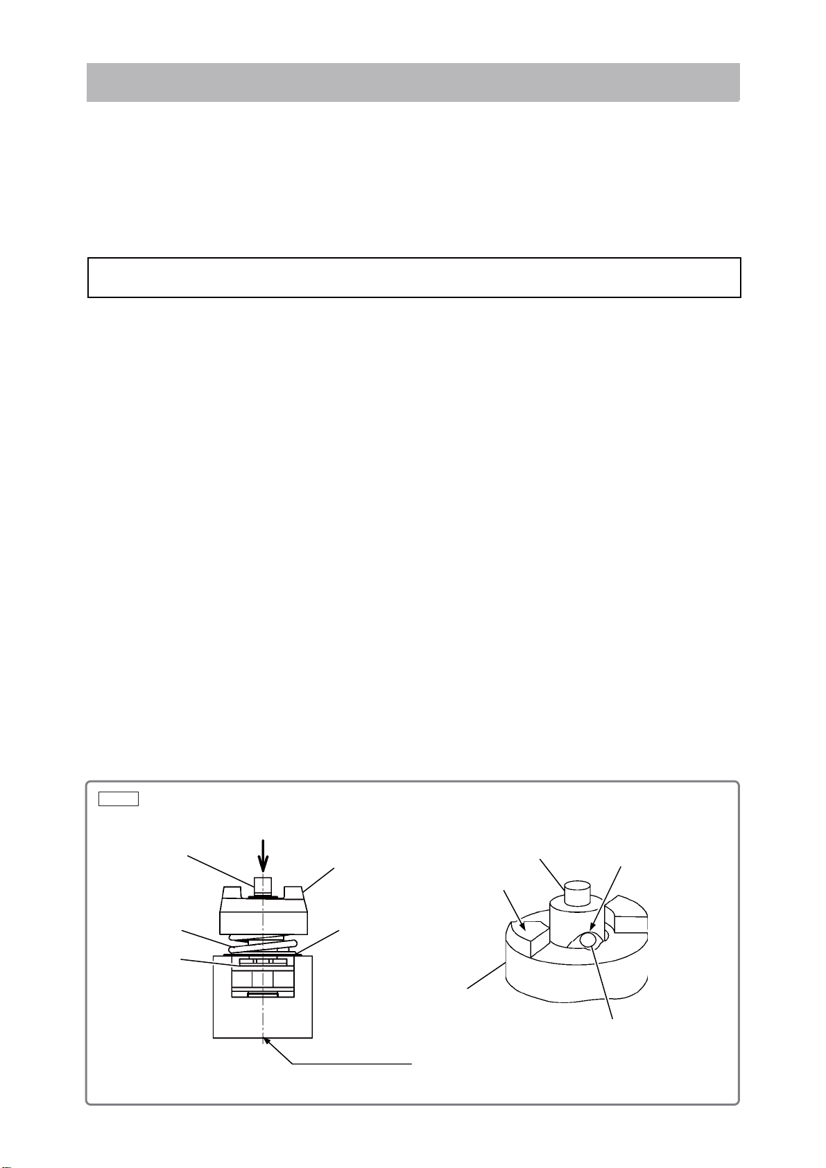
(2) Match the peak of the cam groove of Spindle (A) [17] with the steel ball insertion groove of Hammer
(A) [8]. Use a hand press or similar tool to press the end pawl portion of Hammer (A) [8] so as to
compress Hammer Spring (A) [13] until it contacts Spindle (A) [17], and then hold it there.
(3) Put the two Steel Balls D6.35 [7] in the steel ball insertion groove. Confirm that Steel Balls D6.35 [7]
are in the cam groove, and then release the hand press.
(4) Set the hammer ass’y on the J-364 washer (A) cradle (dedicated tool, Code No. 334413), use a hand
press or similar tool to press the end of Spindle (A) [17] so as to compress Hammer Spring (A) [13], fit
Stopper (A) [15] to the spindle shaft, and then release the hand press.
(5) Mount the Idle Gear Set (2 pcs.) [18] and the two Needle Rollers [16] on Spindle (A) [17].
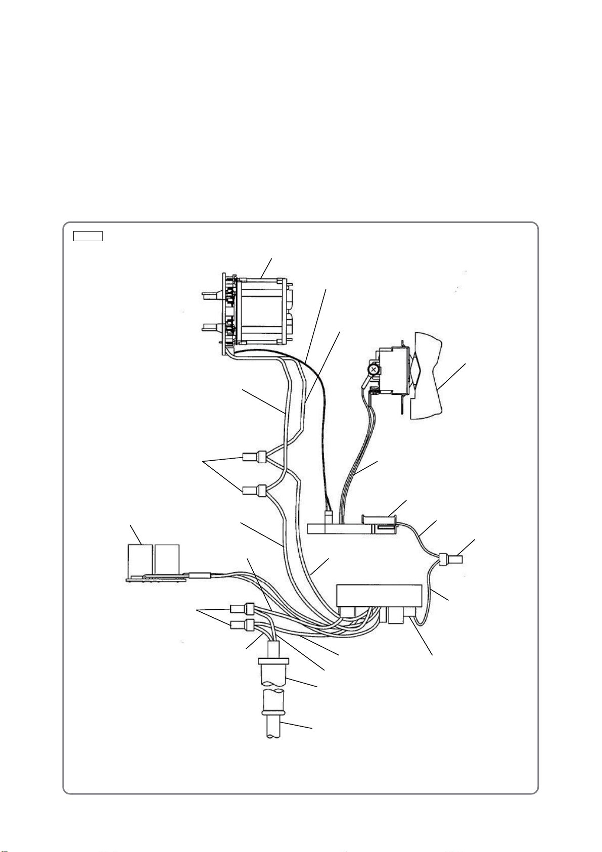
3. Reassembly of the body
(1) Mount a set comprised of Inner Cover (A) [23] (including the Rotor Ass'y [25]) and the power supply
portion to housing (A).
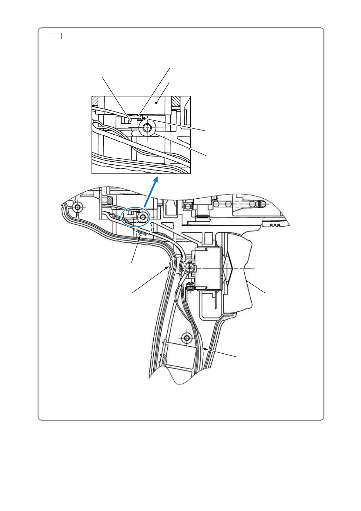
(2) Mount the Cord Clip [36] with its protrusion facing the cord, and then secure it with the two Tapping
Screws D4 x 16 [37].
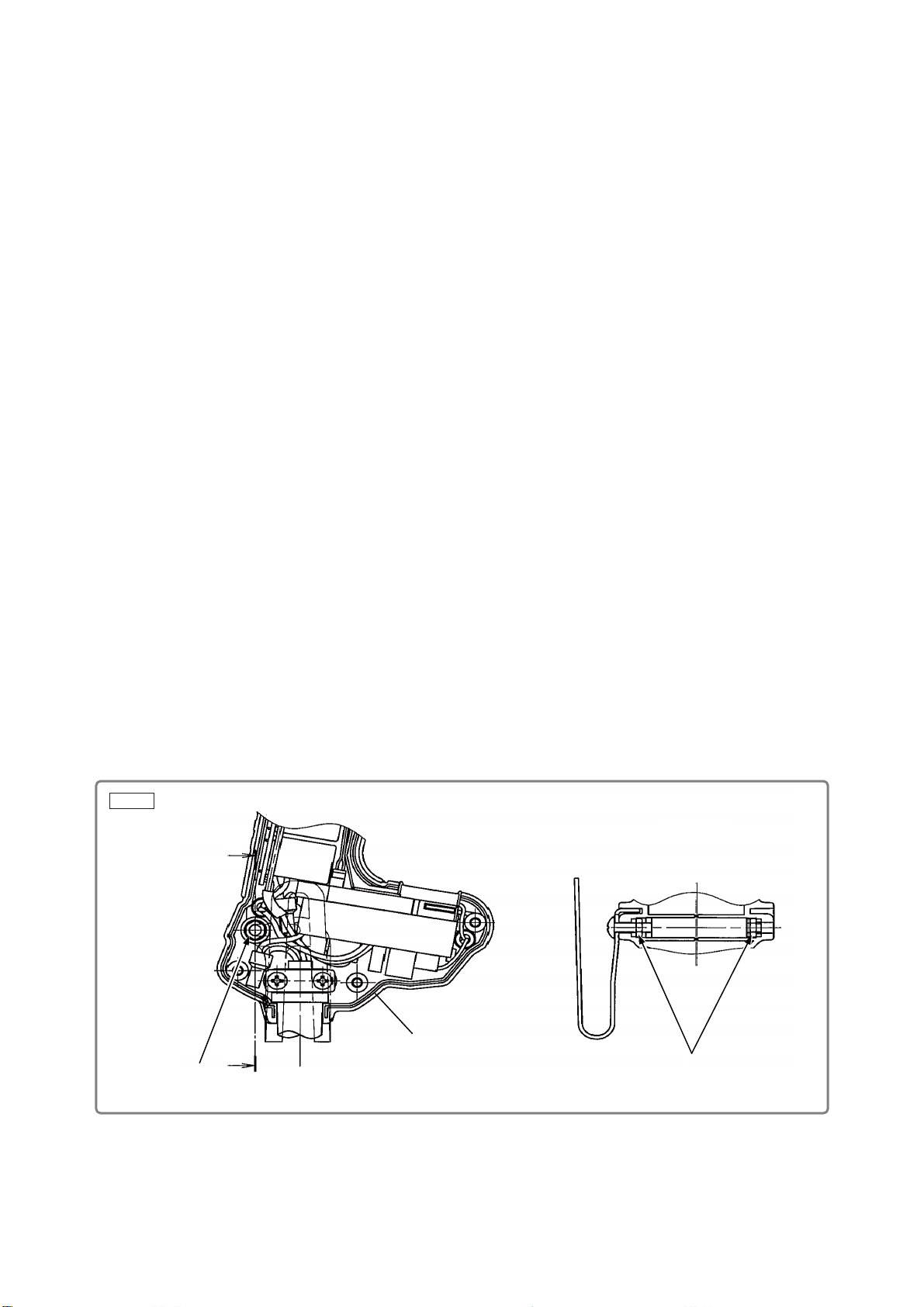
(3) Insert Lock Nut M4 [35] into Housing (A).(B) Set [29], mount housing (B), and then tighten the eight
Tapping Screws D4 x 20 [42].
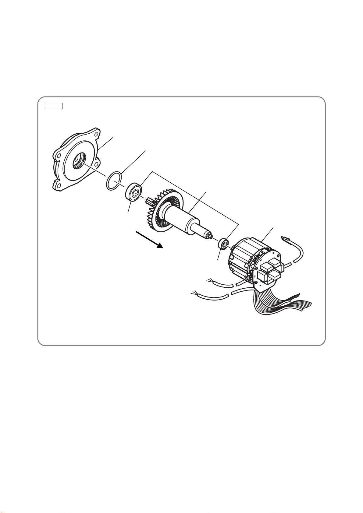
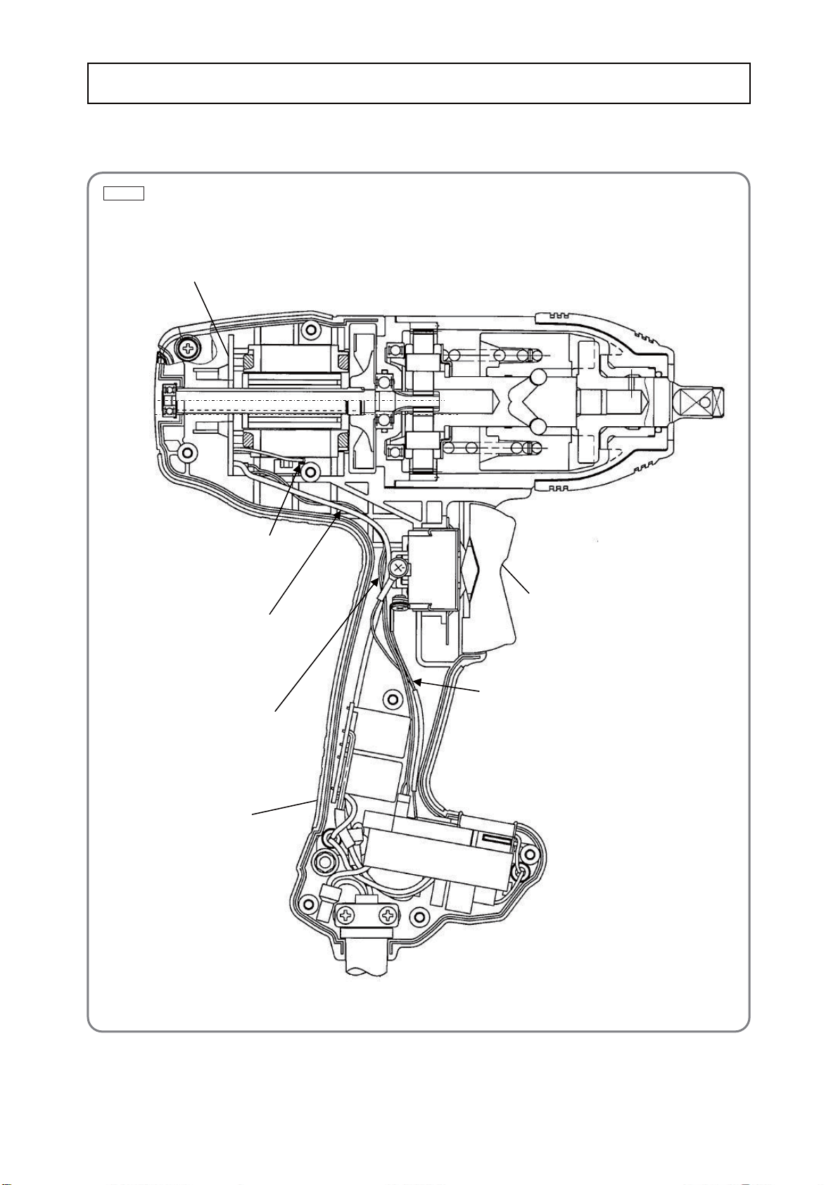
(4) Mount the hammer ass’y (reassembled in “2. Reassembly of the impact mechanism components”
above) to Housing (A).(B) Set [29], while paying attention to the engagement of the Idle Gear Set (2
pcs.) [18], Ring Gear [19], and pinion of the Rotor Ass’y [25]. At this time, the protrusion of the Ring
Gear [19] must contact the Hammer Case Ass’y [3]. Confirm that Washer (C) [20] is fitted to Spindle
(A) [17]. After reassembly, confirm that the Rotor Ass'y [25] rotates smoothly. If not, the gears may not
be properly engaged. Check and correct the gear engagement.
(5) Insert Anvil (L) [6] into the end of Spindle (A) [17] of the hammer ass’y, and then place the Hammer
Case Ass'y [3] over it. Tighten the four Bolts M5 x 35 [2]. Confirm that Packing (A) [22] is inserted
between the Hammer CaseAss’y [3] and Inner Cover (A) [23].
(6) Place Bumper (A) [1] over the Hammer Case Ass'y [3].
Fig. 6
Housing (A)
[35] C
CC - C
[35]
-8-
(1) Apply Nippeco SEP-3Agrease to the following:
•Pinion tooth flanks of the RotorAss’y [25]
•Tooth flanks of the Ring Gear [19]
•Tooth flanks and inner circumference of the Idle Gear Set (2 pcs.) [18]
•Needle Roller [16]
(2) Apply Doubrex 251 grease to the following:
•ĭ10 hole of Anvil (L) [6], metal sliding portion, and top of the pawl portion
•Steel Ball D6.35 [7]
•Metal oil groove of Hammer CaseAss'y [3]
•Hammer (A) [8] cam groove and pawl portions
•Spindle (A) [17] cam groove, sliding portion, and fitting joint withAnvil (L) [6]
•Steel Balls D3.97 [9] (29 pcs.)
•Both sides of Washer (A) [14]
•Seal Lock Hex. Socket Hd. Bolt M5 x 35 [2] ----------------------------8.82 ± 1.0 N•m (90 ± 10 kgf•cm)
•Tapping Screw (W/Flange) D4 x 20 (Black) [42]-----------------------2.45 ± 0.5 N•m (25 ± 5 kgf•cm)
•Truss Hd. Screw M4 (Black) [30] ------------------------------------------1.76 ± 0.4 N•m (18 ± 4 kgf•cm)
•Tapping Screw (W/Flange) D4 x 16 [37]---------------------------------1.96 ± 0.49 N•m (20 ± 5 kgf•cm)
Check the following after reassembly:
(1) Operate the Switch [32] and make sure that the switch moves smoothly and the switch operations (ON,
OFF, forward and reverse) are normal.
(2) Push the mode switch and confirm that the impact rate changes in four modes.
(3) Make sure the rotational direction of Anvil (L) [6] matches the direction of rotation made when you
press the Switch [32]. (When the Switch [32] is set to the (R) position, Anvil (L) [6] must rotate
clockwise as viewed from the rear (opposite to Anvil (L) [6].)
Upon completing disassembly and repair, measure the insulation resistance and conduct an insulation test
(dielectric strength test).
Insulation resistance: 7 Mȍor more with 500 V DC megohm tester
Dielectric strength: AC 2,500 V for 1 minute, with no abnormalities----- 110 to 120 V
AC 4,000 V for 1 minute, with no abnormalities----- 220 to 240 V
After no-load operation for 30 minutes, the no-load current value should be as specified below.
Voltage 110 V 120 V 220 V 230 V 240 V
Current max. 1.5 A 1.5 A 0.7 A 0.7 A 0.7 A
Screw tightening torque
Checkin
g
after
r
eassembl
y
Application of lubricant
Insulation test
No-load current
-9-
Fig. 7 • Wiring diagram
Stator IGBT PCB [28]
Carefully ensure that wiring is accomplished as illustrated below, because incorrect wiring will result in
inadequate or reverse rotation.
Wiring diagram
Push the connector cable and
internal wire into the wiring
groove for internal wires.
Be careful not to pinch the connector cable
and internal wire with the screw boss.
Switch [32]
Insert the earth terminal here
among the housing rib, screw
boss, and Stator IGBT PCB [28].
Housing (A)
Push the connector cable and
internal wire into a gap between
the Switch [32] and housing (A).
-10-
Fig. 8 • Connecting diagram
M
Stator IGBT PCB [28]
Switch [32]
Connector cable (E) 18PINFlat cable (C) 8PIN
Controller (A) [33]
Controller (B) [40]
-11-
MODEL Variable
Fixed 10 20 30 40 50 60 min.
WR 16SE
General Assembly
Work Flow
Switch
Controller
(A)
Controller
(B)
Cord
Cord Armor
Rotor Ass'y
Ball Bearing
(608DD)
Ball Bearing
(624DD)
Inner
Cover (A)
Ball Bearing
(6807)
Hammer (A)
Steel Ball
D6.35
Steel Ball
D3.97
Hammer
Spring (A)
Stopper (A)
Hammer
Case Ass’y
O-ring (M)
Anvil (L)
Ring Gear
Housing
(A).(B) Set
Stator IGBT
PCB
Spindle (A)
Idle Gear Set
Needle
Roller
STANDARD REPAIR TIME (UNIT) SCHEDULE
Model WR 16SE
IMPACT WRENCH
LIST NO. E727
2014·9·10
(E1)
6
1
23
4
5
7
8
9
12
13
14
15 16
17
18
19
20
21
22
23
24
26 25
27 28
29
30
31
32
34
34 34
33
34
35
36
37
38
39
35
40
42
501
6
10 11
41
PART
S
WR 16SE
DESCRIPTION REMARKS
1 337721 BUMPER (A) 1
2 323753 SEAL LOCK HEX. SOCKET HD. BOLT M5 X 35 4
3 337195 HAMMER CASE ASS'Y 1 INCLUD.1,4,5
4 318704 O-RING (M) 1
5 323766 METAL 1
* 6 334341 ANVIL (L) 1 TYPE FOR W/O PLUNGER(A),PIN RETAINER(A)
* 6 334342 ANVIL (L) ASS'Y 1 INCLUD.10,11 TYPE FOR W/PLUNGER (A),
PIN RETAINER (A)
7 959150 STEEL BALL D6.35 (10 PCS.) 2
8 337197 HAMMER (A) 1
9 959155 STEEL BALL D3.97 (10 PCS.) 29
* 10 323542 PIN RETAINER (A) 1 FOR FRA,FRG,ESP,ITA,RUS,USA,CAN
* 11 323541 PLUNGER (A) 1 FOR FRA,FRG,ESP,ITA,RUS,USA,CAN
12 317525 WASHER (B) 1
13 337198 HAMMER SPRING (A) 1
14 317521 WASHER (A) 1
15 337201 STOPPER (A) 1
16 985169 NEEDLE ROLLER 2
17 337196 SPINDLE (A) 1
18 323785 IDLE GEAR SET (2 PCS.) 2
19 323786 RING GEAR 1
20 337199 WASHER (C) 1
21 337733 BALL BEARING 6807 1
22 337698 PACKING (A) 1
23 337200 INNER COVER (A) 1
24 887302 O-RING (I.D 21.5) 1
25 337203 ROTOR ASS'Y 1 INCLUD.26,27
26 608DDM BALL BEARING 608DDC2PS2L 1
27 333784 BALL BEARING 624DD 1
* 28 340881 STATOR IGBT PCB 100V-120V 1
* 28 340882 STATOR IGBT PCB 220V-240V 1
29 337734 HOUSING (A).(B) SET 1
30 327001 TRUSS HD. SCREW M4 (BLACK) 1
31 335724 HOOK 1
32 337202 SWITCH 1
* 33 337700 CONTROLLER (A) 110V 1
* 33 337701 CONTROLLER (A) 120V 1
* 33 337702 CONTROLLER (A) 220V-230V 1
* 33 337703 CONTROLLER (A) 240V 1
34 959140 CONNECTOR 50091 (10 PCS.) 5
35 327002 LOCK NUT M4 (BLACK) 2
36 937631 CORD CLIP 1
37 984750 TAPPING SCREW (W/FLANGE) D4 X 16 2
* 38 953327 CORD ARMOR D8.8 1
* 38 938051 CORD ARMOR D10.1 1
* 39 500247Z CORD 1 (CORD ARMOR D8.8)
* 39 500439Z CORD 1 (CORD ARMOR D8.8) FOR AUS,NZL
* 39 500240Z CORD 1 (CORD ARMOR D8.8) FOR USA,CAN
* 39 500450Z CORD 1 (CORD ARMOR D8.8) FOR GBR (230V)
* 39 500461Z CORD 1 (CORD ARMOR D8.8) FOR GBR (110V)
- 2 - 9 - 14*ALTERNATIVE PARTS
ITEM
NO. NO.
USED
CODE NO.
PART
S
WR 16SE
DESCRIPTION REMARKS
* 39 500423Z CORD 1 (CORD ARMOR D8.8) FOR UAE (230V-240V)
* 39 500470Z CORD 1 (CORD ARMOR D8.8) FOR UAE (110V)
* 39 500201Z CORD 1 (CORD ARMOR D10.1) FOR THA
* 39 500234Z CORD 1 (CORD ARMOR D8.8) FOR VIE
* 39 500456Z CORD 1 (CORD ARMOR D8.8) FOR CHN
* 39 500435Z CORD 1 (CORD ARMOR D8.8) FOR HKG
* 40 337205 CONTROLLER (B) 100V-120V 1
* 40 337206 CONTROLLER (B) 220V-240V 1
41 NAME PLATE 1
42 301653 TAPPING SCREW (W/FLANGE) D4 X 20 (BLACK) 8
STANDARD ACCESSORIE
S
DESCRIPTION REMARKS
501 337704 CASE 1
9 - 14 - 3 -*ALTERNATIVE PARTS
NO.
USED
CODE NO.
ITEM
NO.
NO.
USED
CODE NO.
ITEM
NO. CODE NO.
OPTIONAL ACCESSORIE
S
WR 16SE
DESCRIPTION REMARKS
601 CORNER ATTACHMENT EW-14R 1 INCLUD.602-618
602 955300 HOUSING 1
603 955301 METAL 3
604 955302 SPINDLE 1
605 945251 HITACHI LABEL 1
606 955303 BEARING RACE 2
607 955304 NEEDLE THRUST BEARING (NTA-1413) 2
608 955305 COVER 1
609 955306 NEEDLE BEARING (NTN BK1012) 1
610 948227 RETAINING RING FOR D47 HOLE 1
611 955307 PINION 1
612 955308 SLEEVE 1
613 955309 WASHER 1
614 955310 SOCKET COVER 1
615 955311 SOCKET 1
616 303247 SEAL LOCK HEX. SOCKET HD. BOLT M5 X 25 6
617 873537 SOCKET PIN 1
618 873187 O-RING (J1SW1516) 1
619 986062 UNIVERSAL JOINT ASS'Y 1 INCLUD.620,621
620 873537 SOCKET PIN 1
621 873187 O-RING (J1SW1516) 1
622 873536 HEX. SOCKET ASS'Y 17MM X 32L 1 INCLUD.620,621
623 873624 HEX. SOCKET ASS'Y 19MM X 34L 1 INCLUD.620,621
624 873626 HEX. SOCKET ASS'Y 21MM X 36L 1 INCLUD.620,621
625 873627 HEX. SOCKET ASS'Y 22MM X 40L 1 INCLUD.620,621
626 873628 HEX. SOCKET ASS'Y 23MM X 40L 1 INCLUD.620,621
627 873629 HEX. SOCKET ASS'Y 24MM X 40L 1 INCLUD.620,621
628 873630 HEX. SOCKET ASS'Y 26MM X 40L 1 INCLUD.620,621
629 985195 HEX. SOCKET ASS'Y 27MM X 40L 1 INCLUD.620,621
630 985196 HEX. SOCKET ASS'Y 30MM X 50L 1 INCLUD.620,621
631 873633 EXTENSION BAR ASS'Y (SQUARE) 12.7MM X 100L 1 INCLUD.620,621
632 955138 HEX. SOCKET ASS'Y (LONG) 12MM X 52L 1 INCLUD.620,621
633 955139 HEX. SOCKET ASS'Y (LONG) 13MM X 52L 1 INCLUD.620,621
634 955140 HEX. SOCKET ASS'Y (LONG) 14MM X 52L 1 INCLUD.620,621
635 955141 HEX. SOCKET ASS'Y (LONG) 17MM X 52L 1 INCLUD.620,621
636 955142 HEX. SOCKET ASS'Y (LONG) 19MM X 52L 1 INCLUD.620,621
637 955143 HEX. SOCKET ASS'Y (LONG) 21MM X 52L 1 INCLUD.620,621
638 955144 HEX. SOCKET ASS'Y (LONG) 22MM X 52L 1 INCLUD.620,621
639 955146 HEX. SOCKET ASS'Y (LONG) 24MM X 52L 1 INCLUD.620,621
640 955149 HEX. SOCKET ASS'Y (LONG) 17MM X 75L 1 INCLUD.620,621
641 955150 HEX. SOCKET ASS'Y (LONG) 19MM X 75L 1 INCLUD.620,621
642 955151 HEX. SOCKET ASS'Y (LONG) 21MM X 75L 1 INCLUD.620,621
643 955147 HEX. SOCKET ASS'Y (LONG) 26MM X 75L 1 INCLUD.620,621
644 985197 HEX. SOCKET ASS'Y (LONG) 30MM X 75L 1 INCLUD.620,621
645 955153 UNIVERSAL JOINT PIN 1
- 4 - Printed in Japan 9 - 14
(140910N)
*ALTERNATIVE PARTS
NO.
USED
CODE NO.
ITEM
NO.

Other manuals for WR 16SE

2

Other Hitachi Power Tools manuals

Hitachi NV 45AB2 User manual

Hitachi

Hitachi NV 45AB2 User manual

Hitachi CE 16SA User manual

Hitachi

Hitachi CE 16SA User manual

Hitachi H90SE Troubleshooting guide

Hitachi

Hitachi H90SE Troubleshooting guide

Hitachi WR 14DSL User manual

Hitachi

Hitachi WR 14DSL User manual

Hitachi M 12VE Manual

Hitachi

Hitachi M 12VE Manual

Hitachi CN 16SA User manual

Hitachi

Hitachi CN 16SA User manual

Hitachi CJ 160v User manual

Hitachi

Hitachi CJ 160v User manual

Hitachi CN 16SA User manual

Hitachi

Hitachi CN 16SA User manual

Hitachi H 65SD User manual

Hitachi

Hitachi H 65SD User manual

Hitachi CJ 65V3 Manual

Hitachi

Hitachi CJ 65V3 Manual

Hitachi CM 7MR User manual

Hitachi

Hitachi CM 7MR User manual

Hitachi M 12VE Instruction Manual

Hitachi

Hitachi M 12VE Instruction Manual

Hitachi WR 12DAF User manual

Hitachi

Hitachi WR 12DAF User manual

Hitachi WM14DBL-TL User manual

Hitachi

Hitachi WM14DBL-TL User manual

Hitachi C18DLP4 - 18V Li-Ion 6-1/2" Circular Saw Troubleshooting guide

Hitachi

Hitachi C18DLP4 - 18V Li-Ion 6-1/2" Circular Saw Troubleshooting guide

Hitachi B 16RM Instruction Manual

Hitachi

Hitachi B 16RM Instruction Manual

Hitachi M 12VE User manual

Hitachi

Hitachi M 12VE User manual

Hitachi H 60MR Manual

Hitachi

Hitachi H 60MR Manual

Hitachi NV 83A2 Manual

Hitachi

Hitachi NV 83A2 Manual

Hitachi WH 18DBDL2 User manual

Hitachi

Hitachi WH 18DBDL2 User manual

Hitachi VH650 - Fencing Nailer, Full Head User manual

Hitachi

Hitachi VH650 - Fencing Nailer, Full Head User manual

Hitachi N2503AF Instruction Manual

Hitachi

Hitachi N2503AF Instruction Manual

Hitachi H 65 User manual

Hitachi

Hitachi H 65 User manual

Hitachi N 5010A Instruction Manual

Hitachi

Hitachi N 5010A Instruction Manual

Popular Power Tools manuals by other brands

Bungard CCD manual

Bungard

Bungard CCD manual

Bosch S 41 Original instructions

Bosch

Bosch S 41 Original instructions

Metabo BS 14.4 Original instructions

Metabo

Metabo BS 14.4 Original instructions

Matco Tools MT2855R manual

Matco Tools

Matco Tools MT2855R manual

Skil F0154270 SERIES Original instructions

Skil

Skil F0154270 SERIES Original instructions

Bucktool SCM4500 instruction manual

Bucktool

Bucktool SCM4500 instruction manual

Grizzly G9933 parts list

Grizzly

Grizzly G9933 parts list

Makita HK1800 instruction manual

Makita

Makita HK1800 instruction manual

Grizzly G0452Z Manual insert

Grizzly

Grizzly G0452Z Manual insert

joke FMM/3 instruction manual

joke

joke FMM/3 instruction manual

Marson BT-2 Instruction Manual for Operation

Marson

Marson BT-2 Instruction Manual for Operation

SHARKS SH 10kW Instruction for operation and maintenance

SHARKS

SHARKS SH 10kW Instruction for operation and maintenance

Gardol GAF-E 20 Li OA Original operating instructions

Gardol

Gardol GAF-E 20 Li OA Original operating instructions

Parkside PDT 40 A1 operation and safety notes original operating instructions

Parkside

Parkside PDT 40 A1 operation and safety notes original operating instructions

Beveltools Bevel Mate EBA-12 S instruction manual

Beveltools

Beveltools Bevel Mate EBA-12 S instruction manual

SUHNER LBC 16-TOP Technical document

SUHNER

SUHNER LBC 16-TOP Technical document

Sparky Group BR 9,6E instruction manual

Sparky Group

Sparky Group BR 9,6E instruction manual

Felisatti RF100/710 operating instructions

Felisatti

Felisatti RF100/710 operating instructions

manuals.online logo
manuals.online logoBrands
  • About & Mission
  • Contact us
  • Privacy Policy
  • Terms and Conditions

Copyright 2025 Manuals.Online. All Rights Reserved.