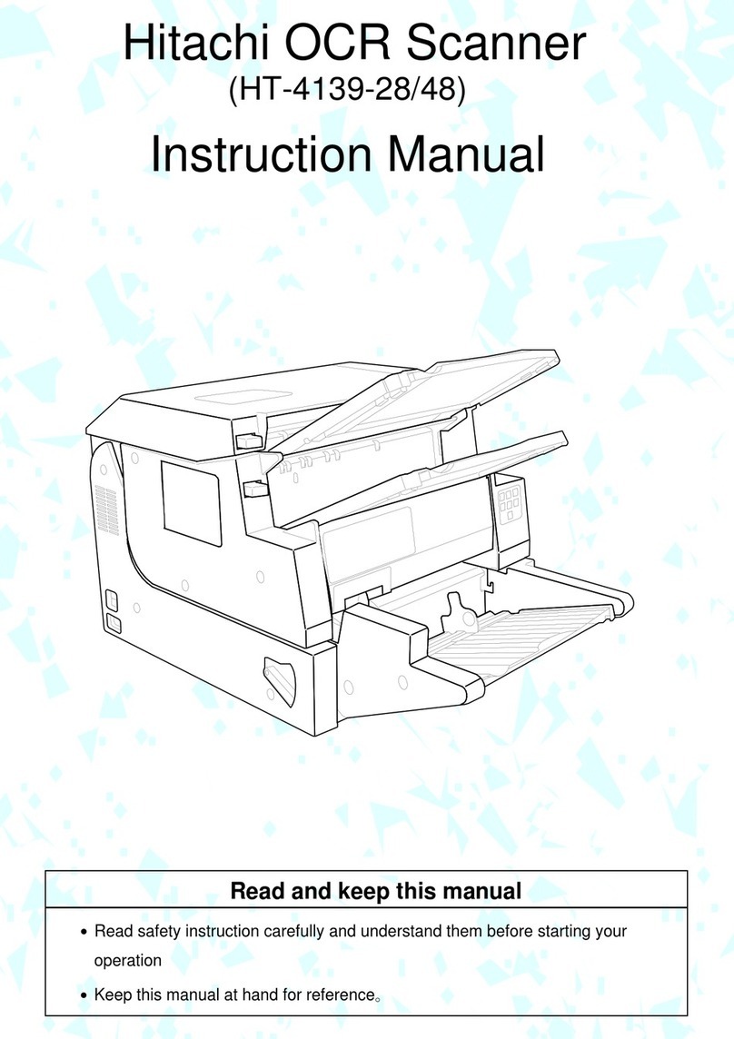
Hitachi HT-4139 User manual

Rev0
10.03.24
-G1-
HT-4139 OCR Scanner on-site Installation Manual
Contents
1. Scope.................................................................................................................................... G2
2. Tools an Parts..................................................................................................................... G2
3. Installation Time.................................................................................................................... G2
4. Proce ure ............................................................................................................................. G2
5. Installation Work ................................................................................................................... G3
5.1 Preparation ...................................................................................................................... G3
5.2 Requirement for host systems ......................................................................................... G9
5.2.1 OS, Available memory capacity of Memory an Disk................................................. G9
5.2.2 Requirement for USB ............................................................................................... G10
5.3 Installation of Image Scanner Driver .............................................................................. G11
5.4 Test Scanning ................................................................................................................ G11
5.5 Delevery......................................................................................................................... G11
5.6 Check with Data Sheet for Installation ........................................................................... G12
REVISION Control Table
REV
Date Changes
0 10.03.24
Original

Rev0
10.03.24
-G2-
1. Scope
This manual is applie to the on-site installation of OCR scanner HT-4139.
The OCR scanner HT-4139 can be operate by connecting to the PC with the USB cable.
2. Tools and Parts
(1) Stan ar Tools
(2) Circuit Tester
(3) Ethanol, Gauze
3. Installation Time
About 60 minutes
4. Procedure
Installation Work
●
Unpack the OCR scanner container an set the evice at the place where
customer specifie .
5.1
Preparation
●
Check the components, appearance, an the power supply systems.
●
Installation of the OCR scanner har ware.
NOTICE
Do not connect the USB cable to the PC.
5.2
Confirm the requirement
for the host
●
Check har ware an software of the host systems to set up the
Image Scanner
Driver.
As the OCR scanner will not work with the OS that oes not support the USB,
nee to confirm the host systems.
5.2.1
5.2.2
OS, Memory, Require
Disk Capacity
Confirm the requirement
for the USB
5.3
Installation of the Image
Scanner Driver
●
Install the Image Scanner Driver to the PC.
NOTICE
At this step. connect USB cable to the PC now.
5.4
Test Scanning
●
Ensure the OCR scanner can be operate properly by the host systems.
5.5
Delevery
●
Request the customer to confirm the installation work an explain how to operate the
evice an about safety precautions.
5.6
Check with Data Sheet for
on-site Installation
●
Ensure all work has been complete .
(Finish)
Caution
Due to the transportation in winter, there might be ew con ensation on the evice.
If you power on just after unpack an install the evice, glasses might be miste up an it may cause of rea error.
In this case, turn off the power an after a few hours power on again.

Rev0
10.03.24
-G3-
5. Installation
5.1 Preparation
Con uct items shown below.
No.
Item Proce ure
1 Components
Check their names an quantity with the attache component list.
2 Cleaning If the evice is contaminate , clean up it with gauze an ethanol.
3 Appearance Ensure there is no scratch, eformation, or iscoloration on the evice.
4 Power Supply
Require Power (Voltage): 400W(AC100V)・200W(AC200V)
Frequency: for both 50/60Hz
Earth :The thir -class level groun ing is preferable.
(Nee to confirm with customer)
5 Input Voltage
Measurement
C
H
E
Voltage shoul be measure at the power outlet.
Voltage between (H)–(C) shoul be AC90 – AC110V/ AC190 – AC240.
アース工事の確認は特に注意すること。
E: Earth, H: Hot line, C: Col line ( epen ing on countries)
6
Hopper
Attachment
(1) Peel off the tapes from the main unit an the hopper part
(2) Pushing the Main Latch Button, open the Main Cover, an remove the Mirror
Protection Sheet an Support Plate.
(cont.)
Pay particular attention to the rounding
tape
Support
Plate
tape
Support
Plate
Mirror Protection Sheet
Hopper Attaching Screw
Elevator Arm
Hopper Attaching screw
Top Cover Top Latch Button Main Latch Button
Main Cover
Si e Cover

Rev0
10.03.24
-G4-
No.
Item Proce ure
(cont.)
6
(cont.)
Hopper
Attachment
(3) Move the Elevator Arms own as shown in the picture below.
(4) Remove the Hopper Cover by removing 2 screws.
(5) Loosen the Hopper Attaching Screw at the left of the evice an attach the Hopper
ASSY. See Note below. Lift the Hopper Plate so that the Elevator Arm will be un er the
Hopper Plate.
(6) Secure the Hopper part with the screws an attach the Hopper Cover.
(7) Close the Main Cover by pushing the area of the “PUSH” labels that are both si e of
the Main cover.
Hopper Plate
Hopper attaching
Hopper Cover
Elevator Arm
NOTICE
Note:
Not loosen the Hopper Attaching Screw too
much, which causes wrong attachment with a gap
and might be a cause of glitch.
Si e View
Hopper Attaching Screw
(Loosen)
At shipment
At installation
Elevator Arm
Elevator Arm
Magnified
view
Position where
Hopper attached.
(Screw is removed)
Hopper
Correct
Correct
Wrong
Wrong
No gap
Hopper
With gap

Rev0
10.03.24
-G5-
(cont.)
No.
ITEM Proce ure
7 Stacker
Attachment
(1) Open the Top Cover by pushing the Top Latch Button.
(2) Attach the Stacker ASSY-A to the Stacker Bracket.
Secure the Stacker with attache 3 flat-hea Phillips screws.
(3) Attach the Stacker ASSY-R to the Stacker Bracket with the same proce ure as
shown
(4) Close the Top Cover
Stacker-R
Fixation Screw
Nail
Stacker-A
Stacker Bracket
(cont.)

Rev0
10.03.24
-G6-
(cont.)
No.
ITEM Proce ure
8 Stacker
Gui e
Attachment
(1) Secure the Stacker Gui e with the Stacker Gui e Fixation Screw.
Stacker Gui e
(cont.)

REV0
10.03.24
-G7-
(cont.)
No.
ITEM Proce ure
9 Position of
Imprinting
an
setting of
ribbon
cassette
(1) By pushing the Top Latch Button, open the Top Cover.
(2) Pushing the ”PUSH OPEN” label area on the Numbering (Imprinting) Cover an
open the Numbering (Imprinting) Cover.
Numbering (Imprinting) Cover
Pe estal of Ribbon Cassette
(3) Take in the slack of the Ribbon Cassette by turning the Knob on the Ribbon Cassette
to the irection of the arrow (clockwise).
Ribbon Cassette
Knob
(4) Put the Ribbon Cassette in the Numbering (Imprinting) part without catching with its
tip, an push it to the “stan ar ” position.
Tip
Numbering (Imprinting) Cover
(5) Close the Numbering (Imprinting) Cover an the Top Cover.
(cont.)
NOTE:
::
:However imprint or not the Ribbon Casette or the
Dummy Casette shoul be set.

Rev0
10.02.21
-G8-
(cont.)
No.
ITEM Proce ure
10
Cable
Connection
Connection the power cable an the USB cable.
(1) Connect the power cable that is attache to the evice to the Inlet connector that is at
the si e of the evice. The other si e shoul be connecte to the power outlet whose
voltage was measure at No. 5.
(2) Connect the USB cable to the USB connector that is at back of the evice an secure it
with the clamp that is next to it. (Lock the USB connector)
Inlet Connector
USB Connector
CAUTION:
::
:Do not turn the Power on yet
CAUTION:
::
:Do Not connect the USB cable to the PC yet

REV0
10.03.24
-G9-
5.2 Confirmation of System requirement for the host
5.2.1 OS, Available memory capacity of Memory an Disk
Prior to set up of the Image Scanner Driver, confirm the host systems meet the requirement below.
The evice installation shoul be one after setting up the host systems that satisfy the requirement.
< How to confirm >
Win ows XP
Select “start button” – “Control Panel” an ouble click “System”
Win ows Vista
Win ows7
Select “start button” – “Control Panel” an ouble click “System” & Maintenance”, click “In icate
Detaile ” button, select “Task Manager” from “Task”.
If the message box relate to the user account control, push the “CONTINUE”(C) button.
System requirement for the host
ITEM
Specifications
Check Mark
Operating Systems (OS) Win ows XP Professional SP3 Either one
Win ows Vista Business E ition SP2
Win ows Vista Enterprise E ition SP2
Win ows7 Professional E ition
PC supporte port USB2.0 Type-A port USB2.0 port*
USB2.0 Car A aptec AUA - 2000LP
A aptec USB2connect3100
If PC has no USB2.0 port,
these USB2.0 car s are
recommen e .
USB Driver Either one
Win ows XP
Win ows Vista
Win ows 7
* No guarantee of proper operation except USB2.0.
Requirement for the host systems
ITEM
Recommen e Specifications
Check Mark
Processor (CPU) Pentium 4 3.2GHz or faster Recommen e Spec.
Win ows XP
Win ows Vista
Win ows7
Main Memory Win ows XP 512Mbyte or more (for monochrome Image)
1Gbyte or more (for color image)
Win ows Vista 1Gbyte or more (for monochrome Image)
1.5Gbyte or more (for color image)
Win ows7 1.5Gbyte or more
Available Disk Volume 1 Gbyte or more
Display Resolution XGA (1024×768) or better
ATTENTION
If the host systems o not satisfy the requirement, it might cause the following problems.
●
Processor other than recommen e ················Degra ation of scanning spee or throughput
●
Main Memory
··························································Memory shortage error, other memory errors
●
Available Disk Volume
············································Unrecoverable error
Rev0
10.03.24
-G10-
5.2.2 Requirement for USB
The USB port an the USB river shoul be installe into the host systems with which set up the Image Scanner
Driver properly.
Check the following items.
No. Check Item Check Result
1 If the USB port e icate to the OCR scanner is installe ?
2 If other boar s (SCSI boar , LAN boar , etc.) are installe ?
3 If any conflict of har ware? (IRQ、I/O port a ress)
4 If the USB river is installe an work properly?
(1) Win ows XP
(1) Open Device Manager by clicking the Start
button,
clicking Control Panel, clicking System
, an then clicking
Har ware, an then clicking Device Manager.
● Points nee to be confirme
If the host controller correspon s to USB 2.0 is working
properly.
In ication sample of the host controller correspon to USB
2.0
・xxx USB Enhance Host Controller
・Stan ar Enhance PCI to USB Host Controller
・Stan ar enhance PCI to host controller
(2) Win ows Vista
(1)Open Device Manager by clicking the Start
button,
clicking Control Panel, clicking System and Maintenance,
an then clicking Device Manager.
If you are prompte for an a ministrator passwor or
confirmation, type the passwor or provi e confirmation.
●Points nee to be confirme
Check if the host controller correspon s to USB 2.0 is
working properly.
In ication sample of the host controller correspon to USB
2.0
・XXX USB Enhance Host Controller

REV0
10.03.24
-G11-
(3) Win ows 7
(1) Open Device Manager by clicking the Start
button,
clicking Control Panel, clicking Hardware and Sound
, an
then clicking Device Manager.
If you are prompte for an a ministrator passwor or
confirmation, type the passwor or provi e confirmation.
●Points nee to be confirme
Check if the host controller correspon s to USB 2.0 is
working properly.
In ication sample of the host controller correspon to USB
2.0

Rev0
10.03.24
-G12-
5.3 Installation of Image Scanner Driver
NOTICE DON'T connect the USB cable to the PC yet.
Install the Image Scanner Driver to the PC.
Refer to HT-4139 Image Scanner Driver Installation Gui e for instruction.
5.4 Test Scannig
Ask customer to test scan from the scanning application if possible.
5.5 Delivery
No.
Item Proce ure
1
Explanation
an
confirmation
to customer
(1) Report on completion of installation an request below.
(2) Before elivery, ask customer to reboot the host un er power on con ition of the
OCR scanner.
(3) If the host has customer's existing application alrea y, let the customer confirm it is
working.
(4) Ask customer to maintain the maintenance parts (Test sheets, etc.)
(5) Explain about “Safety Precautions” an ”Chapter 2 Operations” in the ”Instruction
Manual” an to let them un erstan contents.
Han s on training particularly how to han le paper jam, replacement of rollers (Pick
roller, Separator roller, Reverse roller)

REV0
10.03.24
-G13-
5.6 Check with Confirmation Data Sheet for Installation
With the checklist below, ensure all work has been complete .
Item Content Check Result
Installation Unpacking an checking the evice
Preparation Components, Appearance, Cleaning
Check power supply systems
Measurement of Input voltage
Hopper Attachment
Stacker/Stacker Gui e Attachment
Position of Imprinting an setting of ribbon cassette
Cable Connection
OS, Available memory capacity of Memory an Disk
Requirement for host
systems USB river
Installation of Image Scanner
Driver
Setting up of the Image Scanner Driver
Test Scanning Test scan from customers scanning application
Delivery (1) Reboot
(2) Check customer's existing
application
(1) Completion
Report
(3) Maintenance Parts
(1) Power On/Off
(2) Open/Close Top Cover
(3) Scanning Sheets
(4) Fixing paper jam
(5) Roller Replacement
(Pick, Separator, Reverse)
(2) Explanation
of Operation to
Customer
(6) Daily Maintenance
Table of contents
Other Hitachi Scanner manuals

Hitachi
Hitachi HT-4139-28 User manual

Hitachi
Hitachi HT-4139-28 Programming manual

Hitachi
Hitachi HT-4139-48 User manual

Hitachi
Hitachi HT-4139-28 Instruction Manual

Hitachi
Hitachi EUB-5500 Quick start guide

Hitachi
Hitachi Printers User manual

Hitachi
Hitachi EUP-S70 User manual

Hitachi
Hitachi ASU-1014 User manual