HITROL HLT-1110 Series User manual

HLT-1110 Series
HITROL CO., LTD. 1
Doc. no. : HLT1110_IM_Eng_Rev. 3
Issue date : 2021. 02
HITROL CO., LTD.
HEAD OFFICE.FACTORY.R&D INSTITUDE
HITROL CO., LTD. 141, Palhakgol-gil, Jori-eup
Paju-si, Gyeonggi-do, Korea
TEL. : (+82)-31-950-9700
FAX. : (+82)-31-943-5600
www.hitrol.com
INSTRUCTION MANUAL
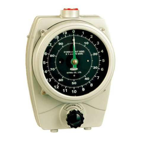
TANK LEVEL GAUGE
HLT-1110 Series

HLT-1110 Series
HITROL CO., LTD. 2
You should be careful where CAUTION is marked to carry
outthework.
You should be well-informed of the contents where
WARNING is marked before carrying out the work.
.
You should be aware of where NOTICE is marked to carry
outthework.
Table of Contents
Overview.................................................................3
Operating Principles .............................................3
Characteristics............................................................3
Specification............................................................4
Product Configuration and Technical Data ................ 4
HLT-1110 Series for Cone Roof Tank......................... 4
HLT-1110 Series for Underground Tank................... 5
HLT-1110 Series for floating Tank ............................... 6
HLT-1110 Series for with U-Seal Pot ......................... 7
HLT-1110 Series for with Guide Pipe......................... 8
Installation............................................................12
Conditions for Installation and Adjustment .........12
Installation Sequence.......................................................12
Installation Summary .......................................................17
Precautions for Installation ..................................17
Gauge Operation.................................................19
Maintenance...........................................................20
Other Precautions..................................................20
Marking.................................................................20
Model Notation...................................................20
Warranty and Contact Information.......................20

HLT-1110 Series
HITROL CO., LTD. 3
The HLT-1110 Series level gauge is an instrument used to measure the level of fluid stored in the tank
using a spring as the float moves. It can be used in a variety of industries such as crude oil, oil refining,
petrochemicals, food industries, power plants, and water treatment.
It consists of a measuring tape and a gauge head connected to the float. The float floats on the liquid
surface in the tank as sinking until the point where the weight of the float and the buoyancy of the
float are balanced. When the float is submerged, it is balanced by its own buoyancy and tension on
the measuring tape. The measuring tape is wound to a tape drum located inside the tank gauge head
and transmits tension to a spring drum. This instrument uses a spring to measure the level of fluid
stored in the tank as the float moves.
■Gauge using spring balance which can be read in [mm]
■No power required
■Checking the operation of the gauge by an operating checker
■Can be installed in a variety of tanks (e.g. Fixed Roof, Spherical Tank)
■Can be read on the ground or at the tank
■Additional function of transmitters for remote instruction, control, and alarm
■Suitable for corrosive and toxic fluids
Guide wire
Float
Measuring tape
Indicator
Tape drum
Spring loaded
drum (larger)
Spring loaded
drum (smaller)
Reduction gear
Sheave elbow
Sprocket
Float holder
Overview
Operating
Principles
Characteristics

HLT-1110 Series
HITROL CO., LTD. 4
Gauge head
Gauge support
[UserScope]
Pipe
PT1-1/2”(40A)
Pipe support
Sheave Elbow
Measuring tape
Float
Bottom anchor
Guide wire
Top anchor
Nozzle socket
PT1”(25A)
[UserScope]
[UserScope]
Nozzle socket
PT1-1/2”(40A)
Specification
Product
Configuration
and Technical
Data
Type
Screw Type: HLT-1110
Flange Type: HLT-1210
Installation
Top or Side mounting
Indicator
2-point dial
Ambient Temp.
-20℃~ 60℃
Fluid Temp.
Max. 150℃
Operation Press.
ATM
Enclosure
Weather-proof (IP65)
Applications
Liquid
Gauge Range [m]
2.5 / 5 / 10 / 16 / 20 / 30
Specific Gravity
0.6 ~ 2.0
Accuracy
Up to ±0.05% of F.S
Combination Transmitter
HAT Series
Process Conn. Size
Screw Type: PT 1-1/2”(F) Socket (Std.)
Flange Type: 1-1/2”(40A) Flange (Std.)
■HLT-1110 Series for Cone Roof Tank

HLT-1110 Series
HITROL CO., LTD. 5
Float
Bottom anchor
Guide wire
Measuring tape
Top anchor
[User Scope]
Nozzle socket
PT1-1/2”(40A)
[UserScope]
Nozzle socket
PT1”(25A)
[UserScope]
Pipe
PT1-1/2”(40A)
Gauge head
Gauge support
[User Scope]
Stanchion Pipe
■HLT-1110 Series for Underground Tank

HLT-1110 Series
HITROL CO., LTD. 6
Measuring tape
Measuring wire
Gauge head
Gauge support
Pipe support
Measuring tape
[UserScope]
Pipe
PT1-1/2”(40A)
90°Elbow
Floating tank
Float
Measuring wire
■HLT-1110 Series for floating Tank

HLT-1110 Series
HITROL CO., LTD. 7
Float
[UserScope]
Pipe
PT1-1/2”(40A)
Pipe support
Gauge head
Gauge support
Sheave elbow
[UserScope]
Nozzle socket
PT1”(25A)
Top anchor
[UserScope]
Nozzle socket
PT1-1/2”(40A)
Bottom anchor
Guide wire
Measuring tape
U-Seal pot
Sealing liquid is a customer scope because it cannot be shipped to site due to policy for
dangerous object of Air and/or Sea international transportation.
(Non-evaporating liquids, i.e. Silicone Oil, Spindle Oil, Paraffin Oil, etc. are recommended.)
■HLT-1110 Series for with U-Seal Pot

HLT-1110 Series
HITROL CO., LTD. 8
[UserScope]
Pipe
PT1-1/2”(40A)
Pipe support
Gauge head
Gauge support
Sheave elbow
Flange (150A)
[UserScope]
Guide pipe (150A)
[UserScope]
Measuring tape
[UserScope]
Nozzle socket
PT1-1/2”(40A)
Float
■HLT-1110 Series for with Guide Pipe

HLT-1110 Series
HITROL CO., LTD. 9
■ Part Name and Dimensions
The dimensions on the following pages are indicated in [mm]
[Gauge head]

HLT-1110 Series
HITROL CO., LTD. 10
[Part]
Sheave elbow (AL) Sheave elbow (SUS)
Gauge support
Top anchor
Pipe support U-bolt

HLT-1110 Series
HITROL CO., LTD. 11
Bottom anchor
Float
U-seal pot (CS+AL) U-seal pot (SUS)

HLT-1110 Series
HITROL CO., LTD. 12
1) Make sure that the pipes and bottom anchor are ready.
2) It doesn’t matter if you install the pipes and Sheave elbow first.
3) The inside of the tank should be empty and there should be no interference in instrument installation.
4) The nozzle of the tank should be installed in accordance with the connections and specifications of our
instruments and should not pose any risk of internal operation.
5) Install the gauge head in a position that is easily visible. (e.g. approximately 1500mm from the ground.)
6) There should be no fluid leaks.
7) The environment should be in place to ensure that installation and adjustment can be performed safely.
8) If used in toxic gases, the U-Seal pot should be used as there is a concern of product damage.
2.1 Guide wire Installation
1) Open the cover of the top anchor at the top of the tank.
2) Insert the guide wire from the top anchor and tighten it with a nut①and nut②to secure it to
the top anchor, giving a margin of at the end of the guide wire approximately 100mm. [Refer
to Figure.1-a]
3) Insert the guide wire into the guide ring of the float at the bottom of the tank and secure the
guide wire to the bottom anchor using bolts and nuts. [Refer to Figure.1-b]
4) Cut and bend the end of the guide wire to prevent the float being caught.
5) Tighten Nut③to adjust the tension of the guide wire. [Refer to Figure.1-c]
Nut ①
Nut ②
Nut ①
Nut ②
Nut ③
[Fig. 1-a]
[Fig. 1-b]
[Fig. 1-c]
[Figure. 1] Guide Wire Installation
Installation
1. Conditions for Installation and Adjustment
2. Installation Sequence

HLT-1110 Series
HITROL CO., LTD. 13
[Figure. 2] Measuring Tape Installation (1)
Elbow-B (Gauge Side)
Elbow-A (Tank Side)
Elbow-B (Gauge Side)
Elbow-A (Tank Side)
Measuring tape
[Figure. 3] Measuring Tape Installation (2)
2.2 Measuring Tape Installation
2.2.1 Installation Sequence of Measuring Tape (Head Part)
1) Insert the measuring tape into the sheave elbow.
①Uncover both Elbow-A and Elbow-B. [Refer to Figure.2]
▶At this point, elbows and pipes should be installed first.
②Pass the measuring tape in the direction A at Elbow-B. [Refer to Figure.3]
▶Install the measuring tape with holes in the direction of the gauge head (Outside the tank).
▶Be sure that the hole processing boundary marked on the measuring tape is located
between Elbow-A and B.

HLT-1110 Series
HITROL CO., LTD. 14
2) Install the measuring tape to the gauge head.
①Open the back cover of the head.
②Pull the measuring tape out of the upper elbow through the hole in the connection
section above the gauge head downwards.
③Align the measuring tape well between the sprocket groove and the tape guide.
▶Make sure that not to allow the tape to deviate from the sprocket.
▶At this point, the sprocket and tape guide intervals are adjusted by means of a screw. [Refer to Figure.4]
④Bolt the tape to the tape locking screw on the tape drum. [Refer to Figure.5]
▶However, the part without holes of the tape should not be allowed into the head.
▶Refer to [Table. 1] for measuring tape supply length.
[Figure. 4] Measuring Tape Installation (3)
[Figure. 5] Measuring Tape Installation (4)
[Table. 1] Measuring Tape Supply Length.
▶The supply length of the measuring tape is twice the length of the scale range, plus the extra (6m).
e.g. When the scale range is 10m, the length of the measuring tape supply length is 26m.
▶Drill holes so that the scale range + 6m can be wound into the sprocket.
e.g. When the scale range is 10m, the length of the part of the holes of the measuring tape is 16m.
▶Depending on the on-site scale range, the supplied measuring tape can only cut the clearance
length in the area where the holes are not machined.
▶The measuring tape (with holes) connected to the head should never be cut.
Scale Range [m]
2.5
5
10
16
20
30
Measuring Tape Supply Length [m]
11
16
26
38
46
66

HLT-1110 Series
HITROL CO., LTD. 15
2.2.2 Installation Sequence of Measuring Tape (Float Part)
1) Fold the end of the measuring tape on side Elbow-A in order ① to ⑥ and connect it to the
float. [Refer to Figure.6]
① Fold the end of the measuring tape about 60~70mm.
② Fold the measuring tape again.
③ Fold the center of the measuring tape.
④ Make sure that it is folded properly.
⑤ Insert the folded measuring tape into the joint shaft.
⑥ Insert the tape clamp into the measuring tape loop and secure it with a bolt and nut.
▶At this point, use a bolt that is not longer than 10mm.
②
Bending
①
④
③
Bending
[Figure. 6] Measuring Tape Installation (5)
Tape Clamp
⑥
⑤
Joint Shaft
※ Measuring Tape and Float Part Installation Cautions
▶Make sure that the tape is secured temporary from the top of the
sheave elbow to prevent it from falling out. (Fixed to the site situation).
▶Depending on the scale range, cut the remaining tape after
installation by using a metal cutting snips.
▶When folding the measuring tape, take care not to bend it.

HLT-1110 Series
HITROL CO., LTD. 16
2.3 Spring Installation
1) Secure the measuring tape to the tape drum using a tape locking screw, then turn the tape drum counter-
clockwise to wind the measuring tape so that the float is placed on the top of the tank. [Refer to Figure.7]
2) Bolt the spring on the spring loaded drum① onto the spring locking screw on the spring loaded drum②.
[Refer to Figure.8-1]
▶At this point, you should place the spring locking screw to the right side of you because the spring
will be wound in a clockwise. [Refer to Figure.8-2]
3) Wind about 2~3 turns clockwise to prevent the fixed spring from escaping.
4) After wind the spring, bolt the spring loaded drum② into the tape locking screw on the tape drum.
5) After that, fasten the spring loaded drum with the stop ring at the top of the axis to finish.
▶Fix both spring loaded drum① and ②.
※To Inspect Assembly
▶If both the measuring tape and the spring are installed, move the float which outside the head
to make sure that the measuring tape is not jammed or dislodged.
▶At this point, when the spring is wound, the tape is untangled.
▶In addition, if the tape is pulled and there is a jam or break, fine-tune it with the screw on the tape guide.
[Refer to Figure.4]
[Figure. 8-1] Spring Installation (2)
[Figure. 7] Spring Installation (1)
[Figure. 8-2] Spring Installation (2)

HLT-1110 Series
HITROL CO., LTD. 17
2.4 Gauge Adjustment and Completion
1) Adjust the gauge to the current level of tank.
2) After adjusting the float position and gauge, make sure that the measuring tape is not dislodged from
the roller of the sheave elbow.
3) If there is no problem, close the cover of the sheave elbow to finish the assembly.
1) Install guide wire, float, bottom anchor, top anchor, gauge & pipe support, gauge head on the tank.
2) Open the cover of the sheave elbow and insert the measuring tape.
3) Open the back cover of the gauge head and secure the measuring tape to the tape locking screw.
4) Connect the measuring tape to the float.
5) Install the spring on the spring loaded drum ① and ② which inside the gauge head.
6) Open the front cover of the gauge head and set the indicator to zero.
■Pipe (User Scope)
- The pipes should be galvanized or stainless.
- The bending degree of the pipe should not be over than 5mm when installing. [Refer to Figure.9]
- If the contents of the tank are highly corrosive liquids, coated should be used.
- When connecting pipes, ensure proper connection is made to prevent leakage of gas in the tank or
rainwater from entering the tank. [Refer to Figure.10]
[Figure. 9] Pipe Material
[Figure. 10-1] Proper Pipe-Screw Connection
[Figure. 10-2] Proper Pipe-Welding Connection
[Figure. 10-3] Wrong Pipe-Screw Connection
[Figure. 10-4] Wrong Pipe-Welding Connection
3. Installation Summary
Precautions
for
Installation

HLT-1110 Series
HITROL CO., LTD. 18
■Float
-
Make sure that float holder which is connected with the measuring tape is facing upward, when
installing the float.
- The position of the float should be located away from the inlet of the fluid entering the tank to prevent
the float from being affected by the fluid flow or swirling. If the float is inevitably to be installed at the
inlet of the fluid, the guide pipe should be installed to protect the float. [Refer to Figure.11]
■Top Anchor, Guide Wire
- Hang the anchor on the guide wire and set the location of the bottom anchor. Ensure that the
top anchor and flange are positioned vertically to each other. [Refer to Figure.12]
- Since the distance between the bottom anchor and guide wire is 440mm, the distance from
the center line of the top anchor should be set to 440mm.
[Figure. 12] Top Anchor Installation Cautions
[Figure. 11] Float Installation Site

HLT-1110 Series
HITROL CO., LTD. 19
■Gauge Support
- Install the gauge support on the outside wall of the tank.
-
When securing the gauge head to the gauge support, it should be installed in the center of the mounting
of the gauge support as it is bolted. [Refer to Figure.13]
■Gauge Head
- Make sure that the measuring tape does not twist or fold.
-
Make sure that the measuring tape does not deviate from the sheave elbow while installing and that it
is properly located in the groove of the sheave elbow after installation.
- Do not loosen the spring locking screw. If not, it may result in the spring escaping, causing the spring
drum to rapidly tangled, which may damage human life.
The tank level gauge is installed and ready for use right away when properly adjusted.
No special use procedures or sequences are required for the user.
The operating checker is on the front surface of the gauge head and turns in clockwise 90 degrees
(1/4 turns) to lift the float slightly. This operation allows the user to observe that all parts of the
gauge are working.
[Figure. 13] Gauge Support Installation
However, use of excessive force may damage the operating checker.
Gauge
Operation

HLT-1110 Series
HITROL CO., LTD. 20
The life of the key parts depends in user’s environment and can be used optimally through periodic
checks. Therefore, the user should perform periodic maintenance at least once a year. When using
the U-Seal pot, make sure that the oil (Silicon oil) is charged inside. When used in highly viscous
liquids, the float is covered with foreign substances, which results in a difference in buoyancy, and
should be cleaned periodically.
■Precautions While Using
- Check the level of tank and presence of the measured materials in the tank before disconnecting the product.
- Seal properly the screws and packing parts during installation to prevent leakage of the product.
- Be careful not to damage the packing or gasket parts when assembling/disassembling the product.
- Disassembly is performed in the reverse order of installation.
■Disposal of the Product
- If the product is not available and need to be discarded, separate it according to the material and discard.
■Product Identification
- The product identification mark is attached to the housing and shows the model name, serial
number, workable temperature, working pressure and matters regarding output.
- Serial numbers are unique manufacturing numbers for the identification of products.
The model configuration of the HLT Series is shown below.
HLT-1*10
■Warranty and Service
The warranty period of this product is two years after shipment of the product and
after sales service will be provided free of charge during this period for problems that
would have occurred during normal use. If after sales service is requested for matters
other than product issues, charges may be requested regardless of the warranty period.
A/S can be requested through our website or below head office.
■Head office ·Factory ·Laboratory Contact Number
ADDRESS:
HITROL CO., LTD 141(98), Palhakgol-gil-road, Jori-eup, Paju-si, Gyeonggi-do, Korea
TEL: (+82)-31-950-9700 (Head Office and A/S)
FAX: (+82)-31-943-5600 (Head Office and A/S)
F A X : 031-943-5600 (본사 및A/S)
When moving or transporting the product, do not cause any serious impact on it.
1: Screw Type
2: Flange Type
Connection -
Maintenance
Other
Precautions
Marking
Model
Notation
Warranty
and Contact
Information
Table of contents
Other HITROL Measuring Instrument manuals
Popular Measuring Instrument manuals by other brands

TPI
TPI 637623600593 manual

PCE Health and Fitness
PCE Health and Fitness VM 20 user manual

PCE Instruments
PCE Instruments PCE-TDS 100 H user manual
PCE Instruments
PCE Instruments PCE-GPA 62 user manual

Decagon Devices
Decagon Devices AquaLab 4TE Operator's manual

Sercel
Sercel GRC Fortress SPS-1500 Operation manual


