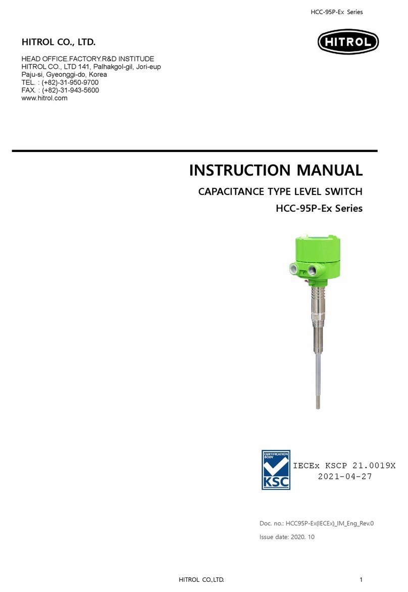
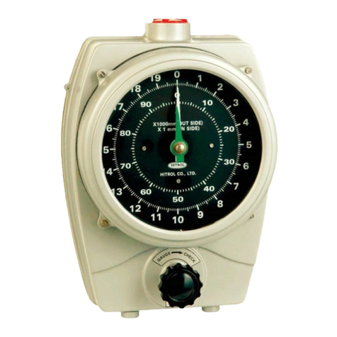
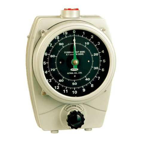
HITROL HRG Series User manual

페이지 1 / 8
Doc. no. : LG-Series_Kor_2022, Rev. 1
Issued date : 2015. 12
HITROL Co., Ltd
HITROL CO., LTD.
HEAD OFFICE.FACTORY.R&D INSTITUDE
HITROL CO.,LTD 141, Palhakgol-gil, Jori-eup
Paju-si, Gyeonggi-do, Korea
TEL. : (00)-82-31-950-9700
FAX. : (00)-82-31-943-5600
www.hitrol.com
INSTRUCTION MANUAL
Liquid Level Gauge
HRG/HTG/HTBG-Series

페이지 2 / 8
Doc. no. : LG-Series_Kor_2022, Rev. 1
Issued date : 2015. 12
HITROL Co., Ltd
Table of Contents
1. Scope ………………………………………………………………………………………………………...... 3
2. Installation …....…………………………………………………………………………………………….. 3
3. Handling ……………………………………………………………………………………………………… 3
3.1 Reflex & Transparent Type
3.2 Two Color Type (Include Duct Mirror)
3.3 Two Color Type (Exclude Duct Mirror)
4. Warming Up Level Gauge For Boiler Service (Tank Service)……………………..... 4
5. Repairment Of Level Gauge ……………………………………………………………………….. 4
6. Leakage Test After Repairment …………………………………………………………………….5
7. Tool For Repairment ……………………………………………………………………………………...5
8. Consumable Part …………………………………………………………………………………….........5
9. Assembling Procedure ……………………………………………………………………………........5
9.1 Reflex Type
9.2 Transparent Type
9.3 Two Color Type
9.4 Tubular Type
10. Drum Level Gauge Muti Pot Type Decomposition and Assembling
Proced ……………………………………………………………………………………………………….......7
Notice
Read this procedure before installation & operating activities on the product.
For personal and system safety, and for optimum installation & operating works
performance, make sure you thoroughly understand the contents before operating & installation
preparations.
All installation & operating protection work, it shall be performed under strict

페이지 3 / 8
Doc. no. : LG-Series_Kor_2022, Rev. 1
Issued date : 2015. 12
HITROL Co., Ltd
1. Scope.
This procedure describes and specifies the general requirements for the installation and application of
protective operating referring to LIQUID LEVEL GAUGE to be fabricated at shop.
2. Installation
2.1 Adjustment of branch nozzle
- If center to center dimension of branch nozzle of Level Gauge for vessel is incorrect, it will cause the
damage of Level Gauge's Glass in particular.
2.2 Installation of drain piping
- Install the drain piping to avoid danger to operating when liquid in Level Gauge is drained out.
3. Handing.
3.1
A. Fully close upper (A), lower valves (B), and drain valve (C)
B. Open drain valve (C).
C. Gradually open upper valve (A) and pour air into Level Gauge.
D. Fully close drain valve (C) and Level Gauge will be pressurized.
E. Gradually open lower valve (B) to indicate level in Level Gauge.
F. Fully open upper (A) and lower valves (B).
Reflex & Transparent Type Two Color Type (Include Mirror) Two Color Type
(Exclude Duct Mirror)
3.2 When some leakage occurs on the Level Gauge, close upper (A) and lower (B) valves and
open drain valve to depressurize the interior of the Level Gauge.
Carry out bolting in accordance with Figure 1.
3.3 When liquid level is not indicated in the Level Gauge.
A. In case of trouble of function of ball check.
Fully close upper (A) and lower (B) valves, then gradually open then slightly.
B. In case upper (A) and lower (B) valves are choked whit something wrong.
Dismantle the Level Gauge and clean it up.

페이지 4 / 8
Doc. no. : LG-Series_Kor_2022, Rev. 1
Issued date : 2015. 12
HITROL Co., Ltd
4. Warming Up Level Gauge For Boiler Service.
4.1 Open drain valve (C), then close lower valve (B), and upper valve (A) a half revolution. Must continue
warming up for about 15 minutes utill temperature of Level Gauge body becomes to 150 ~ 200
Degree Centigrade.
4.2 After warming up, close upper valve(A) and carry out bolting in the sequence shown in the Figure 1.
4.3 Open again upper valve (A) a half revolution, continue warming up for 5 minutes.
4.4 After warming up, close drain valve (C), fully open upper (A) and lower (B) valves.
5. Repairment Of Level Gauge.
5.1 Disassembling
A. Prior to any disassembly of the gauge, first close both upper and lower valves, then open drain valve
to be relieved of all internal pressure.
B. Remove gauge glass carefully from body.
5.2 Clean up
A. The glass, gasket, and cushion should not be re-used, even when the may look perfect. Chipped or
scratched glass should not be used, because such depects become point of high stress concentration.
B. Clean up the metal suface for packing carefully, take off trace of packing and packing paste.
C. Keep the metal surface for packing in perfect condition.
5.3 Reassembling
Refer to the sketch (Item 9.) for assembling procedure.
A. Bolting time
First : A 80 percent of tightening.
Second : A 100 percent of tightening.
B. Bolts & Nuts quantity depends on type and size of the level gauge.
So, actual bolts & nuts quantity may be different from the right Figure 2.
Figure 1.

페이지 5 / 8
Doc. no. : LG-Series_Kor_2022, Rev. 1
Issued date : 2015. 12
HITROL Co., Ltd
6. Leakage Test After Repairment.
Carry out leakage test at the specified pressure.
7. Tool For Repairment.
No. Description Recommended Standard
1
Ratchet Handle
17 mm Box
2
Spanner
17 mm
8. Consumable Part.
No.
Description Sketch No. Description Sketch
1 Reflex Glass 6 Union Gasket
2 Transparent Glass 7 Grand Packing
3 Tube Glass 8 Color Glass
4 Mica Plate 9 Pot Glass Assembly
5 Sealing&Cushion Gasket 10 Lamp
9. Assembling Procedure.
9.1 Install Gasket⑤ Gauge Glass② Cushon④ Gauge cover③ to Gauge Body①.
9.2 Insert Bolt⑥ to center positioned hole of Gauge Cover③ and screw up Washer & Nuts⑦,⑧ softly.
9.3 Insert two Bolt⑥ to adjacent hole and screw up Washer & Nuts⑦,⑧ in softly after adjusting correct
position of Gasket⑤ and Gauge Glass②.
9.4 Insert the rests of Bolts⑥ and Washer & Nuts⑦,⑧.
9.5 Screw up all Washer & Nuts⑦,⑧ in accordance with the sequence for tightening Gauge Cover Bolts
(Figure 1).
No.
Name of Part No.
Name of Part No. Name of Part
1 Gauge Body 4 Cushion 7 Washer
2 Gauge Glass 5 Gasket 8 Nuts
3 Gauge Cover 6 Bolts 9 Mica
Reflex Type Level Gauge.
Model : HRG-1
Model : HRG-1

페이지 6 / 8
Doc. no. : LG-Series_Kor_2022, Rev. 1
Issued date : 2015. 12
HITROL Co., Ltd
Transparent Type Level Gauge.
Model : HTG-1.
Model : HTG-2
Model : HTG-3
9.6 In case of the Tube Glass
9.6.1 Put in into valve body after windin Packing⑤ round the Tube Glass⑥.
9.6.2 Puse Packing⑤ lighty into val body with Gland④.
9.6.3 Tighten the Union Nuts③ to avoid causing leakage.
9.6.4 Bind tight once more Protector② wound by Gland④ with a Hose Band①.
9.7 In case of the PFA Hose
9.7.1 Insert PFA Hose⑥ into Hose Nipple after heating it slightly.
9.7.2 Tighten the Union Nuts③ to avoid causing leakage after pushing Gland lighty into Hose Nipple⑤.
9.7.3 Bind tight once more Protector② wound by Gland④ with a Hose Band①.
No.
Name of Part No.
Name of Part No.
Name of Part
1 Hose Band 3 Union Nut 5 Packing / Hose Nipple
2 Protector 4 Gland 6 Glass / PFA Hose

페이지 7 / 8
Doc. no. : LG-Series_Kor_2022, Rev. 1
Issued date : 2015. 12
HITROL Co., Ltd
Tubular Type Level Gauge
Model : HTBG-1, HTBG-2, HTBG-3
10. Drum Level Gauge Muti Pot Ty
pe decomposition and assembling procedure
10.1 Disassembling Procedure
10.1.1 I remove drain discharges and pressure after having locked upper, lower valve attached to gauge
body as I open up drain valve.
10.1.2 I separate ④Illuminator and duct with ①Gauge body as take to ②Bolt and ③Spring washer.
10.1.3 I take to pieces ⑥Cover, ⑦Gasket, ⑧Packing Strip, ⑨Glass, as take to pieces ⑤Fix Bolts.
10.1.4 I disjoint ⑬Gasket, ⑫Gasket, ⑪Grafoil, ⑩Mica.
10.1.5 You shall disassemble carefully it in case of decomposition so that damage desn't go to part.
10.2 Assembling Procedure
I disassembling reversely of decomposition it after cleaning the face inner Gauge Body.
10.2.1 ⑬Gasket - 3.2T interposition.
10.2.2 ⑫Gasket - o.5T interposition, ⑩Grafoil interposition.
10.2.3 ⑨Mica plate interposition - 2pieces.
10.2.4 It is the insertion to Aluminum Glass Cover.
10.2.5 The Gasket insertion protective Port Glass (0.5T x 16 x 105L)
10.2.6 Port Glass insertion.
I assembling uniformly bolt of four bolt assembly in diagonal line directions and Bolt torque
assembles it to 500 ~ 600 kgf-cm.

페이지 8 / 8
Doc. no. : LG-Series_Kor_2022, Rev. 1
Issued date : 2015. 12
HITROL Co., Ltd
This manual suits for next models
2
Table of contents
Other HITROL Measuring Instrument manuals
