manuals.online logo
Brands
  1. Home
  2. •
  3. Brands
  4. •
  5. HiWeigh
  6. •
  7. Printer
  8. •
  9. HiWeigh NT User manual

HiWeigh NT User manual




1
Warning!
The power supply of NT-T16S printer is only DC 5V/2-3A.
Never use AC mains!
1. INTRODUCTION
NT-T16S is a new type of dot-matrix micro-printer. It is
small (123x165x66cm) in size and light (400g) in weight It is
very attractive in appearance and it has many features.
NT-T16S micro-printer has a serial RS-232C compatible. It
is competent as the output listing devices for many kinds of
intelligent instrument and microcomputer.
1.1 Interface
There is one interface mode in the NT-T16S: SERIAL
interface compatible with RS-232C standard. It is linked
with the master computer through a standard 25pin D type
connector and a cable. The serial connector is female. If the
master computer is furnished with a standard 25pin D type
connector, (IBM PC, or laptop computer etc), it can be linked
with the NT-T16S micro-printer through standard 25 wire
cable and connector. If not, the linkage can be realized
through reformation of the connector on the 25 wire cable.
For details please refer to section “Interface” of NT-T16S.
1.2 Character Codes
NT-T16S provides a font with 448 characters in the internal
ROM. The font includes, English, Greek, German, French,
Russian, Japanese and Chinese characters, a large amount of
math symbols, specific meaning symbols and tabulation
symbols. Characters are 5×7 dot matrix and graphics 6×8.32
special characters can also be defined with the print program.
NT-T16S provides bit image mode. The image mode can be
mixed with characters on the same line.
1.3 Print Commands
NT-T16S provides 35 print commands. Most of these are
compatible with the two most popular standards - IBM and
EPSON. Therefore, NT-T16S can be substituted for 9 pin
printer or even 24 pin printer, usually without modification.
Some new commands are added for special features. The
command for printing curves is an example. This is
convenient for plotting graphs.
1.4 Working Modes
NT-T16S has six working modes - dump, text, bit image,
self-test, on/off line and paper feed mode. The first three
modes are changed by control commands and the last three
are realized by pushing button switches.
1.5 “OFF-Line” Printing
The printing speed of some models, such as NT-T16S, is
slow. For some applications, particularly for industrial
control, a faster printing process is needed .To solve this
problem, a large buffer storage is provided in NT-T16S series.
The master computer transfers data to the buffer very fast.
Then the printer prints “off-line” and the computer can
proceed to other jobs without delay. There are three sizes of
printer buffer : 2K, 8K and 32kbytes. The printer buffer is set
by the manufacturer, and can not be modified by users
themselves.
1.6 Specifications
The general features of the NT-T16S series are listed as
follows:
(1) Interface --Serial
The serial interface is compatible with RS-232C standard.
The baud rate may be selected as 150, 300, 600, 1200, 2400,
4800, 9600 or 19200 bps. The transmission is asynchronous.
The form is handshaking is flag control or x-ON/X-OFF
protocol. The parity check can be selected as Even, Odd or
None by setting an internal dip switch. The signal level is
EIA standard.
(2) Indicators and Switches
There are two LED lamps, Power and SEL indicators. And
two push button switches, SEL select on/off line and LF line
feed switch.
(3) Power Supply - Single DC 5 Volt voltage only. The
current requirement is 2A for NT-T16S.
(4) Ribbon life time is 10,000 lines. (ERC-05)
(5) Printing Paper - plain white paper. The paper width is
44.5 ± 0.5mm. Thickness is 0.07mm. The outer diameter of
paper roll must not be more than 50mm and the paper roll is
placed inside the printer.
2. Installation
2.1 Model Checking
The appearance of the NT-T16S printer is shown as Figure
2-1. Please check the model No. on the label of the printer.
Read all instructions about this model in the manual.
Figure 2-1. Appearance of NT-T16S printer
2.2 Ribbon cassette –Loading
Ribbon cassette has been put inside the printer before
packing. When the printing becomes faint after long use, put
in a new ribbon as follows:
(1) Push forward the removable cover plate with both
thumbs. (Note the arrow on cover plate. See Figure 2-2)
Then take off cover plate carefully.
Figure 2-2. Shows the correct action
(2) Hold the left end of the ribbon cassette with your left
hand. Hold right end in right hand. Right thumb is on top and
forefinger below (Figure 2–4). Lift the right end of the
cassette with the right forefinger. Then lift the left end. The
ribbon cassette will come off easily. Caution –Never lift left
2
end first. This may damage ribbon and printer head.
Figure 2-4. Ribbon Cassette –Unloading
Figure 2-5. Keep right end of cassette up
(3) Take a new ribbon. Hold the cassette as in step 2. Put the
left end on the axle of the gear on the left end of the printer
head. Keep the right end of the cassette up as shown in
Figure 2-5.
Figure 2-6 .Turn the gear as indicated by the arrow
If it is difficult to push the left end down, raise it again. Hold
the cassette with right hand. Press the gear on the cassette
with left thumb. Then rotate slightly as indicated. See arrow
on the cassette cover (Figure 2-6)
Figure 2-7. Press down the right end with thumb.
Secure the cassette on the printer head. The procedure may
be repeated several times until it is easy to push the left end
of the cassette onto the axle of the gear. Then press down the
right end of the cassette with the right thumb as shown in
Figure 2-7.
Figure 2-8. Part of the ribbon rides up over the printer head
Sometimes, the cassette is put in correctly but part of the
ribbon rides up over the printer head as shown in Figure 2-8.
This may be caused by two reasons:
i). The paper has been loaded before the ribbon. Remove
paper and try again.
ii). The ribbon is a used one. Replace with new cassette.
(4) Put on the removable cover plate.
Place the plate on the glide slot. Push into place gently as in
Figure 2-9.
Figure 2-9. Put on cover plate.
2.3 Loading Paper
(1). The removable cover plate must be taken off for loading
paper.
(2). Cut the paper roll as shown in Figure 2-10.
Figure 2-10. Cut the paper roll
The paper roll may be placed inside or outside of the printer
case. When the paper roll is placed inside, the end should be
underneath as Figure 2-11, Caution- Don’t load as in Figure
2-12.
Figure 2-11. Correct paper roll loading End is underneath.
Figure 2-12. Wrong paper roll loading
(3). Switch on 5V/2-3A power supply.
(4). The SEL (Select) button in an ON/OFF toggle. Press
“OFF” the SEL indicator off. Then printer head begins to run.
Feed in paper. The paper enters the printer head and comes
out from the top of the printer head. To stop paper feeding,
press and release LF of SEL button.
(5). Switch off the power supply.
(6). Feed the paper through the slot on the removable cover
plate. Then push the plate back on the printer as before. (See
Section 2.2 Step 4).
2.4 Power Supply
The NT-T16S printer uses a 5V/2-3A DC power supply. A
power supply is specially made for this series and is
recommended. Insert the output plug of the power supply
into the jack (Φ2.5mm) on the back of the printer. When
using other models of power supply, please pay attention to
the voltage and current limits. If the voltage is higher than
DC 5.5V/2-3A or lower than DC 4.5 V, or the maximum
current is less than 2A the printer will not work normally,
and the printer head may be damaged.
Pay attention to the polarity of the power supply. The central
pin of the power jack on the printer is positive. The spring
3
plate in the side of the jack is negative.
Caution: Never connect AC mains directly!
3. Operation
3.1 Serial Interface Connection
The 25 pin connector at the back of the VMP-T series printer
is shown in Figure 3-1.
Figure 3-1. Pin order of the connector of serial interface
The serial interface is standard RS-232C compatible. The pin
signal is shown in Figure 3-2.
Pin
N o
Signal
Source
Description
2
R×D
Printer
Printer receives
data format host
computer
3
T×D
Host
Printer transmits
data when uses the
hand-shaking of
x-ON/ X-OFF.
5
CTS
Printer
Signal set
“MARK” state to
Indicate the printer
is BUSY and can
not accept data,
and “SPACE” state
to indicate the
printer is READY
and can accept
data.
6
DSR
Printer
Signal
set ”SPACE” to
indicate the printer
is ON-LINE
7
GND
Signal ground.
8
DCD
Printer
Same as CTS.
Figure 3-2. The pin signals of serial interface
Signal level is compatible with EIA standard.
The baud rate of serial Interface can be selected as 150, 300,
600, 1200, 2400, 4800, 9600 or 19200bps. To set the baud
rate, take off the re-movable cover and the upper case of the
printer; you will see the DIP switch in the upper right corner
of the PCB. Baud rate can be selected as in Figure 3-3.
Switch near the white mark is K1. The ex-factory baud rate
setting is K1 On, K2 OFF and K3 OFF, which is 9600 bps.
The format of serial interface is asynchronous, shown as in
Figure 3-4.
Start bit (0)
Data bits
Parity bit
Stop bit(1)
1 bit 8 bits 1bit 1bit
Figure 3-4 Asynchronous transmitting format.
START and STOP bits are one bit signals. These signals
come at the beginning and end of a computer message. The
computer message, the DATA, has eight bits, plus a Parity
Check bit. The Parity Check can be set with K5 and K6 DIP
switches as in Figure 3-5. These are set at No Parity
ex-factory, k5 ON, K6 ON.
The signal polarity of serial RS-232C is:
Mark=Logic “1” (EIA low level, -3V to –27V)
Space= Logic “0” (EIA low level, +3V to +27V)
There are two kinds of handshaking to be selected. First is
the flag control. The other is the X-ON/X-OFF protocol. It is
selected with K4 as in Figure 3-6. The K4 is set to ON
ex-factory.
Handshaking select:
Two kinds of handshaking are listed in Figure 3-7
Handshaking
Data
Direction
RS-232C
Interface’s
Signal
Flag Control
Can accept
data
Line 5 &8
are SPACE
state
Can’t accept
data
Line 5 &8
are MARK
state
X-ON/X-DFF
control
Can accept
data
Send X-ON
code (11H)
on line 3
Can’t accept
data
Send X-OFF
code (13H)
on line 3
Figure3-7.Two kinds of handshaking
The operation procedure of serial interface is shown as
follows:
(1) Select baud rate with DIP switches K1- K3.
(2) Select parity with DIP switches K5 and K6.
(3) Select handshaking with DIP switch K4.
(4) When only 32 bytes free space is left in the printer buffer,
signal DCD (line8) and CTS (line 5) are both set to “busy”,
i.e. Mark status, by printer. Otherwise set to “ready”, i.e,
Space status.
(5) Under X-ON/X-OFF control handshaking, the printer
sends X-OFF code (13 in Hex.) when ready. Under Flag
control handshaking, host computer sends data to printer
when both DCD and CTS are ready.
3.2 Indicators and Switches Operation
4
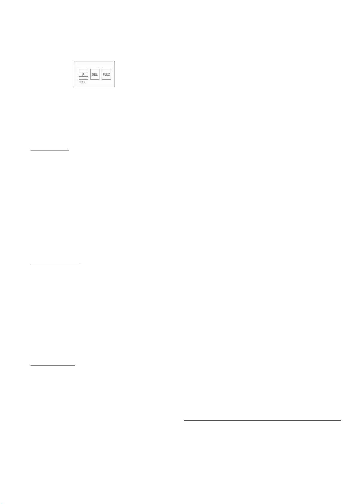
There are two indicators and two button switches on the
panel of the printer. The power indicator is labeled “P”. The
other is the SEL indicator. A button switch is labeled “SEL”
for selecting ON/OFF line. Another is labeled “FEED” for
paper line feeding. (See Figure 3-8.)
Figure 3-8. Indicators and switches
The SEL button can change the SEL indicator’s status. When
the SEL indicator is on, the printer is On- Line.
The printer working mode can be changed with button SEL
and FEED among three modes –self-test, on/off line and
paper feed.
<1>. Self-Test Mode
There are two ways to enter the self-test mode.
(1) Press SEL button when power on the printer. After few
seconds then release, The SEL indicator then turns off and
the printer prints out the self-test sample.
(2) To enter the self-test mode when the printer is on already.
With printer in Off-Line status, press FEED button then press
SEL button. Release both buttons, the printer will enter
self-test mode.
There also are two ways to exit the self-test mode.
(1) The printer will exit self-test mode automatically after
finishing the self-test sample print out.
(2) When the self-test sample is being printed, it can be
terminated by pressing the SEL button. The printer will exit
self-test mode.
<2>. On/ Off Line Mode
After switching on the printer or being in the Self-test mode,
the printer enters On-Line mode. The SEL indicator lights up.
Press the SEL button, SEL indicator lights up. Press the SEL
button, SEL indicator lights off, Printer enters the Off-Line
mode. When printer is in Off-Line mode, it can not receive
data. Press SEL again, Printer re-enters the On-Line mode.
SEL has another function –to interrupt the printout. If SEL is
pressed and then released during a printout, the printer will
stop after completing the current line. At this point you can
load more paper. To complete the printout, press and release
the SEL button again. The printer will run again at the point
printout was interrupted.
<3>. Paper Feed Mode
When print procedure is interrupted, SEL off, the printer
enters Off-Line mode. If paper has to be replaced, press LF
button, then release. Printer will feed paper without printing.
Re-press LF, then release. Printer will stop paper feed.
Printer can also re-enter On-Line mode in the Paper Feed
procedure by pressing the SEL button.
3.3 Self-Test
Self-Test checks condition of printer. If the printer prints out
the Self-Test sample correctly, the printer is working
normally. Other faults will be caused by the interface or
master computer. If there’s a problem with the Self-Test, the
printer or power supply needs repairing.
Self-Test prints out all characters in the fonts. Then print the
messages about interface type and printer head model.
After Self-Test the printer enters On-Line mode. It can then
receive data from the master computer.
3.4 Printer Initialization
Initialization includes default values settings. Default values
are: 3 dot lines spacing, 40 lines form length, 0 values of
vertical tab and horizontal tab, 0 values of right margin and
left margin, normal alphanumeric and graphic character size
(i.e. enlarge factor to receive commands and data)
There are three ways to realize initialization. First is to run
the initialization software on master computer. Master
computer sends initialization commands (ESC@ commands)
to printer.
Second is through self-test procedure.
Third is power on initialization.
3.5 Command Set Selection
There is one command set in NT-T16S: ESC control codes,
other setting –ESC control codes ex-factory.
4. Printing Commands
Summary
NT-T16S provides up to 35 printing commands.
These commands specify the functions of the printer:
(1) Define formatting.
(2) Enlarge or condense characters.
(3) Print image graphics.
(4) Select font.
(5) Define special characters.
(6) Other
Some of these commands are one byte control codes. Some
are ESC code sequences. These sequences start with “ESC”
code, followed by alphanumeric characters.
Printer’s control codes (especially ESC control codes) are
not standardized. Every printer manufacturer has its own
code system. Control codes for the NT-T16S were designed
with reference to the popular IBM and EPSON printers.
Hence, they are compatible with most printers.
5. Operating Note
( 1) Do not dismantle printer head!
( 2) Do not leave power on when not is use for a long period.
( 3)Switch off, if printer does not work normally.
( 4)Power supply must match requirement. See Section 2.5.
( 5) Do not lubricate the printer head.
( 6) Fluff and dust from paper are harmful to printer head.
Check and clear the head when replacing paper roll.
( 7) When replacing ribbon, do not press the cassette too hard.
Otherwise the plastic wheel on the head may be damaged.
( 8) Keep the main circuit board clean.
( 9) Do not remove the IC chips in the main board.
(10) Never use ribbon oil. It may damage printer head.





Other HiWeigh Printer manuals

HiWeigh P902 User manual

HiWeigh

HiWeigh P902 User manual

HiWeigh PT2 User manual

HiWeigh

HiWeigh PT2 User manual

HiWeigh POS58 User manual

HiWeigh

HiWeigh POS58 User manual

Popular Printer manuals by other brands

Dell C2660dn Setup guide

Dell

Dell C2660dn Setup guide

CognitiveTPG ColorPOS A799 Setup guide

CognitiveTPG

CognitiveTPG ColorPOS A799 Setup guide

Oki ES1220n Safety information

Oki

Oki ES1220n Safety information

SEWOO LK-T41 user manual

SEWOO

SEWOO LK-T41 user manual

Oce ColorWave 600 user manual

Oce

Oce ColorWave 600 user manual

Oce TDS400 user manual

Oce

Oce TDS400 user manual

Samsung SL-M2820DW user manual

Samsung

Samsung SL-M2820DW user manual

Astro Machine ASTROJET 2650P quick start guide

Astro Machine

Astro Machine ASTROJET 2650P quick start guide

Roland EGX-600 Service notes

Roland

Roland EGX-600 Service notes

Ricoh Aficio CL4000DN Software guide

Ricoh

Ricoh Aficio CL4000DN Software guide

Canon BJC 6000 - Color Inkjet Printer Service manual

Canon

Canon BJC 6000 - Color Inkjet Printer Service manual

Canon advanced anywhere print user guide

Canon

Canon advanced anywhere print user guide

Epson ET-4810 Series Start here

Epson

Epson ET-4810 Series Start here

Konica Minolta Magicolor 7440 installation guide

Konica Minolta

Konica Minolta Magicolor 7440 installation guide

Digital Equipment DEClaser 2200 installation guide

Digital Equipment

Digital Equipment DEClaser 2200 installation guide

Lexmark Z65n quick start guide

Lexmark

Lexmark Z65n quick start guide

ASTRO ASTROJET IMAGE BLASTER Installation and operating manual

ASTRO

ASTRO ASTROJET IMAGE BLASTER Installation and operating manual

Xerox DocuPrint C621 user guide

Xerox

Xerox DocuPrint C621 user guide

manuals.online logo
manuals.online logoBrands
  • About & Mission
  • Contact us
  • Privacy Policy
  • Terms and Conditions

Copyright 2025 Manuals.Online. All Rights Reserved.