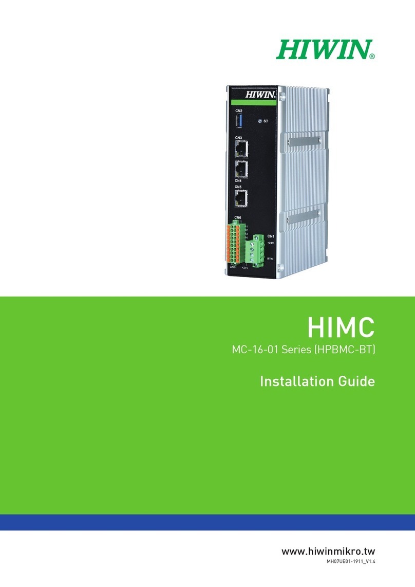
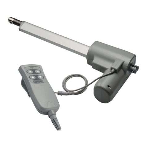
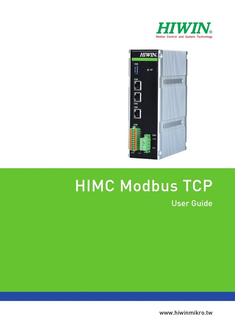
Hiwin LA Series User manual

1
A99UE13-1304
*The contents of this user`s manual are subject to change without notice. If you are
experiencing any technical difculties or do not understand the contents of this manual,
please contact our technical representative or local distributors for assistance.
CONTENTS
Chapter 1 Linear Actuator LA Series User's Guide
1. Product Specication and Operation Environment.............................................. 5
2. Installation Guide......................................................................................... 7
3. Caution Notice............................................................................................ 9
4. Linear Actuator with Quick-Release User's Guide............................................... 10
Chapter 2 LAK Series Controller User's Guide
1. Product Specication and Operation Environment.............................................. 12
2. System Overview......................................................................................... 18
3. Installation Guide......................................................................................... 23
4. Basic Operation Guide.................................................................................. 29
5. Caution Notice............................................................................................ 31
6. LAKC-1 Over Current Protection Box............................................................... 32
Chapter 3 Sealed Lead Acid Batteries User's Guide
1. Battery Specication..................................................................................... 35
2. Battery Power Depletion Chart........................................................................ 35
3. Battery Charging Guide................................................................................. 36
4. Installation of Battery on Controller.................................................................. 36
5. Battery Notice............................................................................................. 38
Chapter 4 LA Series Products Wiring & Installation
1. Linear Actuator Motor Wiring.......................................................................... 39
2. Reed Switch Specication & Application Circuitry............................................... 41
3. PLC Examples............................................................................................ 42
4. Positioning Feedback Device Wiring................................................................ 43
Chapter 5 LAK\LAP Wiring & Installation
1. LAP1/LAP2 Wiring....................................................................................... 54
2. LAP3 Wiring............................................................................................... 56
3. LAP3N Wiring............................................................................................. 58
4. LAP4/LAP4M/LAP4R Wiring.......................................................................... 59
5. LAP4G Wiring............................................................................................. 60
6. LAP4N/LAP4M/LAP4R Wiring........................................................................ 61
7. LAP5 Wiring............................................................................................... 62
8. Connector Drawings..................................................................................... 64
Chapter 6 Appendix
1. Label Description........................................................................................ 66
2. IP rank Description...................................................................................... 67
Chapter 7 Product use in Medical Bed.............................................................................. 68
Important Notes and Operating Safety Regulation:

A99UE13-1304
2
1.Please carefully read this operation manual before using this product. We don't take
responsibility for any damage, accident or injury possibly caused by those who didn't
follow these notes to install.
2.Don't disassemble or reinstall this product yourself. Since this product is designed under
structural operation, computer simulation or physical test, it can't be disassembled or
reinstalled without specialist's permission. If there is any accident or damage caused by
self disassembly or reinstallation, we will not take responsibility.
3.If the appearance is damaged before installing or using, please immediately contact us
or an agent.
4.Ensure to read product label or performance specications indicated by the delivery
document before installing linear actuators.
5.Carefully read power supply indicated on the specication label of a control box
before using this product. Moreover, conrm the supplied power complies with product
requirement. If there is product damage or personnel injury caused by wrong supplied
power, we will not take responsibility.
6.Don't use this product under an environment over the rating load. If there is any damage
or injury, we will not take responsibility.
7. Don't use this product under an impact environment. If there is product damage, accident
or injury, we will not take responsibility.
8.Don't handle this product yourself if faults occur. This product can be repaired by our
qualied technicians only.
9.This appliance is not intended for use by persons (including children) with reduced
physical, sensory or mental capabilities, or lack of experience and knowledge, unless
they have been given supervision or instruction concerning use of the appliance by a
person responsible for their safety.
10. Children should be supervised to ensure that they do not play with the appliance.
Important Notes:
One-year guarantee is provided since the date this product delivered. For product damage
caused by the improper operations (Please refer to notes and installations in this operation
manual.) or natural disasters during this period, we will not take responsibility to replace and
maintain them for free.

3
A99UE13-1304
1.While operating an actuator, don't interrupt the motor operation to avoid failures in
motor or mechanical structure.
2.Please follow the directions and use the nominal voltage of actuator motor with
DC voltage. The supplied DC voltage can provide the maximum current at the
maximum load.
3.If customers use power supplies and controllers themselves, please follow the
current allowed for wire cross-section to install over current protectors (such as
fuse), on the output end of power supplier or the input end of actuator power and
use this over current signal to control actuators, which not only stop movement
or disconnect power supply but also ensure the extension tube of an actuator at
the limit position or under the overload operation can disconnect the power and
provide appropriate control and protection.
4.Unless specially customized, the duty cycle of our actuator should be 10%. The
duty cycle is dened to continuously operate 2 minutes and pause 18 minutes. If
customers operate over duty cycle (10%), please install overheat detection and
prevention devices (as a fan) and use this overheat detection signal to control
actuators to stop movement or disconnect power supply according to control
requirements.
5.If customers don't purchase limit switches, please install the limit switches at the
stroke positions of the extension tube of an actuator yourself and combine that
limiter for power failure on controllers and power suppliers to ensure the power
can be disconnected when the extension tube of an actuator moves to the stroke
and wire position.
6.The actuator is DC driven. When the two input wires of motor power are
exchanged, the extension tube of the actuator will reversely move. Please use
proper controllers and power suppliers while stop. Two input wires of motor power
are short-circuited to provide auxiliary brake. Note that the power of actuator
motor should be disconnected and then short-circuited to avoid short circuit on
power supplier.
7. Don't operate up to the stroke limit if there are no limit switches and controllers
have no overload protection.
8.Don't apply actuators over the maximum load indicated by the specications.
9.If the actuator isn't water-proof, please follow the water-proof regulations.
10.Controller power: AC110V or AC220; the required input power is shown on the
controller's specication tag.
11.Operating temperature: +5°C ~ +40°C (+41°F ~ +104°F).
Operating Safety Regulation:
A99UE13-1304
4
12.Type of protection of applied parts against electric shock is BF.
13.The temperature of Products under storage and transmission is -10℃~+50℃.
14.The clean method of product:Alcohol(70%).
15.The procedure of the broken product:Recycle by local rules.
16.The product should be installed in a safe place where is allowed to take off the
plug easily in an emergency situation.
17.Cycle of inspection (every six months).
18.The hospital bed cleaning procedure must depend on actuator water-proof level
while actuator has assembled with hospital bed.
WARNING:Do not modify this equipment without authorization of the manufacturer.
WARNING:If this equipment is modied, appropriate inspection and testing must be
conducted to ensure continued safe use of the equipment.
WARNING: Read all warnings.
WARNING: Read this manual and follow it carefully before using the device.
WARNING: Remove the power supply cord when the unit is being moved to avoid
damage to the power supply cord.
WARNING: Do not use the unit in the presence of flammable anesthetics or other
flammable substances in combination with air, oxygen-enriched
environment, or nitrous oxide.
WARNING: Keep children away from the device.
WARNING: Before cleaning, turn off the unit and disconnect the power supply cord from
the AC power supply.
WARNING: Always ensure that the supply voltage meets the factory set voltage and
frequency range, as provided on the equipment.

5
A99UE13-1304
TYPE
Max.
Push Force
(N)
Max.
Pull Force
(N)
Max. Current (A)
Max
Holding
Force (N)
Speed (mm/s)
12VDC 24VDC
LAM1-1 4000 3000 12 6 4000 8-11
LAM1-2 2000 2000 12 6 1200 16-21
LAM1-1A 3000 3000 12 6 3000 8-11
LAM2-1 3500 3500 8 4 3000 2-3.5
LAM2-2 2500 2500 8 4 2000 3-6
LAM2-3 1500 1500 6 3 1500 6.5-12
LAM2-4 1200 1200 6 3 800 8-14
LAM3-1 6000 5000 12 6 5000 4-5.5
LAM3-2 4000 4000 10 5 4000 5.5-7.5
LAM3-3 3000 3000 8 4 3000 7-9
LAM3-4 2000 2000 8 4 1500 11.5-14.5
LAI1-1 4000 4000 8 4 1200 6-9
LAI1-1A 4000 4000 10 5 3000 6-9
LAI2-1 12000 10000 3 12000 2-2.5
LAI2-2 8000 8000 4 8000 4-5
LAS1-1 1200 1200 6 2.5 800 8-12
LAS1-2 600 600 6 3 300 16-25
LAS2-1 1800 1200 6 3 1800 4.5-7
LAS2-2 1200 1200 6 4 1000 8-15
LAS3-1 1200 1200 6 2.5 800 8-12
LAS3-2 600 600 6 3 300 16-25
LAS4-1 800 800 5 2.3 600 10-15
LAS4-2 300 300 6 3.6 200 30-46
LAS5-1 800 800 1 600 2.5-4
LAS5-2 300 300 1 200 6-7.5
LAS5A-1 2000 2000 2.3 1500 2.5-4
LAS5A-2 1200 1200 2.3 800 7-8.5
LAN1-1
6000 5000 11
24VDC
24VDC(24Q)
5000
24VDC 12VDC
24VDC(24Q)
5000(12V) 5000(12V) 11 4 6 2.7-5 3-6 5-7
1. Product Specication
1.1 Standard Performance:
Chapter 1 Linear Actuator LA Series User's Guide

A99UE13-1304
6
1.2. Input Voltage: 24VDC or 12 VDC; tolerance ±10%. The rated voltage of actuator is
indicated in the label or enclosed document.
1.3. Rated Duty Cycle: 10%
Denition: 2mis work and 18min pause.
1.4. Protection Class: IP54 (if not specially indicated)
1.5. Operating Temperature: +5℃~ +40℃(+41°F ~ 104°F)
1.6. Atmospheric Pressure 860~1060hpa(12.5~15.4psi).
1.7. Equipment not suitable for use in the presence of a flammable anesthetic mixture
with air or with oxygen or nitrous oxide.
*The specication of LAH1 refers LAN1.
LAN1-2 4000 4000 11 4 6 4000 5-7 4-8 7-9
LAN1-3 3000 3000 10 4 6 3000 5-10 9-11.5
LAN1-4 2000 2000 5.5 2000 12-17
LAN2-1A 6000 6.5 5000 4-6
LAN2-2A 5000 6.5 5000 5-7.5
LAN2-3A 3000 6.5 3000 9-14
LAN3-1 10000 6000 24VDC 24VDC(24Q) 10000 24VDC 24VDC(24Q)
8.3 12 4.5-8 7-11
LAN3-2 7000 6000 8 11 7000 6.5-9 9-13
LAN3-3 5000 5000 7 11 5000 9-12.5 13-18
LAN3A-1 12000 6000 8.3 12 12000 3-5 4.5-7
LAN3A-2 10000 6000 8.3 12 10000 4.5-8 7-11
LAN3A-3 7000 6000 8 12 7000 7-9 9-13
LAN3A-4 5000 5000 7 12 5000 9.5-12.5 13-18
LAN4-1 3500 3500 12 6 3500 3.5-7
LAN4-2 3000 3000 12 6 3000 4.2-9
LAN4-3 2000 2000 12 5 2000 6-13
LAN4-4 1500 1500 12 5 1500 8.5-20
LAN5-1 8000 4000 24VDC 24VDC(24Q) 6000 24VDC 24VDC(24Q)
7000(24Q) 5 8 2-3.5 5-7
LAN5-2 6000 4000 4.5 8 5000 3-4.5 7-9
LAN5-3 4000 3000 4 6 4000 4-5.5 9-11
LAN5-4 3000 2000 4 6 1500 6-9 14-19
LAC1 2000 500 5 8 2000 8-12 13-16
LAC3 2000 500 5 2000 8-12

7
A99UE13-1304
2.1.1 The term "lowest position" in this user's guide refers to the position such that
there is no further movement towards the DC motor while the actuator is
powered on. (Please refer to the gure below.)
Motor
End Joint
Extrusion Tube
Front Joint
(Lowest Position)
Extrusion Tube
End Joint Lower limit switch Upper limit switch Front Joint
2.1. Please ensure that the extension tube is in the "lowest position" before installing
actuators.
2.1.2 External limit switch: For installing an external limit switch, please ensure the
extension tube is in the lowest position before installing an actuator (Please
refer to the gure below.).
※If an actuator doesn't have an external limit switch installed, you must install the
stroke limiter on an actuator yourself. The distance between two actuator limit
switches can't be longer than the stroke of the actuator. And then rotate the
extension tube to adjust the length of an actuator, which can meet the minimum
requirements to install actuators.
※To avoid any wrong movements of actuators, there shouldn't have any magnetic
materials close to external limit switches within 30mm.
2. Installation Guide

A99UE13-1304
8
2.2.The front and end joints of the linear actuator should be mounted onto two xed
positions on the main chassis. Locations of these xed positions should be chosen
according to the stroke length of the linear actuator (Users must be cautious that the
two-way movement of linear actuator must be smooth and within the stroke length
after installed onto the xed positions). Please ensure that no obstacle exists along
the travel path of the actuator.
2.3.After the xed positions have been selected, install the xtures onto these selected
positions of the main chassis. These xtures are used to x the front and end joints
of linear actuator to the chassis.
2.4.Assemble the front and end joints of the linear actuator onto the two xtures using
xture bolts. Please ensure that the xture bolts are able to rotate freely after this
step is completed. On the other hand, users should also make sure that the xture
bolts would not drop off either during operating or resting period.
2.5.The chassis of linear actuator should be xed in the horizontal direction if it is going
to be operated in this direction and likewise for vertical operation.
2.6.The operation of the linear actuator should be tested manually after the installation
is completed. Users should make sure that:
•The travel distance of the actuator is matching the requirement of the structural
design.
2.1.3 LAC1 Installation LAC3 Installation
Installing Hole 4 - M8
Travel Direction
Motor
Fixing Hold 6-M6

9
A99UE13-1304
•The upper and lower limit switches are operated normally.
•The motor stops when the extension tube reaches upper and lower limit switch
positions.
If the linear actuator fails to meet any of these conditions, please repeat steps 2.2
to 2.4 until the above mentioned clauses are met
2.7. The entire installation is nished only if steps 2.1 to 2.6 are executed successfully.
2.8. HIWIN Mikrosystem Corp. cannot take any responsibility for any injuries and/or
damages caused as a result of not complying with the clauses of this section.
3.1. Don't use this product to make current transient inversion. If you try to backwardly
move the present extension tube that forwardly moves, you must stop the motor and
apply the reverse current to make backward movement. On the contrary, if you want
the extension tube backward moved to forward, the way to supply current will be the
same as mentioned above.
3.2. Don't use this product with a radial load (Please refer to gures and tables below.)
because an actuator more appropriately applies to take the axial load. If there is
product damage, accident or personal injury caused by improper load, we will not
take any legal responsibility.
3.2.1 LA Series
3. Note:
Load Load
Actuator
Axial Direction

A99UE13-1304
10
3.3. For xing the extension tube in this actuator on one guding mechanism, please
refer to the installation guide. If it is not xed on any mechanism, it could idle.
3.2.2 LAC1 Series
LAC3 Series
4.1 LAN1、LAN2 Series:
4.1.1 Be sure the moving ambits of handle will not interfere with other mechanisms
when assembling.
4.2.1 To avoid mistake touching, please put up warning notice on the mechanisms.
4.3.1 There must have load on the actuator to active quick-release.
4.4.1 The way to active quick-release is rotating the handle as the following drawing.
4.5.1 When the speed of quick-release is too fast, please free or reverse the handle
immediately.
4.6.1 The quick-release function for LAN1 and LAN2 series can only be used in
vertical pushing force condition, it may inactive in pulling force or slopping
force.
4. Linear Actuator with Quick-Release User’s Guide

11
A99UE13-1304
5.1.To avoid mistake touching, please put up warning notice on the mechanisms or
lifters.
5.2.The way to active quick-release is pulling the handle as the following drawing.
5.3.When the speed of quick-release is too fast, please adjust the handle extending
length immediately; The screw beside the handle can adjust and limit the max.
extending length of the handle.
5.4.The quick-release function for LAN3 series can only be used in vertical pushing
force condition, it may inactive in pulling force or slopping force.
5. LAN3 Series:
Load Load
slow
quick
Load

A99UE13-1304
12
1.Product Specication and Operation Environment
1. LAK2LR Series:
1.1 LAK2LR can combine uniaxial linear actuator with external limit switch.
1.2 The output power of a controller is 108VA (The output voltage is 24VDC.).
1.3 Fuse specication:2A/20mm(220/230VAC),
3A/20mm(100/110VAC).
Chapter 2 LAK Series Controller User's Guide
6.1.Be sure the release cable is normal extended without any crooked when assembling,
and the end of wire is certainty xed on the mechanisms or hospital beds.
6.2.To avoid mistake touching, please put up warning notice on the mechanism or
facilities.
6.3.The way to active quick-release is pulling the handle and let the wire extend as the
following drawing.
6.4.Please lift the load temporary before active quick-release function, thus can pull the
wire out and separate the clutch mechanism.
6.5.Be sure to keep the clutch separated and restore the load on actuator, and the load
can extend and retract along axis direction.
6.6.The load on actuator cannot be the operating staff himself.
6.7.Be sure the release handle and clutch mechanism are restored by extending or
retracting the actuator after quick-release function is actived.
6. LAN5 Series:
Load

13
A99UE13-1304
3. LAK2 Series(UL):
3.1 LAK2 can combine uniaxial or bi-axial linear actuators. For the sake of safety, two
actuators can't be operated simultaneously. Don't press the “△” key and “▽”
key at the same time.
3.2 The output power of a controller is Max.144VA.
3.3 The input power is 100~240VAC.
3.4 Over current A:2.5A, B:3A, C:4A, D:5A, E:6A
3.5 Recommended installation method:
4. LAK2B Series
4.1 LAK2B can combine uniaxial or bi-axial linear actuators.
4.2 The output power of a LAK2B controller is 144VA (The output voltage is 24VDC.).
4.3 1.3Ah or 2.9Ah lead acid batteries can be selected, built-in auto charge circuit
without an external charger.
4.4 Fuse specication:2A/20mm(220/230VAC),
3A/20mm(100/110VAC),
10A/20mm(Battery).
4.5 Note: Please charge battery for at least 8 hours before initial use.
5. LAK2B Series (UL):
5.1 LAK2B can combine uniaxial linear actuators.
5.2 The output power of a LAK2B controller is 72.5VA (The output voltage is 24VDC).
5.3 1.3Ah or 2.9Ah lead acid batteries can be selected, built-in auto charge circuit
without an external charger.
2. LAK2 Series:
2.1 LAK2 can combine uniaxial or bi-axial linear actuators. For the sake of safety, two
actuators can't be operated simultaneously. Don't press the “△” key and “▽”
key at the same time.
2.2 The output power of a controller is 108VA (The output voltage is 24VDC.).
2.3 LAK2 can be driven by DC (12VDC / 24VDC), which the output power depends on
the maximum power of power supply.
2.4 Fuse specication:2A/20mm(220/230VAC),
3A/20mm(100/110VAC),
15A/20mm(12VAC).

A99UE13-1304
14
7. LAK2D Series:
7.1 LAK2D can combine uniaxial or bi-axial linear actuators. For the sake of safety, two
actuators can’t be operated simultaneously. Don’t press the “△” key and “▽”
key at the same time.
7.2 The output power of a controller is 108VA (The output voltage is 24VDC.).
7.3 LAK2D is equipped with auto protector to avoid over current caused by overload or
other abnormal situations; two 9V alkaline batteries can be added during temporary
interruption to reduce the load.
7.4 LAK2D has no charge function, the battery can only afford the load to be declined
urgently under a powerless state.
7.5 LAK2D can combine LAM3 to save the space and be easily installed (Please refer
to the gure below.).
7.6 Fuse specication:2A/20mm(220/230VAC),
3A/20mm(100/110VAC).
6. LAK2BN Series:
6.1 LAK2B can combine uniaxial or bi-axial linear actuators, and provide an intelligent
controller as well as application software according to customer requirements.
6.2 The output power of a LAK2B controller is 144VA (The output voltage is 24VDC.).
6.3 1.3Ah or 2.9Ah lead acid batteries can be selected, built-in auto charge circuit
without an external charger.
6.4 Fuse specication:2A/20mm(220/230VAC),
3A/20mm(100/110VAC),
10A/20mm(Battery).
6.5 Note: Please charge battery for at least 8 hours before initial use.
5.4 LAK2B input voltage is 120VAC。
5.5 Fuse specication:3A/20mm,
10A/20mm(Battery).
5.6 Note: Please charge battery for at least 8 hours before initial use.

15
A99UE13-1304
8. LAK2J Series(UL approved only DC IN versions):
8.1 LAK2J can combine uniaxial or bi-axial linear actuators.
8.2 A portable controller is designed in this product driven by two 12VDC lead acid
batteries with 4.5Ah without built-in transformer.
8.3 The EMERGENCY button on a panel can disconnect the function of a controller to
protect customers users.
8.4 Users can directly press the UP on DOWN key on a panel without a key box (The
button can only be use to do the up and down control for the rst axis).
8.5 Over current protection and slow start are provided to avoid misuse.
8.6 A LAKCH-A or LAKCH-B charger is required for charging, but AC-IN type are
charged by connecting to 110V or 220V directly.(For the sake of safety, a controller
can’t be used in charging.).
8.7 In 30 seconds after stopping operation, it will automatically become energy-saving
mode to increase the use time. The low-level buzz and LED power indication are
provided as well.(In AC-IN type, the LED on the control panel are need to feed 110V
or 2200V ).
8.8 Fuse specication:15A/20mm.
8.9 Note: Please charge battery for at least 12 hours before initial use.
9. LAK4 Series:
9.1 LAK4 can combine uniaxial to 3-axial linear actuators.
9.2 The output power of a controller is 72.5VA (The output voltage is 24VDC.).
9.3 LAK4 can combine LAN1 to save the space and be easily installed (Please refer to
the gure below.).
9.4 Fuse specication:2A/20mm(220/230VAC),
3A/20mm(100/110VAC).

A99UE13-1304
16
11. LAK4N Series:
11.1 Combine uniaxial to 6-axial linear actuators.
11.2 The output power of a controller is 216VA (The output voltage is 24VDC.).
11.3 A bolt is provided to avoid actuators and pluggable AC power cord accidentally
being removed as well as reduce the danger when using.
11.4 1.3Ah or 2.9Ah lead acid batteries for LAK2B can be selected, built-in auto charge
circuit without an external charger.
10. LAK4D Series (UL):
10.1 LAK4D can combine uniaxial to 4-axial linear actuator.
10.2 The output power of a controller is 72.5VA (The output voltage is 24VDC).
10.3 A bolt is provided to avoid actuators cord and pluggable AC power cord from
accidentally being removed as well as reduce the danger when using.
10.4 LAK4D can combine with HIWIN linear actuator LAN5, and has an anti-loose
function to prevent an actuator from being removed; it is saving space and easy to
install. (Please refer to the gure below)
10.5 LED power display.
10.6 Fuse specication:2A/20mm(220/230VAC),
3A/20mm(100/110VAC).
10.7 The protective rank of anti-shock of this product is BF.
10.8 The sign on the case of this product indicates that here is a function for
“Functional Ground”.(For the moment,we don’t provide the function).

17
A99UE13-1304
12. LAK6B Series:
12.1 Combine uniaxial to 6-axial actuators, and provide an intelligent controller as well
as application software according to customer requirements.
12.2 The output power of a controller is 216VA (The output voltage is 24VDC.).
12.3 1.3Ah lead acid batteries can be selected, built-in auto charge circuit without an
external charger.
12.4 Over current protection and slow start.
12.5 Energy-saving device and replaceable fuse with spare one on a socket.
12.6 External grounding and LED power indication.
12.7 Fuse specication:4A/20mm(100/110/220/230VAC).
11.5 Externally connect the power supply to provide higher driving power.
11.6 Over current protection and slow start are provided to avoid customer misuse.
11.7 LAK4N can combine LAN1 to save the space and easily install (Please refer to the
gure below.).
11.8 Fuse specication:4A/20mm(100/110/220/230VAC),
15A/20mm(Battery).
11.9 Note: Please charge battery for at least 8 hours before initial use.

A99UE13-1304
18
1. LAK2LR Series:
Taking LAM for example
2. LAK2 Series:
Taking LAN2 for example
2. System Overview
Control Box
Motor Cord
External Limit Wire
Power Card
Key Box
Power
LAP2-1

19
A99UE13-1304
3. LAK2B/LAK2BN Series:
Taking LAN1/LAC3 for example
4. LAK2D Series:
Taking LAM3 and LAN1 for example

A99UE13-1304
20
5. LAK2J (DC-IN)Series:
Taking LAN3 for example
6. LAK2J (AC-IN)Series:
Taking LAN3 for example
Other manuals for LA Series
1
This manual suits for next models
51
Table of contents
Other Hiwin Controllers manuals