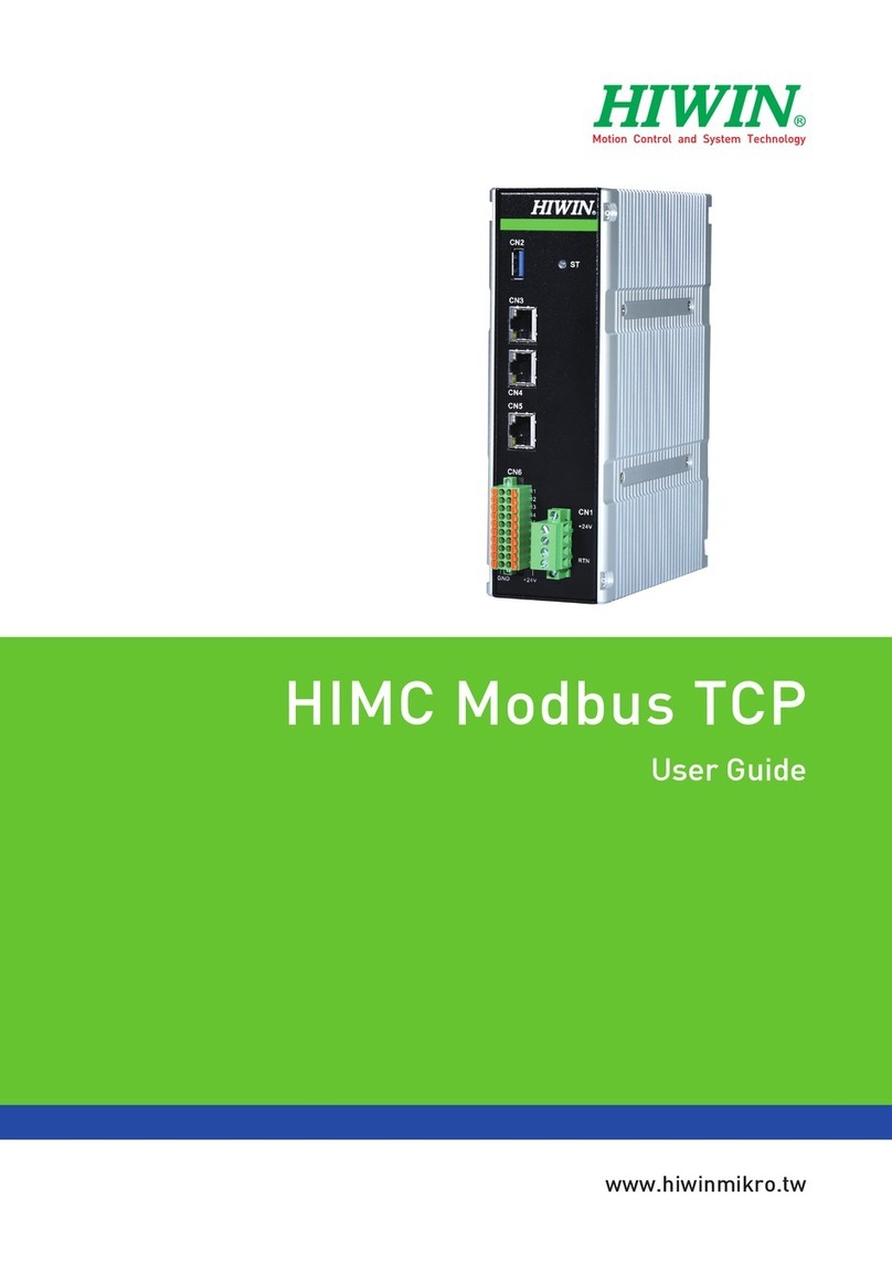
Hiwin HIMC User manual

www.hiwinmikro.tw
MC-16-01 Series (HPBMC-BT)
Installation Guide
HIMC
MH07UE01-1911_V1.4

HIMC Installation Guide Revision History
Revision History
The version of the guide is also indicated on the bottom of the front cover.
Release Date Version Applicable Product Revision Contents
Nov. 29th, 2019 1.4 HIMC Modify the description of CN3 and CN4 in Table 3.1.1.
Mar. 22th, 2019 1.3 HIMC 1. Modify names of digital I/O.
2. Modify chapter’s arrangement.
Dec. 5th, 2017 1.2 HIMC Fix typo in section “LED Indicator”.
Oct. 16th, 2017 1.1 HIMC Fix section number in Chapter 3.
Sep. 1st, 2017 1.0 HIMC
1. Reformat section “Safety Instructions Before
Use.”
2. Add wiring conductor limit temperature.
Aug. 24th, 2017 0.9 HIMC
1. Modify input power rating.
2. Modify CN1 wiring requirement.
3. Remove sourcing input option (NPN).
4. Modify built-in I/O current limit and wiring
diagrams.
5. Modify storage temperature.
Aug. 22th, 2017 0.8 HIMC Change model name.
Aug. 21st, 2017 0.7 HIMC 1. Add description for connector installation.
2. Add description for mounting orientations.
Aug. 16th, 2017 0.6 HIMC Reformat contents.
Aug. 8th, 2017 0.5 HIMC
1. Modify chapter’s arrangement.
2. Modify description of LED indicator.
3. Modify the maximum number of axes in
specifications.
May 17th, 2017 0.4 HIMC Modify Ethernet port speed.
May 12th, 2017 0.3 HIMC 1. Add Chapter 1 “Introduction”.
2. Add Chapter 4 “Troubleshooting”.
Release Date
MH07UE01-1911_V1.4
Version

HIMC Installation Guide Revision History
HIWIN MIKROSYSTEM Corp. 3
May 5th, 2017 0.2 HIMC 1. Add figures in all sections.
2. Add Chapter 3 “Connectors and Wiring”.
Apr. 24th, 2017 0.1 HIMC First edition.

HIMC Installation Guide Table of Contents
Table of Contents
1. About this Guide............................................................................................................................................... 1-1
1.1 General precautions............................................................................................................................ 1-2
1.2 Safety precautions .............................................................................................................................. 1-3
1.3 Package list......................................................................................................................................... 1-6
2. Specifications ................................................................................................................................................... 2-1
2.1 HIMC specifications ............................................................................................................................ 2-2
2.2 Dimensions ......................................................................................................................................... 2-4
2.3 Installation ........................................................................................................................................... 2-5
2.4 LED indicator....................................................................................................................................... 2-6
3. Wiring ............................................................................................................................................................... 3-1
3.1 Overview ............................................................................................................................................. 3-2
3.2 CN1 power input ................................................................................................................................. 3-3
3.3 CN6 digital I/O..................................................................................................................................... 3-4

HIWIN MIKROSYSTEM CORP. 1-1
1. About this Guide
1. About this Guide............................................................................................................................................... 1-1
1.1 General precautions............................................................................................................................ 1-2
1.2 Safety precautions .............................................................................................................................. 1-3
1.3 Package list......................................................................................................................................... 1-6

HIMC Installation Guide About this Guide
1-2 HIWIN MIKROSYSTEM CORP.
MH07UE01-1911
1.1 General precautions
This guide is for HIMC, HIWIN Motion Controller. Before using the product, please carefully read through
this guide. HIWIN Mikrosystem (HIWIN) is not responsible for any damage, accident or injury caused by
failure in following the installation instructions and operating instructions stated in this guide.
Do not disassemble or modify the product. The design of the product has been verified by structural
calculation, computer simulation and actual testing. HIWIN is not responsible for any damage,
accident or injury caused by disassembly or modification done by users.
Before installing or using the product, ensure there is no damage on its appearance. If any damage
is found after inspection, please contact HIWIN or local distributors.
Carefully read through the specification noted on product label or technical document. Install the
product according to its specification and installation instructions stated in this guide.
Ensure the product is used with power supply specified on product label or in product requirement.
HIWIN is not responsible for any damage, accident or injury caused by incorrect power supply.
Do not repair the product by yourself when it malfunctions. The product can only be repaired by
qualified technician from HIWIN.

HIMC Installation Guide About this Guide
HIWIN MIKROSYSTEM CORP. 1-3
MH07UE01-1911
1.2 Safety precautions
Carefully read through this guide before installation, transportation, maintenance and examination.
Ensure the product is correctly used.
Carefully read through electromagnetic (EM) information, safety information and related precautions
before usage.
Safety precautions in this guide are classified into “Warning”, “Attention”, “Prohibited” and “Required”.
Signal Word Description
It indicates if the precaution is not observed, it is likely to cause property
loss, serious injury or death.
It indicates the precaution must be observed.
It indicates prohibited activity.
It indicates mandatory activity.
If the product is not used in the manner specified in this guide, the protection provided by the
product may be impaired.

HIMC Installation Guide About this Guide
1-4 HIWIN MIKROSYSTEM CORP.
MH07UE01-1911
Operation
Do not touch the terminals and the internal part of the product when power
on, or it may cause electric shock.
Do not touch the terminals and internal part of the product within 10 minutes
after power off, or the residual voltage may cause electric shock.
Do not modify wiring when power on, or it may cause electric shock.
Do not damage, apply excessive force to, place any heavy object on the cable
or put the cable between two objects, or it may cause electric shock or fire.
Do not use the product in location which is subject to humidity, corrosive
materials, flammable gas or flammable materials.
Storage
Do not store the product in location which is subject to water, water drop,
direct sunlight, harmful gas or liquid.
Transportation
Carefully move the product to avoid damage.
Do not apply excessive force to the product.
Do not stack the products to avoid collapse.
Installation site
Do not install the product in location with high ambient temperature and high
humidity or location which is subject to dust, iron powder or cutting powder.
Install the product in location with ambient temperature stated in the manual.
Use cooling fan if the ambient temperature is too high.
Do not install the product in location which is subject to direct sunlight.
The product is not drip-proof or waterproof, so do not install or operate the
product outdoor or in location which is subject to water or liquid.
Install the product in location with less vibration.

HIMC Installation Guide About this Guide
HIWIN MIKROSYSTEM CORP. 1-5
MH07UE01-1911
Installation
Do not place heavy object on the product, or it may cause injury.
Prevent any foreign matter from entering the product, or it may cause fire.
Install the product in the specified orientation, or it may cause fire.
Avoid strong shock to the product, or it may cause malfunction or injury.
When installing the product, take the product weight into consideration.
Improper installation may cause damage.
Install the product on noncombustible objects, such as metal to avoid fire.
Wiring
Ensure wiring is correctly performed, or it may cause malfunction or burn.
There is a risk of injury or fire.
Operation and transportation
Use power supply specified in product specification, or it may cause injury or
fire.
The product may
suddenly start to operate after power supply recovers.
Please do not get too close to the product.
Maintenance
Do not disassemble or modify the product.
Do not repair the product by yourself when it malfunctions, please contact
HIWIN for help.
The product is for indoor use. It can only be kept in the environment that the
degree of contamination is 2. Clean up the appearance with a dry cloth.

HIMC Installation Guide About this Guide
1-6 HIWIN MIKROSYSTEM CORP.
MH07UE01-1911
1.3 Package list
The product package comes with the following items. If any of them is missing or damaged, please contact
Customer Service Department for assistance.
1 x HIWIN Motion Controller, HIMC
1 x DIN Mount Kit
1 x Phoenix Contact 20 pin
1 x Phoenix Contact 4 pin

HIWIN MIKROSYSTEM CORP. 2-1
2. Specifications
2. Specifications ................................................................................................................................................... 2-1
2.1 HIMC specifications ............................................................................................................................ 2-2
2.2 Dimensions ......................................................................................................................................... 2-4
2.3 Installation ........................................................................................................................................... 2-5
2.4 LED indicator....................................................................................................................................... 2-6

HIMC Installation Guide Specifications
2-2 HIWIN MIKROSYSTEM CORP.
MH07UE01-1911
2.1 HIMC specifications
Motion control
Maximum slaves Up to 16 slaves. (including motor drives and I/O modules)
Motion types Single axis motion: point-to-point, jog
Group interpolation: multi-axis linear interpolation
Motion profile Trapezoidal profile with smooth factor from 0 to 500 msec
Dynamic error compensation Geometric compensation for increasing positioning accuracy
Position precision 32-bit resolution
Numerical precision Double floating-point precision real-time trajectory generation
Programming
Motion script
HMPL (HIWIN Motion Programming Language)
High-level multi-tasking environment
Up to 11 simultaneously running user tasks
User-defined variable table Up to 512,000 double precision user defined variables
User program size Up to 10MB of source code
Software Library library for C / C++ / C#... etc.
Communication
Ethernet port 10/100/1000 Base-T Ethernet with TCP/IP x2
USB USB 3.0 x1
mega-ulink over EtherCAT
Cycle time 250µs for up to 16 slaves
Supported modules All HIWIN mega-ulink over EtherCAT compatible motor drives (D1, D2T,
D1-N, E1) and HIOM I/O module
Computational capability
Processor Intel® Celeron® Bay Trial J1900 (Quad-core)
Memory On board 2GB DDR3L 1333 MHz SDRAM
Storage mSATA SSD 32G

HIMC Installation Guide Specifications
HIWIN MIKROSYSTEM CORP. 2-3
MH07UE01-1911
Built-in I/O
General Purpose Input 8x Opto-isolated 24V, delay time within 1ms. (Sinking, PNP)
General Purpose Output 8x Opto-isolated 24V, delay time within 1ms.
GPIO current limit Max. 100mA. Total 0.8A per bank of 8.
Power
Main power Input DC 24V / 0.6A
Power consumption Max. 14.4W
Status LED Refer to Section 2.4
Mechanical characteristics
Size (WxHxD) 57 x 180 x 140 mm.
Weight approx.1200g
Mounting DIN in an enclosure or industrial panel
Chassis construction Extruded aluminum alloy for fan-less support
Environment
Protection class IP30
Operating temp. 0°C~50°C
Storage temperature -20°C~85°C
Operating altitude Up to 2000m.
Ventilation fan-less convection cooling
Humidity 5%~95%, non-condensing
Vibration Random: 5~500Hz, 2G
Sine: 10~500Hz, 5G
Shock 5G duration: 11ms
Certificates
EMC EN61000-6-2, EN61000-6-4
Safety UL61010-1, UL61010-2-201,
EN61010-1, EN61010-2-201, ISO 14971

HIMC Installation Guide Specifications
2-4 HIWIN MIKROSYSTEM CORP.
MH07UE01-1911
2.2 Dimensions
Figure 2.2.1 Dimensions (unit: mm)

HIMC Installation Guide Specifications
HIWIN MIKROSYSTEM CORP. 2-5
MH07UE01-1911
2.3 Installation
REQUIRED
Based on UL61010-2-201, HIMC should be mounted on the industrial control panel and the maximum
ambient temperature is 50°C.
Step 1. Align the mounting holes of the bracket in the system and those on the DIN rail bracket.
Step 2. Use the provided mounting screws to secure the bracket in place.
Step 3. Mount the product on the industrial control panel with the recommended orientation, as Figure
2.3.2 shows.
Figure 2.3.1 DIN rail bracket

HIMC Installation Guide Specifications
2-6 HIWIN MIKROSYSTEM CORP.
MH07UE01-1911
Figure 2.3.2 Recommended mounting orientation
2.4 LED indicator
Table 2.4.1 LED indicator
Color Status Description
No light Power off
White Solid Boot
Blinking Initializing
Green Solid Operation
Blinking Pre-operation
Red Solid Hardware binding failed
Blinking Error
Control Panel
Upright
Direction
Upright
Direction
DIN rail

HIWIN MIKROSYSTEM CORP. 3-1
3. Wiring
3. Wiring ............................................................................................................................................................... 3-1
3.1 Overview ............................................................................................................................................. 3-2
3.2 CN1 power input ................................................................................................................................. 3-3
3.3 CN6 digital I/O..................................................................................................................................... 3-4

HIMC Installation Guide Wiring
3-2 HIWIN MIKROSYSTEM CORP.
MH07UE01-1911
3.1 Overview
Figure 3.1.1 HIMC front panel
Table 3.1.1 Wiring overview
Item Connector Description
CN1 Phoenix 4 pin Power Input 24V
CN2 USB connector Update controller firmware
CN3 RJ45 Communication with customers’ PC or devices
(Default IP address: 0.0.0.0)
CN4 RJ45 Communication with customers’ PC or devices
(Fixed IP address: 169.254.188.20)
CN5 RJ45 Communication with mega-ulink over EtherCAT (MoE) slaves
CN6 Phoenix 20 pin Digital inputs/outputs
ST N/A Controller status

HIMC Installation Guide Wiring
HIWIN MIKROSYSTEM CORP. 3-3
MH07UE01-1911
3.2 CN1 power input
REQUIRED
Use SELV or double insulated qualified power supply based on UL60950, UL61010-1 or UL61010-2-201
standard.
The power input connector (CN1) is suitable for AWG (American Wire Gauge) 18~22 (0.326~0.823 mm2).
With the rated load current, conductor limit temperature should be less than 60°C for operation.
Screw torque: 0.5N-m
Note: Make sure that the voltage of the DC power source is stable before connecting HIMC to DC power
input.
Figure 3.2.1 CN1 connector type
Table 3.2.1 CN1 pin assignment
Pin Name Description Remarks
1 +24V +24VDC supply
Power requirement: DC 24V/0.6A
2 N/C Not connected
3 N/C Not connected
4 RTN +24VDC supply return

HIMC Installation Guide Wiring
3-4 HIWIN MIKROSYSTEM CORP.
MH07UE01-1911
3.3 CN6 digital I/O
REQUIRED
Use SELV or double insulated qualified power supply based on UL60950, UL61010-1 or UL61010-2-201
standard.
The digital I/O connector (CN6) is suitable for AWG (American Wire Gauge) 18~24 (0.205~0.823 mm2). With
the rated load current, conductor limit temperature should be less than 60°C for operation.
Screw torque: 0.5N-m
HIMC provides 8 general purpose inputs and 8 general purpose outputs. The input type can be sinking
input logic or PNP type.
Figure 3.3.1 CN6 connector type
Table 3.3.1 CN6 pin assignment
Pin Name Description Pin Name Description
1 I1 Digital input 1 11 O1 Digital output 1
2 I2 Digital input 2 12 O2 Digital output 2
3 I3 Digital input 3 13 O3 Digital output 3
4 I4 Digital input 4 14 O4 Digital output 4
5 I5 Digital input 5 15 O5 Digital output 5
6 I6 Digital input 6 16 O6 Digital output 6
7 I7 Digital input 7 17 O7 Digital output 7
8 I8 EMO 18 O8 Digital output 8
9 N/C Not connected 19 OCOM Output common point
10 VIN +24VDC supply 20 GND Digital Ground
Note: The last input (I8) is for Emergency Machine Off.
This manual suits for next models
3
Table of contents
Other Hiwin Controllers manuals
Popular Controllers manuals by other brands

thomann
thomann the t.racks DSP 4x4 Mini Amp manual

Honeywell
Honeywell Touchpoint Plus Technical handbook

Honeywell
Honeywell CIPer 50 user guide

Johnson Controls
Johnson Controls FMS-2000C installation guide

Invertek Drives
Invertek Drives OPTIDRIVE E3 Series quick start guide

Texas Instruments
Texas Instruments TMS320C6000 DSP reference guide

Mitsubishi
Mitsubishi Q64AD installation manual

Multiplex
Multiplex ROXXY MSB 45A operating instructions

Simply Automated
Simply Automated DKIT-02 Getting started

Velleman
Velleman TRCV3 manual

DTM System
DTM System miniR2 Series Assembly and operating manual

Danfoss
Danfoss vlt soft starter mcd 500 Service manual