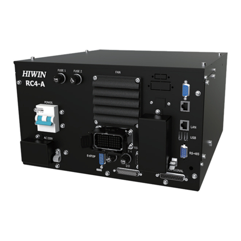
Hiwin RC4 User manual

www.hiwin.tw
User Manual
Robot Controller
RC4
Original Instruction

INDUSTRIE 4.0 Best Partner
Multi-Axis Robot
Pick-and-Place / Assembly /
Array and Packaging / Semiconductor /
Electro-Optical Industry /
Automotive Industry / Food Industry
• Articulated Robot
• Delta Robot
• SCARA Robot
• Wafer Robot
• Electric Gripper
• Integrated Electric Gripper
• Rotary Joint
Single-Axis Robot
Precision / Semiconductor /
Medical / FPD
• KK, SK
• KS, KA
• KU, KE, KC
Torque Motor
Rotary Table
Aerospace / Medical / Automotive Industry /
Machine Tools / Machinery Industry
• RAB Series
• RAS Series
• RCV Series
• RCH Series
Ballscrew
Precision Ground / Rolled
• Super S Series
• Super T Series
• Mini Roller
• Ecological & Economical
Lubrication Module E2
• Rotating Nut (R1)
• Energy-Saving & Thermal-
Controlling (Cool Type)
• Heavy Load Series (RD)
• Ball Spline
Linear Guideway
Automation / Semiconductor / Medical
• Ball Type--HG, EG, WE, MG, CG
• Quiet Type--QH, QE, QW, QR
• Other--RG, E2, PG, SE, RC
Bearing
Machine Tools / Robot
• Crossed Roller Bearing
• Ballscrew Bearing
• Linear Bearing
• Support Unit
DATORKER®Robot Reducer
Robot / Automation Equipment /
Semiconductor Equipment / Machine Tools
• WUT-PO Type
• WUI-CO Type
• WTI-PH Type
• WTI-AH Type
AC Servo Motor & Drive
Semiconductor / Packaging Machine
/ SMT / Food Industry / LCD
• Drives--D1, D1-N, D2T/D2T-LM
• Motors--50W~2000W
Medical Equipment
Hospital / Rehabilitation Centers /
Nursing Homes
• Robotic Gait Training System
• Hygiene System
• Robotic Endoscope Holder
Linear Motor
Automated Transport /
AOI Application / Precision /
Semiconductor
• Iron-core Linear Motor
• Coreless Linear Motor
• Linear Turbo Motor LMT
• Planar Servo Motor
• Air Bearing Platform
• X-Y Stage
• Gantry Systems
Torque Motor &
Direct Drive Motor
Machine Tools
• Torque Motor--
TMRW Series
Inspection / Testing Equipment / Robot
• Direct Drive Motor--
DMS, DMY, DMN Series

C21UE101-2001
1
Warranty Terms and Conditions
The period of warranty shall commence at the received date of HIWIN product
(hereafter called “product”) and shall cover a period of 12 months. The warranty
does not cover any of the damage and failure resulting from:
1. The damage caused by using with the production line or the
peripheral equipment not constructed by HIWIN.
2. Operating method, environment and storage specifications not
specifically recommended in the product manual.
3. The damage caused by changing installation place, changing working
environment, or improper transfer after being installed by the
professional installer.
4. Product or peripheral equipment damaged due to collision or accident
caused by improper operation or installation by the unauthorized
staff.
5. Installing non-genuine HIWIN products.
The following conditions are not covered by the warranty:
1. Product serial number or date of manufacture (month and year)
cannot be verified.
2. Using non-genuine HIWIN products.
3. Adding or removing any components into/out the product without
authorized.
4. Any modification of the wiring and the cable of the product.
5. Any modification of the appearance of the product; removal of the
components inside the product. e.g., remove the outer cover, product
drilling or cutting.
6. Damage caused by any natural disaster. i.e., fire, earthquake, tsunami,
lightning, windstorms and floods, tornado, typhoon, hurricane etc.
HIWIN does not provide any warranty or compensation to all the damage caused
by above-mentioned circumstances unless the user can prove that the product is
defective.
For more information towards warranty terms and conditions, please contact
the technical stuff or the dealer who you purchased with.

C21UE101-2001
2
Improper modification or disassemble the robot might reduce the robot function,
stability or lifespan.
The end-effector or the cable for devices should be installed and designed by a
professional staff to avoid damaging the robot and robot malfunction.
Please contact the technical stuff for special modification coming from
production line set up.
For the safety reason, any modification for HIWIN product is strictly prohibited.

C21UE101-2001
3
Safety Precautions
Safety Information
Safety Responsibility and Effect
1. This chapter explains how to use the robot safely. Be sure to read this chapter
carefully before using the robot.
2. The user of the HIWIN industrial robot has responsibility to design and install the
safety device meeting the industrial safety regulations in order to ensure
personal safety.
3. In compliance with the safety information on industrial robot described in this
manual can’t guarantee that HIWIN robot will not occur any safety problems.
4. This machine is defined as a partly completed machinery, the associated hazards
must be handled by system integrator in accordance with ISO 102018-1/ ISO
102018-2.
5. A safety-related part of control system (SRP/CS) should conform to the
requirement of performance level d and category 3 according to ISO 13849-1.
6. The installation for emergency functions shall be defined by the system integrator
in accordance with ISO 10218-1/ ISO 10218-2.
Safety Operation Principle
1. Before connecting the power supply for HIWIN industrial robot startup assembly
procedure, check whether the specification of factory output voltage matches
the specification of input voltage of the product. If it does not match, ensure to
use the corresponding transformer (HIWIN optional transformer is
recommended).
2. Emergency Stop button (on Teach Pendant or from external emergency stop
switch) must be pressed before turning off the power, and then switch off the
power switch.
3. While connecting to the external I/O or the signal, please operate in the
condition that the power switch is turned off to prevent from a shortcut caused
by mistaken touch in the process, and resulting in damage.

C21UE101-2001
4
Safety Precautions
i.General
All personnel involved in the use or setup of the industrial robot arm must read
the safety related literature for the robot arm and instruction manual in detail and
operate it in accordance with the specifications.
Safety Symbol
Users must strictly abide by the content description, otherwise it will cause
serious casualties.
Users must strictly abide by the content instructions, otherwise it may cause
minor injuries or equipment damage.
User must strictly abide by the content description, otherwise it may cause poor
product performance.
Use Limit
Robotic arm is prohibited for use in the following environments and uses
Personnel carrying purposes
Explosive environment
Environment without safety precautions
Outdoor environment
Environment affected by oil, water, dust, etc.

C21UE101-2001
5
ii.Relevant Personnel
Electrical or mechanical work on industrial robot arms is only permitted by
professionals.
All personnel working on industrial robotic arms must read and understand the
manual containing the safety section of the system of the robotic arm.
System Integrator
Refers to the person who integrates the industrial robot arm into a set of
equipment according to safety regulations and puts it into operation.
The system integrator is responsible for the following tasks:
Install industrial robot arm.
Industrial machinery arm related equipment connection work.
Risk assessment of the overall system.
Use safe guard devices.
Confirm that the components used by the safe guard devices are in compliance
with regulations.
Placement, replacement, setup, operation, maintenance and repair work is only
permitted for specially trained personnel in accordance with the operating
instructions for the components of the industrial robot arm.

C21UE101-2001
6
User
Users must be professionally trained, have the knowledge and experience in this
area, and be familiar with the prescribed standards, and thus be able to make a
correct judgment of the work to be performed and identify potential hazards.
Users can be defined into three categories based on operational permissions:
1. Operator
System startup and shutdown
Power on and off
Alarm system status recovery
2. Engineer
Operating personnel usage authority
Programming and changing
Arm teaching operation
3. Expert
Engineer usage authority
Mechanical arm maintenance work
Operator Safety Precautions
The manner and scale of the work and the possible hazards must be explained
to the relevant personnel before work, and relevant training courses must be carried
out on a regular basis. In the event of an accident or technical correction, a training
course must be re-run.
System Set Up Safety Precautions
The system set up only allows specially trained personnel to perform and work
in accordance with the installation, setup, operation and other relevant documents
provided by the original manufacturer.
Maintenance Personnel’s Precautions
Maintenance should only be carried out by specially trained personnel in
accordance with the instructions and operating instructions.

C21UE101-2001
7
iii.Robotic Arm Working Range Definition
Working area
The working area of the robot is defined as the area of motion under motion
constraints, and the working area must be limited to the minimum required.
Collaboration area
The area in which the operator and the robot arm may work together in the
protection zone. The collaboration area includes the working area and the
stopping distance of the robotic arm and the additional axis (optional). The area
can be protected by an isolation device.
Note: Stop distance = reaction distance (time to get the message) + braking
distance (time to receive the message)
Protective area
A protected area is an area of the working area that is protected by a safe
guard device. The area must include working areas and collaboration areas,
and the safety areas ensure safety in the working area.
Illustration of axis J1
1. Working area
2. Robot
3. Collaboration area
4. Protective area
1
2
4
3

C21UE101-2001
8
iv.Description of Safety Functions
Industrial robotic arms must have the following safety features:
Selection of operating mode of the robot arm
Safe guard devices
Emergency stop device
Teach pendant enable switch
The safety function of the robot arm system is to prevent loss of personnel or
property. If the function is not complete or in failure state, the industrial robot arm
must be prohibited from operating.
Manual Operation Mode
The manual operation mode is used for program design, program operation
check or teaching, etc. When performing manual operation, pay attention to the
followings:
All actions must be operated within the protection area.
Do not damage or potentially damage the relevant equipment due to
operates the robotic arm.
Operation must be carried out outside the protected area as much as
possible.
Both manual and automatic modes of operation in the protected area are not
permitted unless the arm is equipped with a certified speed monitoring accessory
from the manufacture.
Automatic Mode
The automatic mode startup should include the following conditions:
The safe guard devices have been set up and confirmed that their
functions are working properly.
All suspended security should restore its full functionality.
Confirm that there are no people in the protected area.
Relevant workflow rules are complied.
To enter the protection area in this mode, the emergency stop function must be
activated before entering.

C21UE101-2001
9
Safe Guard Devices Description
The safe guard device must use the components approved by the safety
regulations and set and plan according to the relevant regulations.
The robotic arm system must be automatically activated to receive the safety
signal. In the event of a connection failure during automatic mode operation, an
emergency stop must be triggered. When reconnecting after disconnection, the
device cannot be automatically started directly and must be started manually.
Manual slow running (T1) and manual fast running (T2) modes allow the guard not
activate. A method must be provided to confirm that no personnel are in the
protected area when the automatic mode is activated.
Users must strictly abide by the content description, otherwise it will cause
serious casualties.
Temporary fences can be used during system installation and can be set
according to ISO 10218-2 regulations
Stop Functions
Emergency Stop Description
Emergency stop related precautions
Confirm that the function is functioning normally every six months.
System integrators should provide emergency stop devices to ensure that the
machine is operational or that a hazardous situation exists.
At least one external emergency stop device is installed. Make sure that
additional emergency stop devices are available for use without or losing the
teach pendant.
Provide interface to connect external emergency stop devices.
The emergency stop function can be triggered when the safety control system
connected to the robot arm is cut off.
The risk assessment should assess whether the emergency stop is not triggered
when the robotic arm control system is turned off and provides a response.
If a tool or other device connected to the robot is dangerous, it must be
connected to the emergency stop circuit on the equipment side.

C21UE101-2001
10
v.Warnings and Precautions
General considerations
1. All operating procedures should be assessed by professional and in compliance
with related industrial safety regulations.
2. When operating robot, operator needs to wear safety equipment, such as
workwear for working environment, safety shoes and helmets.
3. When encountering danger or other emergency or abnormal situation, please
press the emergency stop button immediately. After danger is eliminated, move
the robot away with low speed in manual mode.
4. When considering safety of the robot, the robot and the system must be
considered at the same time. Be sure to install safety fence or other safety
equipment and the operator must stand outside the safety fence while operating
the robot.
5. A safety zone should be established around the robot with an appropriate safety
device to stop the unauthorized personnel from access.
6. While installing or removing mechanical components, be aware of a falling piece
which may cause injury to operator.
7. Ensure the weight of workpiece does not exceed the rated load or allowable
load moment at wrist. Exceeding these values could lead to the driver alarm or
malfunction of the robot.
8. Do not climb on manipulator.
9. Do not store the machine in the environment with corrosion and flammable gas
or close to the flammable object.
10. Do not operate the machine in the environment with moisture, water or grease.
11. Do not operate the machine at the place where vibration or the strong impact
occurs.
12. Do not immerse the electric wires into grease or water.
13. Do not connect or operate the machine with wet hands.
14. Do not operate the machine in potentially explosive environment.
15. Please ensure the controller is grounded.
16. Keep hands away from the inner part of the controller while it is connecting to
the power or during operating.
17. Do not touch the heat sink, regenerative resistance, the power supply or the
computer inside the controller while it is operating due to its high temperature.

C21UE101-2001
11
18. Be sure power is disconnected prior to repair and maintenance, and ensure to
operate under the condition of no electrical shock risk.
19. Do not disassembly the controller without permission. If there’s any issues,
please contact our engineers.

C21UE101-2001
12
1. The personnel installing robot should be trained and licensed.
2. To ensure personal safety, robot installation must comply with this manual and
related industrial safety regulations.
3. The control cabinet should not be placed near high voltage or machines that
generate electromagnetic fields to prevent interference that could cause the
robot to deviation or malfunction.
4. Using non-HIWIN spare parts to repair may cause robot damage or malfunction.
5. Beware of the heat generated by the controller and servo motor.
6. Do not overbend the cable to avoid poor circuit contact or unexpected damage.
7. Do not stand on the controller or put heavy objects on it.
8. Do not block the vent or put foreign objects into the controller.
9. Please ensure the controller is fixed on the base.
10. Do not pull the connector violently or twist the electric wires excessively.
11. Do not frequently switch ON/OFF the power switch and the control button.
12. Please ensure that the robot, the emergency stop switch and the controller are
functioning properly before performing any work.
13. Do not shutdown the power switch during the operation.
14. Do not open, modify, disassemble and maintain the machine without
permission.
15. The power must be disconnected when the machine does not operate in a long
time.
16. Do not turn off the power of the controller when modifying the program or
parameter. Otherwise, the data stored in the controller will be damaged.
17. When changing the program or parameters inside the robot controller, do not
turn off the power of the controller. Otherwise, the internal data of the controller
will be damaged.
18. After the brake of a servo motor is released, the robot will be moved due to
gravity and it may injured the operator.
19. The industrial robots can be applied for the different industrial environments.
20. When the operating procedures are interrupted, the special attention should be
paid during the troubleshooting.

C21UE101-2001
13
Precautions during operations
1. Teaching, jogging or programming should be done outside of the safety fence. If
it is inevitable to enter the safety fence, press the emergency stop button before
entrance. Operation should be restricted at low speed and beware of surrounding
safety.
2. All operations shall be executed by trained staff.
3. All operations are required to perform in the safe area.
Maintenance Precautions
1. Please contact us if the procedure not specified by HIWIN is needed.
2. Please contact us if the replacement of the component not specified by HIWIN is
needed.
3. Be sure to carry out regular maintenance, otherwise it will affect the service life
of the robot or other unexpected danger.
4. Prior to repair and maintenance, please switch off power supply.
5. Maintenance and repair should be performed by a qualified operator with a
complete understanding of the entire system to avoid risk of robot damage and
personal injury.
6. When replacing the components, avoid foreign object going into the robot.
Precautions for using End Effector
End effectors can be basically divided into the following two categories:
A. Gripper: Mainly for pick and place operations, such as pneumatic, electric
gripper, vacuum suction cup, etc.
B. Tools: Mainly for processing operations, such as welding, cutting, surface
treatment, etc.
1. More attention must be paid to the design of the end effector to prevent power
loss or any other errors that could lead to workpiece falling or damage.
2. The tool-type end effector is usually equipped with high voltage, high
temperature and active rotary shaft. Special attention should be paid to the
operating safety.

C21UE101-2001
14
3. The end effector should be mounted firmly on the robot to avoid workpiece fall
during operation which may cause personal injury or hazard.
1. The end effector may be equipped with its own control unit. During installation,
pay attention to installed location. Ensure that the control unit does not interfere
with robot operation.
2. The gripper-type end effector should prevent the workpiece from dropping or
damaging when the robot experiences a power error or other errors. If potential
dangers or abnormal situations exist when using end effector, the associated
hazards must be handled by the system integrator in accordance with the related
standards.
Precautions for using Hydraulic and Pneumatic
1. When using the pneumatic or hydraulic system, the gripped workpiece may fall
due to insufficient pressure or gravity.
2. The pneumatic or hydraulic system must be equipped with the relief valve, so that
it can be applied in an emergency.
1. More attention should be paid to the pressure remained in the pneumatic
systems after the power is disconnected.
2. The internal pressure must be released before the pneumatic systems are
maintained.
3. More attention should be paid to the pressure in the pneumatic system as it is
several times more than the atmosphere pressure.

C21UE101-2001
15
Emergency Stop Switch Precautions
1. The robot or other control component should have at least one device for
immediate halt, such as an emergency stop switch.
2. The emergency stop button must be installed in an easily accessible location for
quick stop.
3. While executing an emergency stop, power to the servo motor will be cut, and all
movements will be stopped. And the control system will be shut down.
Emergency stop should be reset if the restoration of operating procedure is
wanted.
4. Avoid using emergency stop to replace a normal stop procedure. This could
reduce the lifespan of the robot.
1. When an emergency stop is performed, the power of the drive is cut off, all
operations are stopped, and the control system of the robot arm is turned off.
2. To resume execution, reset the emergency stop switch.
3. Emergency stop is immediate stop: Immediately stop the movement of the
robot arm and cut off the power of the drive.
4. The emergency stop switch is for emergency stop only.
5. HIWIN's industrial robot arm has two emergency stop switches, one of which is
located on the teach pendant and the other is automatically connected to the
controller via a dedicated cable. If there is a need for other emergency stop
switches, the other means of connection can be used to achieve the purpose of
emergency stop.
6. Based on the relevant industrial safety regulations, the emergency stop switch
needs to be directly connected to the control box of the robot arm through a
physical connection line.
7. Additional installed safety equipment must comply with PLD level.

C21UE101-2001
16
CONTENTS
1 Specification.................................................................................................18
1.1 Standard Specification .............................................................................18
1.2 Standard and Optional Equipment ..........................................................19
1.3 Appearance Dimensions ..........................................................................21
1.4 Appearance Component ..........................................................................22
1.5 Operating Environment............................................................................23
1.6 Sticker and Label ......................................................................................24
2 Installation ...................................................................................................26
2.1 Installation Dimensions............................................................................26
2.2 Multifunctional Installation Handler........................................................30
2.3 Basic Architecture ....................................................................................32
2.3.1 Connection Method.............................................................................32
2.3.2 Transformer Installation (Optional) .....................................................34
2.4 Controller Boot/Shutdown Program Description ....................................36
2.5 Power and Signal Cable Connection ........................................................37
2.6 Emergency Stop Switch Connection (E-STOP) (optional).........................39
3 External Input / Output................................................................................41
3.1 Function I/O .............................................................................................42
3.2 Digital I/O .................................................................................................43
3.3 Example of Connection ............................................................................44
3.4 RS-232 Port...............................................................................................48
3.5 RS-485 Port...............................................................................................50
3.6 External I/O expansion interface (optional).............................................52
3.6.1 CC-LINK Interface (optional) ................................................................53
3.6.2 PROFINET IO Interface (optional).........................................................54
3.6.3 Encoder data acquisition module (optional) .......................................55
3.6.4 I/O Module with 32CH Digital Outputs (optional)...............................57
3.6.5 I/O Module with 32CH Digital Inputs (optional)..................................59
3.6.6 I/O Module with 16CH DO and 16CH DI (optional) .............................62
4 Maintenance ................................................................................................65
4.1 Fan Filter...................................................................................................65
4.2 Confirmation of Robot System Operation ...............................................66
4.3 Fuse ..........................................................................................................67
5 Robot/Controller Requirements Questionnaire ..........................................68

C21UE101-2001
17
Version Update
Edition
Date
Applicable Range
Remark
1.0.0 2019.06.05 RC4 Preliminary edition
1.0.1 2019.08.05 RC4 Modified chapter 1.2 standard and
optional table
1.0.2 2019.09.05 RC4 Modified chapter 3.6
1.0.3 2019.10.17 RC4 Modified chapter 1.2 standard and
optional table
1.0.4 2020.01.03 RC4 Modified chapter 3.6

C21UE101-2001
18
1Specification
1.1 Standard Specification
Note1: The power signal cable has a bending radius of at least 70 mm and is not
allowed for use with the cable drag chain.
Item
RC4 Controller
Model RC4
Controllable robot type RS405-LU Series
Positioning control PTP (point-to-point)
CP (continuous path)
Joint control
AC servo
Operating system Caterpillar
Memory capacity
Point data
5000
Step number 10000
Teaching method Remote
Communication
interface
RS232 1
RS485
1
Ethernet 1
USB
2
External I/O
signals (standard)
Emergency stop Input:1
Function I/O Input:8 / Output:8
Digital I/O Input:16 / Output:8
Power
Power source (VAC) Single-phase 200-240
Power capacity (KVA) 1.65
Power frequency (Hz) 50/60
Voltage drop (msec) 10 or less
Rating output current (A) 6
Current leakage (mA) 30
Weight (kg) 13
protection rating 20
Temperature range for workplaces (
℃
)
5-45
Relative humidity for workplaces (%RH)
20-75 (non-condensing)
Storage temperature range (
℃
)
5~45
Storage relative humidity (%RH)
20-75 (non-condensing)
Power signal cable [ Note1] 3 m
Other manuals for RC4
1
Table of contents
Other Hiwin Controllers manuals