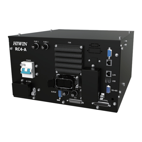
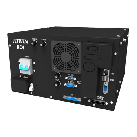
Hiwin HIMC Modbus TCP User manual

www.hiwinmikro.tw
User Guide
HIMC Modbus TCP

HIWIN Modbus TCP User Guide Revision History
Revision History
Release Date
Version
Applicable Software Version
Revision Contents
April 10th, 2018
0.1
iA Studio 1.0.2461.0
First edition.

HIWIN Modbus TCP User Guide Table of Contents
Table of Contents
1. Overview···············································································································1-1
1.1 Introduction of HIMC Modbus TCP········································································1-2
2. Communication interface of HIMC Modbus TCP·····························································2-1
2.1 Communication interface·····················································································2-2
3. Functions of HIMC Modbus TCP·················································································3-1
3.1 Data storage ····································································································3-2
3.2 Function codes ·································································································3-2
3.3 Exception codes································································································3-3
3.4 Data type·········································································································3-3
4. Register Map··········································································································4-1
4.1 Coils···············································································································4-2
4.2 Discrete inputs··································································································4-2
4.3 Input registers···································································································4-2
4.4 Holding registers·······························································································4-2
4.4.1 Axis·············································································································4-3
4.4.2 System call ···································································································4-5
4.4.3 Controller information······················································································4-6
4.4.4 GPIO···········································································································4-7
4.4.5 HMPL task····································································································4-8
4.4.6 User table·····································································································4-9
4.4.7 User-defined parameters················································································ 4-10
4.4.8 Undefined registers·······················································································4-10

HIWIN Modbus TCP User Guide Table of Contents
(This page is intentionally left blank.)

HIWIN Modbus TCP User Guide Overview
HIWIN MIKROSYSTEM Corp. 1-2
MH02UE01-1804
1.1 Introduction of HIMC Modbus TCP
HIWIN Motion Controller (HIMC) supports Modbus TCP communication protocol. Users are allowed to
access HIMC via Modbus TCP to read or write parameters of axis, system call, controller information, etc.

HIWIN MIKROSYSTEM Corp. 2-1
2. Communication interface of HIMC Modbus TCP
0000000 00000000000
2. Communication interface of HIMC Modbus TCP·····························································2-1
2.1 Communication interface·····················································································2-2

HIWIN Modbus TCP User Guide Communication Interface Of HIMC Modbus TCP
HIWIN MIKROSYSTEM Corp. 2-2
MH02UE01-1804
2.1 Communication interface
Connectors CN3 and CN4 are provided for communication with PC or human machine interface (HMI) via
Modbus TCP.
Figure 2.1.1
Information of connectors CN3 and CN4 is as below.
Table 2.1.1
Item Setting
CN3
CN4
IPAddress 169.254.188.21 169.254.188.20
Port 502
The simulator provided in HIMC can also be accessed via Modbus TCP. Information needed when
accessing HIMC simulator is as below.
Table 2.1.2
Item
Setting
Simulator*1
IPAddress 127.0.0.1
Port 502
Note:
1. Before accessing HIMC simulator via Modbus TCP, please ensure the connection with HIMC simulator is
established. For how to connect to HIMC simulator, please refer to section 2.1.3 Connecting to the simulator
in iA Studio User Guide.
CN3
CN4

HIWIN MIKROSYSTEM Corp. 3-1
3. Functions of HIMC Modbus TCP
000 00
3. Functions of HIMC Modbus TCP·················································································3-1
3.1 Data storage ····································································································3-2
3.2 Function codes ·································································································3-2
3.3 Exception codes································································································3-3
3.4 Data type·········································································································3-3

HIWIN Modbus TCP User Guide Functions Of HIMC Modbus TCP
HIWIN MIKROSYSTEM Corp. 3-2
MH02UE01-1804
3.1 Data storage
Data in standard Modbus are stored in four different tables. Register assignment of HIMC is as below.
Table 3.1.1
Table Name
Coil/Register Address
Data Size
Attribute
Coils 0x00000 - 0x65535 1 bit Read/Write
Discrete Inputs 1x00000 - 1x65535 1 bit Read-only
Input Registers 3x00000 - 3x65535 16 bits Read-only
Holding Registers 4x00000 - 4x65535 16 bits Read/Write
3.2 Function codes
Supported function codes in HIMC are as below.
Table 3.2.1
Function Code
Description
01 (01 hex) Reads coils.
02 (02 hex) Reads discrete inputs.
03 (03 hex) Reads input registers.
04 (04 hex) Reads holding registers.
05 (05 hex) Writes single coil.
06 (06 hex) Writes single holding register.
15 (0F hex) Writes multiple coils.
16 (10 hex) Writes multiple holding registers.

HIWIN Modbus TCP User Guide Functions Of HIMC Modbus TCP
HIWIN MIKROSYSTEM Corp. 3-3
MH02UE01-1804
3.3 Exception codes
When a request is received but cannot be processed, an exception response with an exception code will
be sent from HIMC. Supported exception codes in HIMC are as below.
Table 3.3.1
Exception Code
Definition
Description
01 (01 hex) Illegal function code An unsupported function code is requested.
For example, function
code 20 (14 hex) is specified in a request.
02 (02 hex) Illegal data address The requested register is not allowable. For example, for a controller
with 100 registers, the controller will reply exception code 0
2 if a
request with starting address 96 and register length 5 is received.
03 (03 hex) Illegal data value
The value specified in a request is not allowable. For example, the
initial address of a parameter is 0 and it occupies two registers. If a
request with starting address 1, or starting address 0 and register
length 1 is received to read or write the parameter, the controller will
reply exception code 03.
3.4 Data type
Parameters in HIMC are of different data types. Data types in HIMC are as below.
Table 3.4.1
Data Type
Data Size
Range
int8_t 8 bits –128 ~ 127
uint8_t 8 bits 0 ~ 255
int16_t 16 bits –32,768 ~ 32,767
uint16_t 16 bits 0 ~ 65,535
int32 32 bits –2,147,483,648 ~ 2,147,483,647
uint32 32 bits 0 ~ 4,294,967,295
float 32 bits 3.4E +/- 38 (7-digit)
double 64 bits 1.7E +/- 308 (15-digit)
Parameter data are stored in respective registers according to data types. Users need to follow the
instructions described below to read parameter data.

HIWIN Modbus TCP User Guide Functions Of HIMC Modbus TCP
HIWIN MIKROSYSTEM Corp. 3-4
MH02UE01-1804
int8_t, uint8_t, int16_t and uint16_t
Parameters of data types int8_t, uint8_t, int16_t and uint16_t are used for digital inputs or outputs
and controller status. The parameter data are stored as below.
Value
Register N
17 (0x0011)
( 00000000 00010001 ) 0x0011
( 00000000 00010001 )
int32_t and uint32_t
Parameters of data types int32_t and uint32_t are used for digital inputs or outputs and controller
status. The parameter data are stored as below.
Value
Register N (Start)
Register N+1 (End)
2097169 (0x00200011)
( 00000000 00100000 00000000 00010001 ) 0x0011
( 00000000 00010001 ) 0x0020
( 00000000 00100000 )
float
If parameter data types are float, the parameter data are stored as below.
Value
Register N (Start)
Register N+1 (End)
0.85
(0x3F59999A) 0x999A 0x3F59
double
If parameter data types are double, the parameter data are stored as below.
Value
Register N (Start)
Register N+1
Register N+2
Register N+3 (End)
0.85
(0x3FEB333333333333) 0x3333 0x3333 0x3333 0x3FEB

HIWIN MIKROSYSTEM Corp. 4-1
4. Register Map
00000000 0000000000
4. Register Map··········································································································4-1
4.1 Coils···············································································································4-2
4.2 Discrete inputs··································································································4-2
4.3 Input registers···································································································4-2
4.4 Holding registers·······························································································4-2
4.4.1 Axis·············································································································4-3
4.4.2 System call ···································································································4-5
4.4.3 Controller information······················································································4-6
4.4.4 GPIO···········································································································4-7
4.4.5 HMPL task····································································································4-8
4.4.6 User table·····································································································4-9
4.4.7 User-defined parameters················································································ 4-10
4.4.8 Undefined registers·······················································································4-10

HIWIN Modbus TCP User Guide Register Map
HIWIN MIKROSYSTEM Corp. 4-2
MH02UE01-1804
4.1 Coils
Registers for coils are not defined. Users are allowed to use these registers freely.
4.2 Discrete inputs
Registers for discrete inputs are not defined. Users are allowed to use these registers freely.
4.3 Input registers
Registers for input registers are not defined yet. Users are allowed to use these registers freely.
4.4 Holding registers
Registers for holding registers are used for parameters described as below.
Table 4.4.1
Category
Description
Axis Monitors status and sets parameters of each axis.
System Call Executes system calls, such as emergency stop, jog, relative motion, etc.
Controller Information Controller information
GPIO Controls general-purpose inputs or outputs (GPIO).
HMPL Task Reads task status and runs task.
User Table Reads HIMC User Table.
User-defined Parameters Some registers are reserved for user-defined parameters. Users can assign
desired parameters to registers.
Undefined Registers Some registers are not defined yet. Users are allowed to use these registers
freely.
Note:
For assigning desired parameters to registers, please refer to 4.10 Modbus manager in iA Studio User Guide.

HIWIN Modbus TCP User Guide Register Map
HIWIN MIKROSYSTEM Corp. 4-3
MH02UE01-1804
4.4.1 Axis
Users can monitor status and set parameters of each axis by reading or writing the registers assigned for
Axis. There are 32 axes in Axis.
Table 4.4.1.1
Register
Address
*1
Parameter
Data
Type
*2
Attribute Description Unit*3
0
Motion status uint32_t Read-only
Displays the motion status of axis N.
Bit 0 The axis is enabled.
Bit 1 The axis is moving.
Bit 2 The axis is in-position.
Bit 3 The axis is synchronized.
Bit 4 The axis is grouped.
-
1
2
Fault status uint32_t Read-only
Displays the fault status of axis N.
Bit 0 Error stop
Bit 1 Drive fault
Bit 2 Position error too big
Bit 3 Right hardware limit is reached.
Bit 4 Left hardware limit is reached.
Bit 5 Right software limit is reached.
Bit 6 Left software limit is reached.
-
3
4
Position feedback float Read-only Displays the feedback position of axis N. m or rad
5
6 Velocity feedback float Read-only Displays the feedback velocity of axis N. m/s
or rad/s
7
8 Acceleration
feedback float Read-only Displays the feedback acceleration of axis N. m/s2
or rad/s2
9
10
Max. profile velocity float Read/Write Sets or displays the velocity of axis N. m/s
or rad/s
11
12 Max. profile
acceleration float Read/Write Sets or displays the acceleration of axis N. m/s2
or rad/s2
13
14 Max. profile
deceleration float Read/Write Sets or displays the deceleration of axis N. m/s2
or rad/s2
15
16 Max. profile jerk float Read/Write Sets or displays the jerk of axis N. m/s3
or rad/s3
17
18 Smooth time float Read/Write Sets or displays the smooth factor of axis N. sec
19
20 P2P dwell time float Read/Write Sets or displays the dwell time of axis N. sec
21
22 P2P position 1 float Read/Write Sets or displays position 1 of axis N.
Note: Position 1 of point-to-point motion m or rad
23

HIWIN Modbus TCP User Guide Register Map
HIWIN MIKROSYSTEM Corp. 4-4
MH02UE01-1804
Register
Address
*1
Parameter
Data
Type
*2
Attribute Description Unit*3
24 P2P position 2 float Read/Write Sets or displays position 2 of axis N.
Note: Position 2 of point-to-point motion m or rad
25
26 Relative distance float Read/Write
Sets or displays the relative distance of axis N.
Note: Relative distance is the moving distance
when performing relative motion.
Use system call to perform relative motion.
m or rad
27
28 P2P repeat int8_t Read/Write
Sets to perform point-to-point motion repeatedly
on axis N. Or displays if point-to-point motion is
repeatedly performed on axis N.
Bit 0 0: Do not repeat point-to-point motion.
1: Repeats point-to-point motion.
Note: Use system call to perform point-to-point
motion.
-
29 Select axis int8_t Read/Write
Sets axis N as selected axis or displays if axis N is
selected.
Bit 0 0: Cancels the selected axis.
1: Selects axis.
Note: When using system call to perform motion
control, motion control will only be performed on
the selected axis.
-
30 Axis enable/disable int8_t Read/Write
Enables or disables axis N. Or displays if axis N is
enabled or disabled.
Bit 0 0: Axis N is disabled.
1: Axis N is enabled.
-
31 Clear error stop int8_t Write Clears the fault status of axis N.
Bit 0 1: Clears fault status.
-
32 Set zero int8_t Write
Sets the current position of axis N as zero
position.
Bit 0 1: Sets current position as zero position.
-
Note:
1. The register address of the parameters of each axis: Register address + 256 * N (Nmax = 31)
2. The default data types of some parameters are float.
3. The unit, linear unit or rotary unit is decided according to the setting in iA Studio.

HIWIN Modbus TCP User Guide Register Map
HIWIN MIKROSYSTEM Corp. 4-5
MH02UE01-1804
4.4.2 System call
Users can perform motion control on axes by writing the registers assigned for System Call. System Call
includes motion control functions such as emergency stop, jog, relative motion, etc. The registers
assigned for System Call are as below.
Table 4.4.2.1
Register
Address
Parameter Data Type Attribute Description*1
8192 Emergency stop int8_t Write
Performs emergency stop on all axes and disables all
axes.
Bit 0 1: Emergency stop
8193 Stop all int8_t Write Stops motions on all axes.
Bit 0 1: Stops motions on all axes.
8194 Stop int8_t Write Stops motion on the selected axis.
Bit 0 1: Stops motion on the selected axis.
8195 Jog + int8_t Write Performs jog in positive direction on the selected axis.
Bit 0
1: Performs jog in positive direction on the
selected axis.
8196 Jogs - int8_t Write Performs jog in negative direction on the selected axis.
Bit 0
1: Performs jog in negative direction on the
selected axis.
8197 Move relative int8_t Write Performs relative motion on the selected axis.
Bit 0
1: Performs relative motion on the selected
axis.
8198 P2P P1 int8_t Write Moves the selected axis to position
1. (This function is
currently not available.)
Bit 0 1: Moves the selected axis to position 1.
8199 P2P P2 int8_t Write Moves the selected axis to position
2. (This function is
currently not available.)
Bit 0 1: Moves the selected axis to position 2.
Note:
To perform functions mentioned in table 4.4.2.1 on the selected axis, please first select axis by writing the assigned
register. Motion control parameters of each axis can be set by writing registers assigned for Axis.

HIWIN Modbus TCP User Guide Register Map
HIWIN MIKROSYSTEM Corp. 4-6
MH02UE01-1804
4.4.3 Controller information
Users can monitor controller information such as controller status and error code by reading the registers
assigned for Controller Information. The registers assigned for Controller Information are as below.
Table 4.4.3.1
Register
Address
Parameter Data Type Attribute Description
8208
Controller
status*1 uint32_t Read-only
Displays controller status. For what each value means,
please refer to below.
0 Initializing
1 Busy
2 Synchronous
Controller is ready to perform motion control.
3 Asynchronous
Controller is not ready to perform motion control.
4 An error occurs in the controller.
8209
8210
Error code*2 uint32_t Read-only Displays the latest HIMC error code.
8211
Note:
1. For related information of controller status, please refer to section 1.4 Main screen in iA Studio User Guide.
For how the LED indicator reacts to each status, please refer to section 1.6 LED indicator in HIMC Installation
Guide.
2. The error code is stored in decimal format. Please convert to hexadecimal format to search for its description in
section 5. Appendix in iA Studio User Guide.

HIWIN Modbus TCP User Guide Register Map
HIWIN MIKROSYSTEM Corp. 4-7
MH02UE01-1804
4.4.4 GPIO
Users can monitor the statuses of general-purpose inputs or outputs (GPIO) or set general-purpose
outputs by reading or writing the registers assigned for GPIO. HIMC provides 8 general-purpose inputs
(GPI1~GPI8) and 8 general-purpose outputs (GPO1~GPO8). The registers assigned for GPIO are as
below.
Table 4.4.4.1
Register
Address
Parameter Data Type Attribute Description
8272 GPI status int8_t Read-only
Displays the status of GPI (1~8).
Bit 0
0: GPI1 is OFF.
1: GPI1 is ON.
…
…
Bit 7 0: GPI8 is OFF.
1: GPI8 is ON.
8273 GPO status int8_t Read/Write
Sets GPO (1~8) or displays the status of GPO (1~8).
Bit 0 0: GPO1 is OFF.
1: GPO1 is ON.
…
…
Bit 7 0: GPO8 is OFF.
1: GPO8 is ON.

HIWIN Modbus TCP User Guide Register Map
HIWIN MIKROSYSTEM Corp. 4-8
MH02UE01-1804
4.4.5 HMPL task
Users can monitor HMPL task status or run HMPL task by reading or writing the registers assigned for
HMPL Task. HIMC provides 64 tasks (task 0 to task 63). The registers assigned for HMPL Task are as
below.
Table 4.4.5.1
Register
Address
*1
Parameter Data Size Attribute Description
8448 Task status
(Task 0) int8_t Read-only
Displays the status of task.
Bit 0 Task is imported to RAM.
Bit 1 Task is running.
Bit 2 Task is running in debug mode.
Bit 3
Task is paused.
Bit 4 Error occurs when running task.
Bit 5 Task has been modified.
Bit 6 Error occurs when importing task.
8449 Task start/stop
(Task 0) int8_t Read/Write
Runs or stops task.
Bit 0 0: Stops task.
1: Runs task.
Note:
1. The register address of the parameters of each task: register address + N * 2 (Nmax = 63)
Table of contents
Other Hiwin Controllers manuals
Popular Controllers manuals by other brands

thomann
thomann the t.racks DSP 4x4 Mini Amp manual

Honeywell
Honeywell Touchpoint Plus Technical handbook

Honeywell
Honeywell CIPer 50 user guide

Johnson Controls
Johnson Controls FMS-2000C installation guide

Invertek Drives
Invertek Drives OPTIDRIVE E3 Series quick start guide

Texas Instruments
Texas Instruments TMS320C6000 DSP reference guide

Mitsubishi
Mitsubishi Q64AD installation manual

Multiplex
Multiplex ROXXY MSB 45A operating instructions

Simply Automated
Simply Automated DKIT-02 Getting started

Velleman
Velleman TRCV3 manual

DTM System
DTM System miniR2 Series Assembly and operating manual

Danfoss
Danfoss vlt soft starter mcd 500 Service manual