Assembly Instructions
Linear Tables HT-L
HTL-01-0-EN-1905-MA
Contents
Contents
1. General information ........................................................4
1.1 About these assembly instructions 4
1.2 Depictions used in these assembly instructions 5
1.3 Warranty and liability 7
1.4 Manufacturer’s details 7
1.5 Copyright 7
1.6 Product monitoring 7
2. Basic safety notices........................................................8
2.1 Intended use 8
2.2 Reasonably foreseeable misuse 8
2.3 Conversions and modifications 8
2.4 Residual risks 8
2.5 Personnel requirements 9
2.6 Protective equipment 9
2.7 Labels on the linear table 9
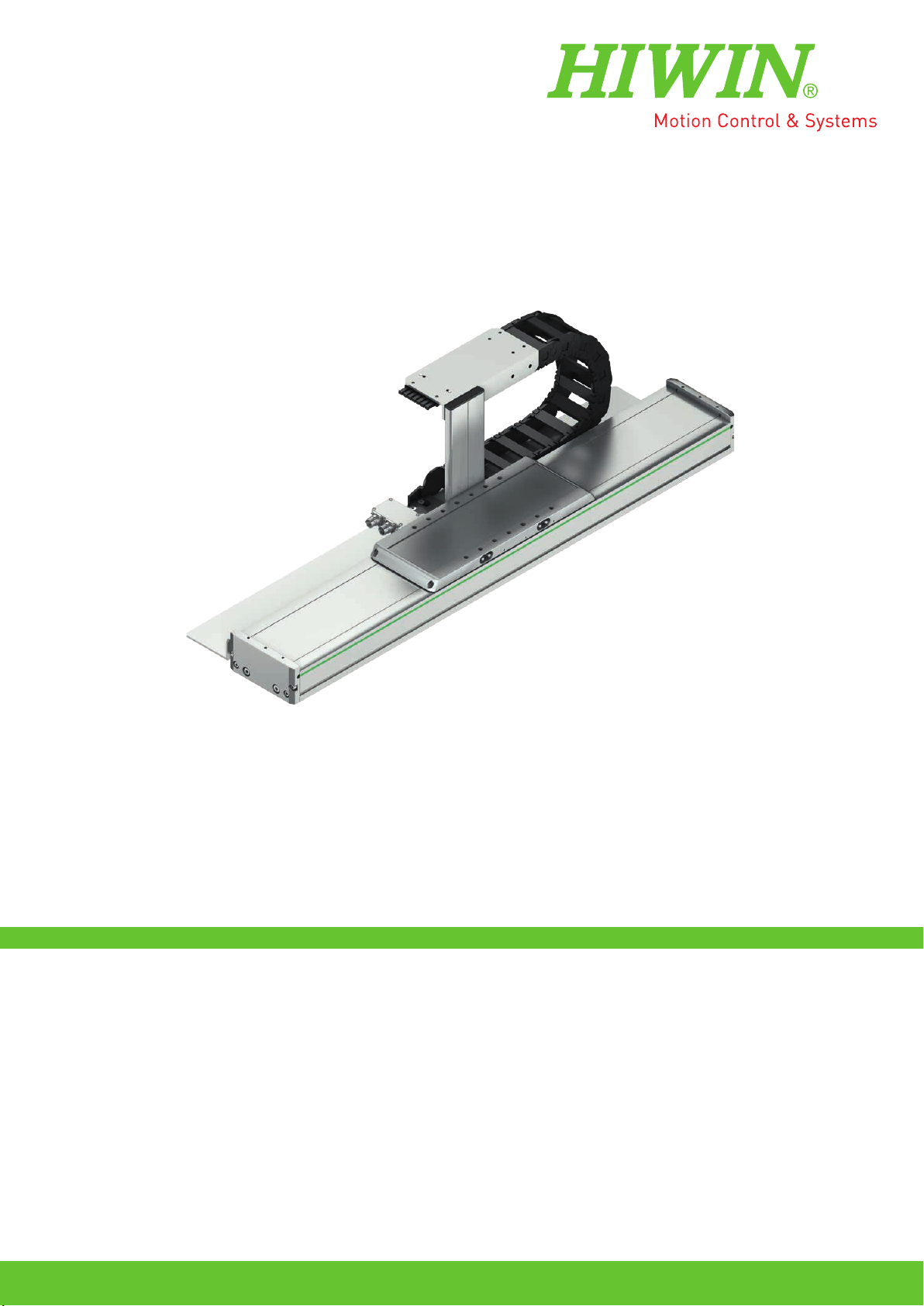
3. Description of the linear tables HT-L ...............................10
3.1 Field of application 10
3.2 Ambient conditions 10
3.3 Main components 10
3.4 Functional description 11
3.5 Order code for linear tables HT-L 12
4. Options of the linear tables............................................13
4.1 Stroke length 13
4.2 Cover 13
4.3 Carriage 14
4.4 Limit switches 14
4.5 Distance measuring system 15
4.6 Hall sensor 18
4.7 Connection interface and energy supply 19
4.8 Energy chain 20
5. Transport and installation....................................................21
5.1 Delivery 21
5.2 Transport to the installation site 21
5.3 Requirements at the installation site 21
5.4 Storage 22
5.5 Unpacking and installing 22
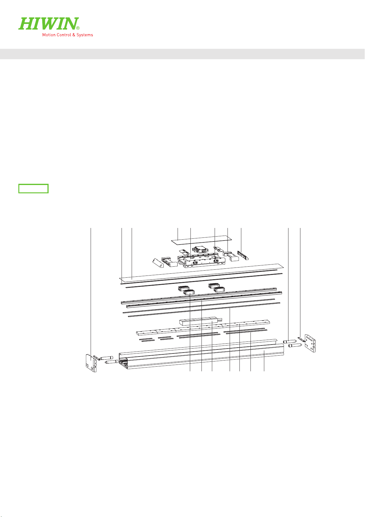
6. Assembly and connection ....................................................24
6.1 Assembling the linear tables HT-L 25
6.2 Mounting the imposed load 30
6.3 Mounting the limit switches 31
6.4 Mounting the damping element 31
6.5 Setting the switching distance 32
6.6 Electrical connection 33
7. Maintenance and cleaning.................................................... 37
7.1 Lubrication 38
7.2 Cleaning the linear table 40
7.3 Replacing the cover strip 41
7.4 Visual examination of electrical componentry 43
8. Faults ................................................................................44
8.1 HT-L linear table system malfunctions 44
8.2 Faults during operation with drive amplifier 45
9. Disassembly.................................................................46
10. Disposal ......................................................................48
11. Appendix 1: Accessories and spare parts.........................49
11.1 Clamping profiles 49
11.2 T nut 50
11.3 Centring sleeve 50
11.4 Groove cover 51
11.5 Limit switch 51
11.6 Extension cable for limit switch 52
11.7 Damping element 52
11.8 Cover strip 52
11.9 Magnetic strip 53
11.10 Cover strip deflection 53
11.11 Buffer stop 54
11.12 Motor cable 54
11.13 Encoder cable for incremental distance measuring system 55
11.14 Encoder cable for absolute distance measuring system 56
11.15 Separators for energy chain 57
11.16 HIWIN lubricants 57
11.17 HIWIN grease nipple 58
11.18 Lubrication fittings and push-in fittings 58
12. Appendix 2: Declaration of Incorporation.........................60