Hiwin HM-S User manual

Assembly Instructions
Linear Axes HM-S
Linear Tables HT-S
www.hiwin.de
Valid from serial no. HSN 000 000 000 1

HIWIN GmbH
Brücklesbünd 1
77654 Offenburg
Germany
Phone +49 (0) 7 81 9 32 78 - 0
Fax +49 (0) 7 81 9 32 78 - 90
www.hiwin.de
All rights reserved.
Complete or partial reproduction
is not permitted without our permission.
These assembly instructions are protected by copyright.
Any reproduction, publication in whole or in part,
modification or abridgement requires the written approval
of HIWIN GmbH.

Assembly Instructions
Linear Axes HM-S and HT-S
HMS_HTS-01-0-EN-1905-MA
Contents
Contents
1. General information ........................................................4
1.1 About these assembly instructions 4
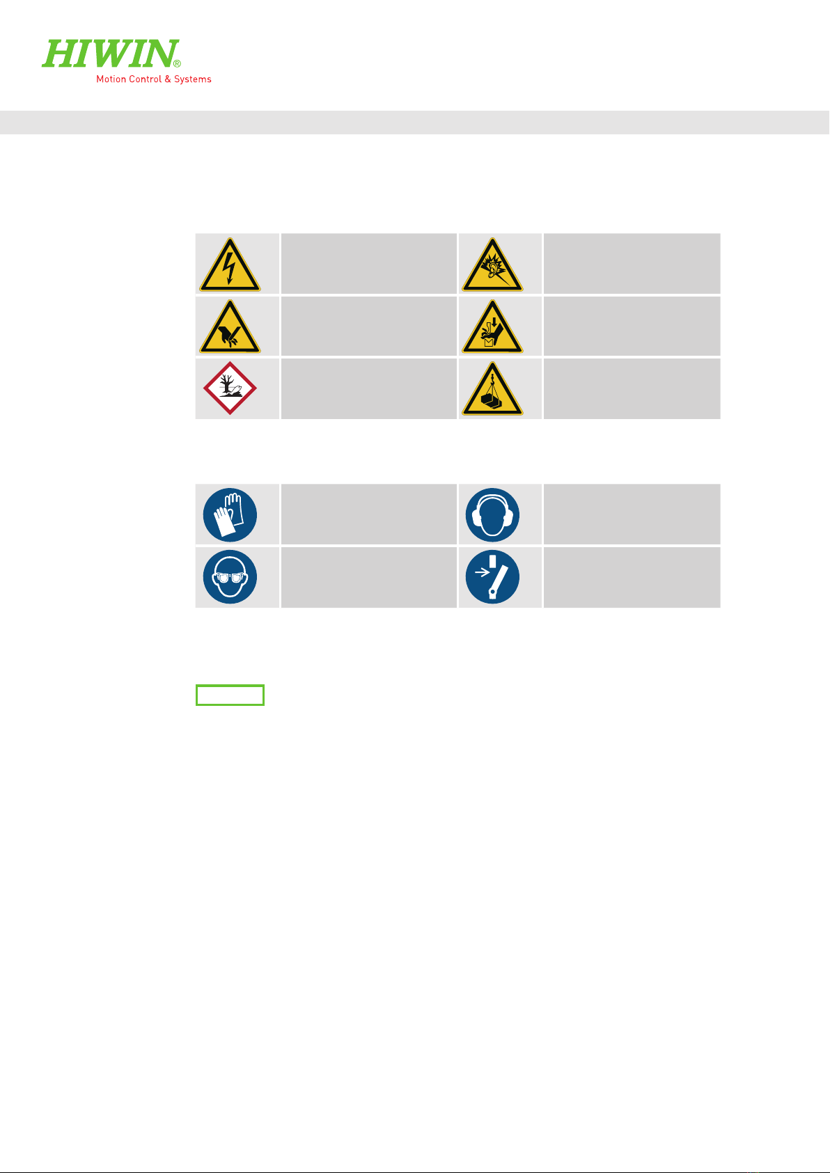
1.2 Depictions used in these assembly instructions 5
1.3 Warranty and liability 7
1.4 Manufacturer’s details 7
1.5 Copyright 7
1.6 Product monitoring 7
2. Basic safety notices........................................................8
2.1 Intended use 8
2.2 Reasonably foreseeable misuse 8
2.3 Conversions and modifications 8
2.4 Residual risks 8
2.5 Personnel requirements 9
2.6 Protective equipment 9
2.7 Labels on the linear axis system 9
3. Description of the HM-S linear modules and
HT-S linear tables .........................................................10
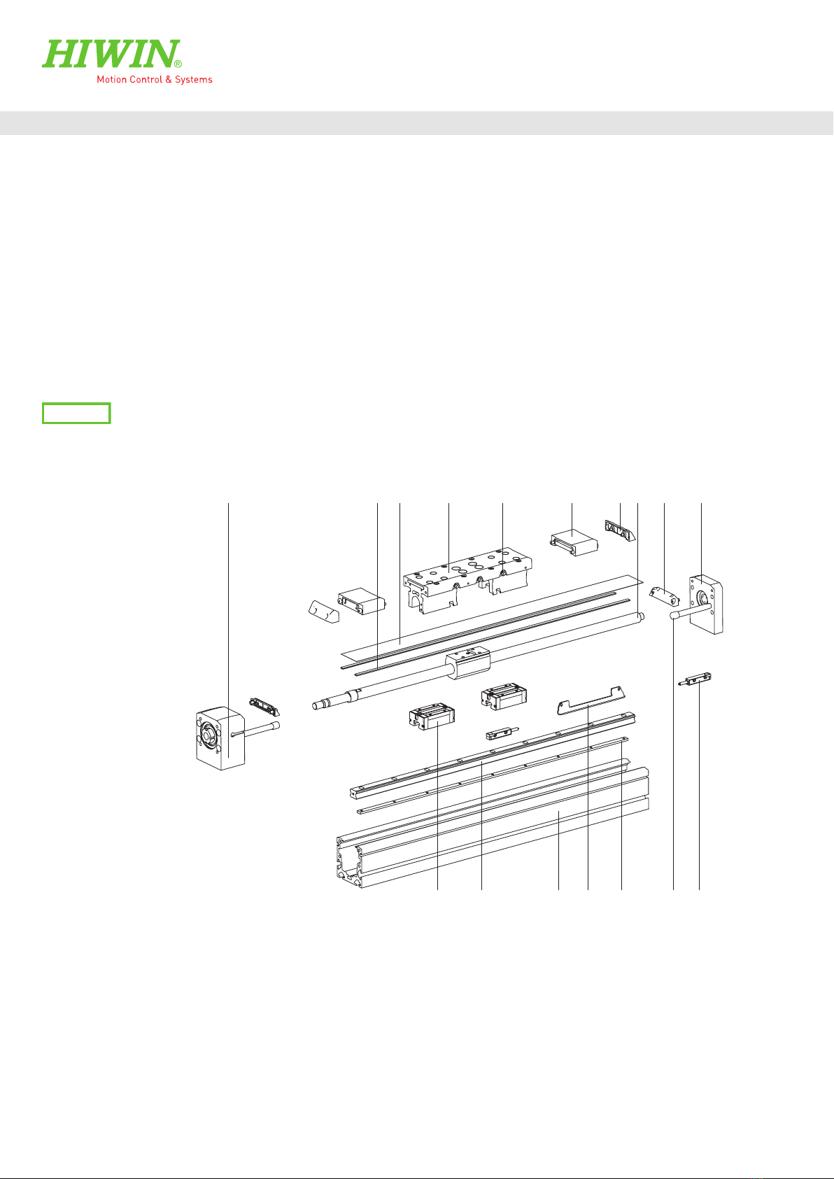
3.1 HM-S linear module 10
3.2 HT-S linear table 13
4. Options of the HM-S linear modules and HT-S linear tables 16
4.1 Stroke length 16
4.2 Cover 17
4.3 Carriage 17
4.4 Limit switches 17
4.5 Positioning measuring system 18
4.6 Drive interfaces 21
4.7 Motor 21
4.8 Spindle support 21
5. Transport and installation..............................................22
5.1 Delivery 22
5.2 Transport to the installation site 22
5.3 Requirements at the installation site 22
5.4 Storage 23
5.5 Unpacking and installing 23
6. Assembly and connection ..............................................25
6.1 Assembling the linear axes 26
6.2 Mounting the imposed load 34
6.3 Mounting the limit switches 35
6.4 Mounting the damping element 36
6.5 Setting the switching distance 37
6.6 Mounting the drive unit on the HM-S linear axis 38
6.7 Mounting the drive unit on the HT-S linear table 46
6.8 Electrical connection 53
7. Maintenance and cleaning .............................................55
7.1 Lubrication 56
7.2 Cleaning the linear axis 61
7.3 Replacing the cover strip 61
7.4 Visual examination of electrical componentry 66
8. Faults.......................................................................... 67
8.1 Linear axis and linear axis system malfunctions 67
8.2 Motor malfunctions 68
8.3 Faults during operation with drive amplifier 68
9. Disassembly.................................................................69
10. Disposal ......................................................................71
11. Appendix 1: Drive adapter..............................................72
11.1 Motor adapter of the HM-S linear modules and
the HT-S linear tables 72
11.2 Dimensions of motor adapter of the HM-S linear
modules and the HT-S linear tables 76
12. Appendix 2: Accessories................................................ 86
12.1 Clamping profiles 86
12.2 T nut 87
12.3 Centring sleeve 88
12.4 Groove cover 88
12.5 Limit switch 89
12.6 Extension cable for limit switch 89
12.7 Damping element 90
12.8 Positioning measuring system HIWIN MAGIC 90
12.9 Cover strip 91
12.10 Magnetic strip 91
12.11 Cover strip deflection for linear modules HM-S 92
12.12 Cover strip deflection for linear tables HT-S 92
12.13 Buffer stop 93
12.14 Toothed belt for belt drive RT 93
12.15 HIWIN lubricants 94
12.16 HIWIN grease nipples 95
12.17 Lubrication fittings and push-in fittings 95
13. Appendix 3: Declaration of Incorporation.........................97

4
General information
Assembly Instructions
Linear Axes HM-S and HT-S
HMS_HTS-01-0-EN-1905-MA
1. General information
1.1 About these assembly instructions
These assembly instructions are intended for planners, developers and operators of systems who plan for and install HM-S
and HT-S linear axes as machine elements. They are also intended for persons who perform the following tasks in connection
with the above mentioned axes:
Transportation
Assembly
Electrical connection including connection to the higher-level control system
Integration into a security system
Retrofitting or upgrading
Setup
Commissioning
Operation
Maintenance
Cleaning
Troubleshooting and error elimination
Shutdown, disassembly and disposal
Version Date Notes
01-0 May 2019 Initial creation of this document
Table 1.1 Version management
1.1.1 Version management
1.1.2 Requirements
We assume that
operating personnel are trained in the safe operation practices for HM-S and HT-S linear axes and have read and under-
stood these assembly instructions in full;
maintenance personnel maintain and repair the HM-S and HT-S linear axes in such a way that they pose no danger to
people, property or the environment.
1.1.3 Availability
These assembly instructions must remain constantly available to all persons who work with or on the HM-S and HT-S linear
axes.

General information
5
Assembly Instructions
Linear Axes HM-S and HT-S
HMS_HTS-01-0-EN-1905-MA
1.2 Depictions used in these assembly instructions
1.2.1 Instructions
Instructions are indicated by triangular bullet points in the order in which they are to be carried out.
Results of the actions carried out are indicated by ticks.
Example:
Produce appropriate mounting holes on the mounting surface if not already present.
Clean mounting surface and position linear axis on it
With the help of T nuts and clamping profiles fix the linear axis.
Linear axis is mounted.
1.2.2 Lists
Lists are indicated by bullet points.
Example:
Linear axes must not be operated:
Outdoors
In potentially explosive atmospheres
…
1.2.3 Depiction of safety notices
Safety notices are always indicated using a signal word and sometimes also a symbol for the specific risk (see Section 1.2.4,
“Symbols used”).
The following signal words and risk levels are used:
Imminent danger!
Noncompliance with the safety notices will result in serious injury or death!
DANGER!
Potentially dangerous situation!
Noncompliance with the safety notices runs the risk of serious injury or death!
WARNING!
Potentially dangerous situation!
Noncompliance with the safety notices runs the risk of slight to moderate injury!
CAUTION!
Potentially dangerous situation!
Noncompliance with the safety notices runs the risk of damage to property or environmental pollution!
ATTENTION!

6
General information
Assembly Instructions
Linear Axes HM-S and HT-S
HMS_HTS-01-0-EN-1905-MA
1.2.4 Symbols used
The following symbols are used in these assembly instructions and on the linear axes:
Table 1.2 Warning signs
Table 1.3 Mandatory signs
1.2.5 Information
NOTE
Describes general information and recommendations.
Warning of risk of hearing damage!
Warning of crushing!
Warning of danger from suspended
loads!
Warning of dangerous electrical voltage!
Warning of cutting injuries!
Substance hazardous to the
environment!
Wear hearing protection!
Isolate before work!
Wear protective gloves!
Wear safety goggles!

General information
7
Assembly Instructions
Linear Axes HM-S and HT-S
HMS_HTS-01-0-EN-1905-MA
1.3 Warranty and liability
The manufacturer’s “General conditions of sale and delivery” apply.
1.4 Manufacturer’s details
Address HIWIN GmbH
Brücklesbünd 1
D-77654 Offenburg
Phone +49 (0) 781 / 9 32 78 - 0
Technical customer service +49 (0) 781 / 9 32 78 - 77
Fax +49 (0) 781 / 9 32 78 - 90
Technical customer service fax +49 (0) 781 / 9 32 78 - 97
E-mail [email protected]
Website www.hiwin.de
Table 1.4 Manufacturer’s details
1.5 Copyright
These assembly instructions are protected by copyright. Any reproduction, publication in whole or in part, modification or
abridgement requires the written approval of HIWIN GmbH.
1.6 Product monitoring
Please inform HIWIN, the manufacturer of the HM-S and HT-S linear axes of:
Accidents
Potential sources of danger in the linear axes
Anything in these assembly instructions which is difficult to understand

8
Basic safety notices
Assembly Instructions
Linear Axes HM-S and HT-S
HMS_HTS-01-0-EN-1905-MA
2. Basic safety notices
This chapter serves to ensure the safety of everyone working with HM-S and HT-S linear axes and those who assemble,
install, operate, maintain or disassemble them. Non-compliance with the following information results in dangerous
working conditions.
WARNING!
2.1 Intended use
The HM-S and HT-S linear axes combine guiding and drive functions in the one compact unit. They are designed for the
precise positioning in terms of time and location of fixed mounted loads within an automated system. It is specifically ideal
for applications requiring high precision.
In the case of vertical assembly, a suitable clamping or braking device must be provided in order to prevent unintended
lowering of the load.
All HM-S and HT-S linear axes may only be used for the intended purpose as described.
All HM-S and HT-S linear axis sizes are subject to performance limits (see catalogue „Linear Axes and Axis Systems
HX”). These performance limits may not be exceeded during operations.
HM-S and HT-S linear axes must not be operated in potentially explosive atmospheres.
HM-S and HT-S linear axes may only be used and operated indoors.
HM-S and HT-S linear axes form part of a complete system. Personal safety must therefore be safeguarded beyond the
concept for this complete system.
Proper use of the HM-S and HT-S linear axes includes observing the assembly instructions and following the mainte-
nance and repair specifications.
Use of the HM-S and HT-S linear axes for any other purpose shall be considered improper use.
The HM-S and HT-S linear axes are delivered as a system (guiding/drive). Therefore observe the whole documentation for this
system. The provided documentation may vary depending on the linear axis type.
2.2 Reasonably foreseeable misuse
HM-S and HT-S linear axes must not be operated:
outdoors
in potentially explosive atmospheres
2.3 Conversions and modifications
Conversions or modifications to the HM-S and HT-S linear axes are not permitted!
2.4 Residual risks
During normal operation, there are no residual risks associated with the HM-S and HT-S linear axes because they form part of
the complete system and the operator must safeguard personal safety beyond the concept for this complete system. Warn-
ings about risks that may arise during maintenance and repair work are provided in the relevant sections.

Basic safety notices
9
Assembly Instructions
Linear Axes HM-S and HT-S
HMS_HTS-01-0-EN-1905-MA
Activity Qualification
Normal operation Trained personnel
Cleaning Trained personnel
Maintenance Trained specialist personnel of the operator or manufacturer
Repair Trained specialist personnel of the operator or manufacturer
Transportation Trained personnel
Assembly Trained specialist personnel
Disassembly Trained specialist personnel
Table 2.1 Personnel requirements
Operating phase Personal protective equipment
Normal operation No persons may remain at the HM-S and HT-S linear axes during normal opera-
tions. Persons near the HM-S and HT-S linear axes must wear the following
personal protective equipment depending on the travel speed:
Safety shoes
If necessary, hearing protection
All other operating phases
(cleaning, maintenance, resetting,
troubleshooting, repair)
The following personal protective equipment is needed for all other operating
phases of the HM-S and HT-S linear axes:
Safety shoes
If necessary, safety gloves and safety goggles
If necessary, hearing protection
Table 2.2 Personal protective equipment
Model No: HM060S010C0755L000ANNN
ID-No: 24-12345
S/N: S-123456789
Weight: 5kg
Mfg. date: 2015/03
HIWIN GmbH
Brücklesbünd 1
77654 Offenburg
Fig. 2.1 Type plate (example only)
2.5 Personnel requirements
Only authorised and competent persons may carry out work on the HM-S and HT-S linear axes! They must be familiar with
the safety equipment and regulations before starting work (see Table 2.1).
2.6 Protective equipment
2.6.1 Personal protective equipment
2.7 Labels on the linear axis system
The HM-S and HT-S linear axes bear the labels depicted in the following.
2.7.1 Type plate

10
Description of the HM-S linear modules and HT-S linear tables
Assembly Instructions
Linear Axes HM-S and HT-S
HMS_HTS-01-0-EN-1905-MA
3. Description of the HM-S linear modules and HT-S linear tables
3.1 HM-S linear module
3.1.1 Field of application
HIWIN HM-S linear modules with ballscrew are compact, flexible positioning modules. They are specifically ideal for applica-
tions requiring high precision and high feed forces.
3.1.2 Ambient conditions
Ambient conditions during operation: +5 to +40°C
Relative air humidity during operation: complying with IEC60721-3-3, Class 3k3, non-condensing
Climatic environmental conditions for transport and storage: ambient temperature: –20 to +50°C, non-condensing
Vacuum: it may not be operated in vacuum
3.1.3 Main components
[6] [7] [8][1]
[16] [15] [14][17] [12] [11][13]
[2] [3] [4] [5] [9] [10]
Fig. 3.1 Main components of the HM-S linear axis
Prevent condensation to avoid corrosion of the axis.
NOTE

Description of the HM-S linear modules and HT-S linear tables
11
Assembly Instructions
Linear Axes HM-S and HT-S
HMS_HTS-01-0-EN-1905-MA
Pos. Description Pos. Description
1Drive block 10 End plate
2Magnetic strip 11 Limit switch
3Steel cover strip 12 Stopping buffer
4Carriage 13 Threaded bar
5Grease nipple, 3 grease nipples on each side 14 Clamping element
6Cover strip deflection 15 Axis body of aluminium
7Carriage end piece 16 Profile rail
8Ballscrew 17 Block
9Clamp housing for cover strip
Table 3.1 Description of the main components of the HM-S linear module
3.1.4 Functional description
Ballscrew linear axes combine guiding and drive functions in the one compact unit. The forces and torques generated by the
moving load are transferred through the carriages into the linear guideway. The linear guideway also executes precise linear
movements with two blocks per carriage. The movements themselves are executed over a ballscrew whose spindle is driven
by an electric motor. The ballscrew converts the motor’s rotations into linear motion of the nut secured firmly to the carriage.
Fig. 3.2 Functional principle of the HM-S linear module

12
Description of the HM-S linear modules and HT-S linear tables
Assembly Instructions
Linear Axes HM-S and HT-S
HMS_HTS-01-0-EN-1905-MA
3.1.5 Order code for linear modules HM-S
Order code for linear modules HM-S (continuation)
1) Detailed information upon request or in the assembly instructions “HIWIN MAGIC Positioning Measuring Systems”
2) If no drive interface is selected, the order code ends at this position
3) All flange types can be found in Section 11.1 on Page 73 ff.
If no flange type is selected, the order code ends at this position
4) Suitable HIWIN motors can be found in the catalogue “Drives and Servo Motors”
5) Further reference switches on request
Clearance between
two carriages [mm]:
(000: One carriage only)
Carriage length:
S: Short
L: Long
Stroke length [mm]
Cover strip:
C: With steel cover strip
N: Without cover
HM 060 S010 C0755 L000
HIWIN linear module
Size (profile width):
040: 40mm
060: 60mm
080: 80mm
120: 120mm
Drive type:
S: Ballscrew
Spindle lead [mm]:
005/010: HM040S
005/010/016: HM060S
005/010/020: HM080S
010/020/032: HM120S
Motor4)
Flange type of motor3)
ANNRHW03 FRLS2020506A
Axis limit switches5):
N: Without limit switches
A: 2 × NC, 100mm cable, plug
C: 2× NC, 4 m open cable end
D: 2× NO, 5 m open cable end
Spindle supports:
N: Without spindle supports
1: One spindle support per side
(HM060/080/120)
2: Two spindle supports per side
(HM060/080/120)
3: Three spindle supports per side
(HM060/080/120)
Optional positioning measuring system1):
N: Without positioning measuring system
A: Positioning measuring system with
analogue signal
D: Positioning measuring system with
digital signal
Drive interface2):
N: Without
S: Straight
L: Left
R: Right
A Top
B: Bottom
NS LR AB

Description of the HM-S linear modules and HT-S linear tables
13
Assembly Instructions
Linear Axes HM-S and HT-S
HMS_HTS-01-0-EN-1905-MA
3.2 HT-S linear table
3.2.1 Field of application
HIWIN linear tables HT-S with ballscrew drive are particularly suitable for applications in which large loads need to be moved
with high precision. The integrated HIWIN ballscrews exhibit high lead accuracy and rigidity for precise positioning. Each size
comes with various spindle leads for the optimal solution to feed force and dynamic response requirements. Thanks to up to
four moving spindle supports per side, the method can be realised at full speed, even over long strokes.
3.2.2 Ambient conditions
Ambient conditions during operation: +5 to +40°C
Relative air humidity during operation: complying with IEC60721-3-3, Class 3k3, non-condensing
Climatic environmental conditions for transport and storage: ambient temperature: –20 to +50°C, non-condensing
Vacuum: it may not be operated in vacuum
3.2.3 Main components
[7] [8] [9][1]
[15] [14][16] [12][13]
[2] [3] [5][4] [6] [10] [11]
Fig. 3.3 Main components of the linear tables HT-S
Pos. Description Pos. Description
1End plate 9Ballscrew
2Magnetic strips 10 Clamp housing for cover strip
3Steel cover strip 11 Drive block
4Carriage cover 12 Stopping buffer
5Carriage 13 Threaded bars
6Grease nipple 14 Axis body of aluminium
7Cover strip deflection 15 Profile rails
8Carriage end piece 16 Block
Table 3.2 Description of the main components of the linear tables HT-S
Prevent forming of condensation to prevent corrosion of the axis.
NOTE

14
Description of the HM-S linear modules and HT-S linear tables
Assembly Instructions
Linear Axes HM-S and HT-S
HMS_HTS-01-0-EN-1905-MA
3.2.4 Functional description
Linear tables with ballscrew drive combine guiding and drive functions in the one compact unit. The forces and torques gen-
erated by the moving load are transferred through the carriages into the linear guideway. The linear guideways also execute
precise linear movements with four blocks per carriage. The movements themselves are executed over a ballscrew whose
spindle is driven by an electric motor. The ballscrew converts the motor’s rotations into linear motion of the nut secured
firmly to the carriage.
Fig. 3.4 Functional principle of the HT-S linear tables

Description of the HM-S linear modules and HT-S linear tables
15
Assembly Instructions
Linear Axes HM-S and HT-S
HMS_HTS-01-0-EN-1905-MA
3.2.5 Order code for linear tables HT-S
Order code for linear tables HT-S (continuation)
1) Detailed information in Section 4.5 or in the assembly instructions “HIWIN MAGIC Positioning Measuring Systems”
2) If no drive interface is selected, the order code ends at this position
3) All flange types can be found in Section 11.1 on Page 73 ff.
If no flange type is selected, the order code ends at this position
4) Suitable HIWIN motors can be found in the catalogue “Drives and Servo Motors”
5) Further reference switches on request
Carriage length:
S: Short
Stroke length [mm]
Cover strip:
C: With steel cover strip
N: Without cover strip
HT 150 S010 C1234 S
HIWIN linear table
Size (profile width):
100: 100mm
150: 150mm
200: 200mm
250: 250mm
Drive type:
S: Ballscrew Spindle lead [mm]:
005/010/016: HT100S
005/010/020: HT150S
005/010/025: HT200S
010/020/032: HT250S
Motor4)
Flange type of motor3)
ANNSHW05 FRLS2020506A
Axis limit switches5):
N: Without limit switches
A: 2 × NC, 100mm cable, plug
C: 2× NC, 4 m open cable end
D: 2× NO, 5 m open cable end
Spindle support:
N: Without spindle supports
1: One spindle support per side
2: Two spindle supports per side
3: Three spindle supports per side
4: Four spindle supports per side
Optional positioning measuring system1):
N: Without positioning measuring system
A: Positioning measuring system with analogue signal
D: Positioning measuring system with digital signal
Drive interface2):
N: None
S: Straight
L: Left
R: Right
A: Top
B: Bottom
NS LR AB

16
Options of the HM-S linear modules and HT-S linear tables
Assembly Instructions
Linear Axes HM-S and HT-S
HMS_HTS-01-0-EN-1905-MA
4. Options of the HM-S linear modules and HT-S linear tables
4.1 Stroke length
The stroke lengths for the linear axes can be set to the millimetre.
The maximum stroke lengths depending on the series and size are listed in Table 4.1.
Please bear in mind that the maximum possible stroke is shorter with the following options:
Longer carriages (HM-S: carriage type L)
Second carriage (HM-S)
Type with cover strip (owing to required cover strip deflections)
If necessary, spindle supports
Table 4.1 Maximum stroke
Model Axis Maximum stroke [mm]
Linear module HM040B 3,000
HM060B 5,500
HM080B 5,500
HM120B 5,500
Linear table HT100S 2,600
HT150S 3,000
HT200S 3,500
HT250S 3,800
4.1.1 Reserve stroke
The reserve stroke Lrequals the distance that can be travelled in addition to the stroke on both sides of the end positions
(stroke 0, stroke max) before the carriage reaches the mechanical end position (mechanical 0) at the installed dampers. The
reserve stroke for each axis size can be found in the catalogue„Linear Axes and Axis Systems HX“.
Fig. 4.1 Example reserve stroke on a linear axis
Reserve stroke Lr
Carriage position at mechanical 0
(buffer stop)
Carriage position at stroke 0
(sensor switching point)
Sensor switching point at stroke 0

Options of the HM-S linear modules and HT-S linear tables
17
Assembly Instructions
Linear Axes HM-S and HT-S
HMS_HTS-01-0-EN-1905-MA
4.2 Cover
An optional steel cover strip is available for all linear axis and double axis sizes. This cover strip is held in place with mag-
netic strips to prevent contaminants from entering the axis’s interior. Bear in mind that the carriage is longer on axes with
cover strip because of the required cover strip deflection.
4.3 Carriage
There are two carriage types available for the HM-S linear axis (carriage type S and L). The linear tables HT-S are equipped
with the carriage type S as standard. The carriages are equipped with mounting threads for mounting the imposed load.
These have additional counterbores that can take centring sleeves.
Fig. 4.2 Carriage with mounting threads
The typical applications for each of the linear modules’ carriage lengths are:
Short carriage (S)
For individual axes
Long carriage (L)
For very high torques (My, Mz)
For use in gantry systems (primarily for X-axis)
The optional cover strip cannot be retrofitted.
NOTE
4.4 Limit switches
The linear axes feature two inductive PNP or proximity switches that signal the end positions of the travel distance. The limit
switch cables can be routed either directly to the interface or into the mounting groove. The limit switches are available as
N/C or N/O contacts, with or without plug.
4.4.1 Limit switch dimensions
Fig. 4.3 Limit switch dimensions
8
Connection
LED indicator 270°
Threaded
mounting hole
2.5
Ø 3.2
Ø 2.9
40
20 10
4.5
8.1

18
Options of the HM-S linear modules and HT-S linear tables
Assembly Instructions
Linear Axes HM-S and HT-S
HMS_HTS-01-0-EN-1905-MA
4.4.2 Limit switch specifications
Properties N/C contact (25-000786) N/C contact (25-000787) N/O contact (25-000788)
Housing Rectangular
Dimensions (W × H × D) 8×8 × 40mm
Max. sensing range 2mm
Switching frequency 2,000Hz
Connection type Cable with M8, 3-pin plug,
100mm
Cable, 3-wire, 4m Cable, 3-wire, 5 m
Output type PNP
Electrical wiring DC 3-wire
Protection class IP67, IP681)
1) According to EN 60529
Table 4.2 General features of the limit switches
Mechanics/electronics N/C contact (25-000786) N/C contact (25-000787) N/O contact (25-000788)
Supply voltage 10 to 30VDC
Ripple
≤
10 % 1)
Voltage drop
≤
2 V 2)
Current consumption
≤
10 mA 3)
Time delay before availability
≤
100 ms
Hysteresis 5 to 15%
Repeatability
≤
2 % 4)
Temperature drift ±10%
EMC According to EN 60947-5-2
Continuous current Ia
≤
200 mA
Cable material PVC
Short-circuit protection Yes
Reverse polarity protection Yes
Power-up pulse protection Yes
Shock and vibration resistance 30g, 11 ms/10 to 55 Hz, 1 mm
Ambient operating temperature –25°C to +75 °C
Housing material Plastic, VISTAL®
Sensing face material Plastic, VISTAL®
UL-File-No. (certificate) NRKH.E348498
1) Of Uv
2) At Iamax.
3) Without load
4) At constant voltage and temperature
Table 4.3 Mechanics/electronics of the limit switches
4.5 Positioning measuring system
If the accuracy of the linear axis, delivered through the drive element and the encoder signal of the servo drive, is not
sufficient for the application, a direct positioning measuring system can be used to increase positioning accuracy and
repeatability. The positioning measuring system is an external component located on the side of the carriage and enables
a repeatability of ±0.01 mm for spindle axes. The encoder housing is electrically shielded. The output signals can be either
analogue or digital.
The HIWIN-MAGIC positioning measuring system consists of the encoder (Fig. 4.4) and the magnetic scale (Fig. 4.5) as the
measurement standard. It is assembled prior to delivery.

Options of the HM-S linear modules and HT-S linear tables
19
Assembly Instructions
Linear Axes HM-S and HT-S
HMS_HTS-01-0-EN-1905-MA
Fig. 4.4 MAGIC encoder Fig. 4.5 MAGIC magnetic scale
The measuring scale of the magnetic measuring systems may not be subjected to any strong magnetic fields
(keep it well away from permanent magnets!). Strong shocks (e.g. hammer blows) can also damage the mag-
netization of the measuring scale. The system is not suitable for environments where there is magnetic dust
(e.g. graphite dust). These things can falsify the encoder signal or damage the positioning measuring system.
NOTE
4.5.1 Technical data of the MAGIC positioning measuring system
Type 1 VPP (analogue) TTL (digital)
Electrical properties
Output signal sin/cos, 1VPP (0.85 VPP – 1.2 VPP) Quadrature signal, RS422
Resolution Infinite, signal period 1mm 1µm
Repeatability bidirectional 0.003mm 0.002 mm
Absolute accuracy ±20 µm/m
Reference signal1) Periodic index impulse at a distance of 1mm
Phase angle 90° ±0.1° el 90°
DC component 2.5 V ± 0.3V —
Distortion factor Typ.
<
0.1% —
Operating voltage 5V ± 5 %
Power consumption Typ. 35mA, max. 70mA Typ. 70 mA, max. 120 mA
Max. measurement speed 10m/s 5 m/s
EMC class 3, according to IEC 801
Mechanical properties
Housing material High-quality aluminium alloy, encoder bottom made of stainless steel
MAGIC encoder dimensions L× W × B: 45 mm× 12 mm × 14mm
Standard cable length 5,000mm
Min. bending radius cable 40mm
Protection class IP67
Operating temperature 0 °C to +50°C
Weight of MAGIC encoder 80g
1) Can be used e.g. with reference switch
Table 4.4 Electrical and mechanical properties of the MAGIC encoder

20
Options of the HM-S linear modules and HT-S linear tables
Assembly Instructions
Linear Axes HM-S and HT-S
HMS_HTS-01-0-EN-1905-MA
4.5.2 Formats and outputs of the MAGIC measuring system (analogue)
Electrical signals after the differential input of the downstream electronic components. The sinus/cosinus interface of HIWIN
MAGIC is strictly based on the Siemens specifications. The period length of the sinus output signal is 1 mm. The period
length of the reference signal is 1mm.
Fig. 4.6 Electrical signals after the differential input of the downstream
electronic components (analogue version)
4.5.3 Formats and outputs of the MAGIC measuring system (digital)
Digital TTL output: 90° phase shifted square signal in compliance with RS422 specification (according to DIN 66259). Dif-
ferential output signal: A, Ā, B, B
¯ and Z, Z
¯.
Fig. 4.7 Signals of the MAGIC encoder (TTL version)
For more information, please refer to the assembly instructions “HIWIN MAGIC Positioning Measuring Systems”.
cos =^ V1
sin =^ V2
0
–1
–0.8
–0.6
–0.5
–0.4
–0.2
0
0.2
0.4
0.5
50
REF
100 150 200 250 300 360
Output signal within one scale cycle (1,000µm) in degree (360° = 1,000 µm)
SIN/COS amplitude [V]
0°
Z-signal
(Reference signal)
B-signal
A-signal
90° 180° 270° 360° 90°
This manual suits for next models
1
Table of contents
Other Hiwin Industrial Equipment manuals