Hiwin LMSSA-01-1-EN-2201-MA User manual

MM03UE01-1704
Assembly instructions
Linear motor axis LMSSA
LMSSA-01-1-EN-2201-MA
www.hiwin.de

Assembly instructions Imprint
Linear motor axis LMSSA LMSSA-01-1-EN-2201-MA Seite 2von 44
Imprint
HIWIN GmbH
Brücklesbünd 1
D-77654 Offenburg, Germany
Phone +49 (0) 7 81 9 32 78 - 0
Fax +49 (0) 7 81 9 32 78 - 90
info@hiwin.de
www.hiwin.de
All rights reserved.
Complete or partial reproduction is not permitted without our permission.
These assembly instructions are protected by copyright. Any reproduction, publication in whole or in part,
modification or abridgement requires the written approval of HIWIN GmbH.

Assembly instructions Contents
Linear motor axis LMSSA LMSSA-01-1-EN-2201-MA Seite 3von 44
Contents
1General information..................................................................................................................... 4
1.1 About this user manual ................................................................................................................................ 4
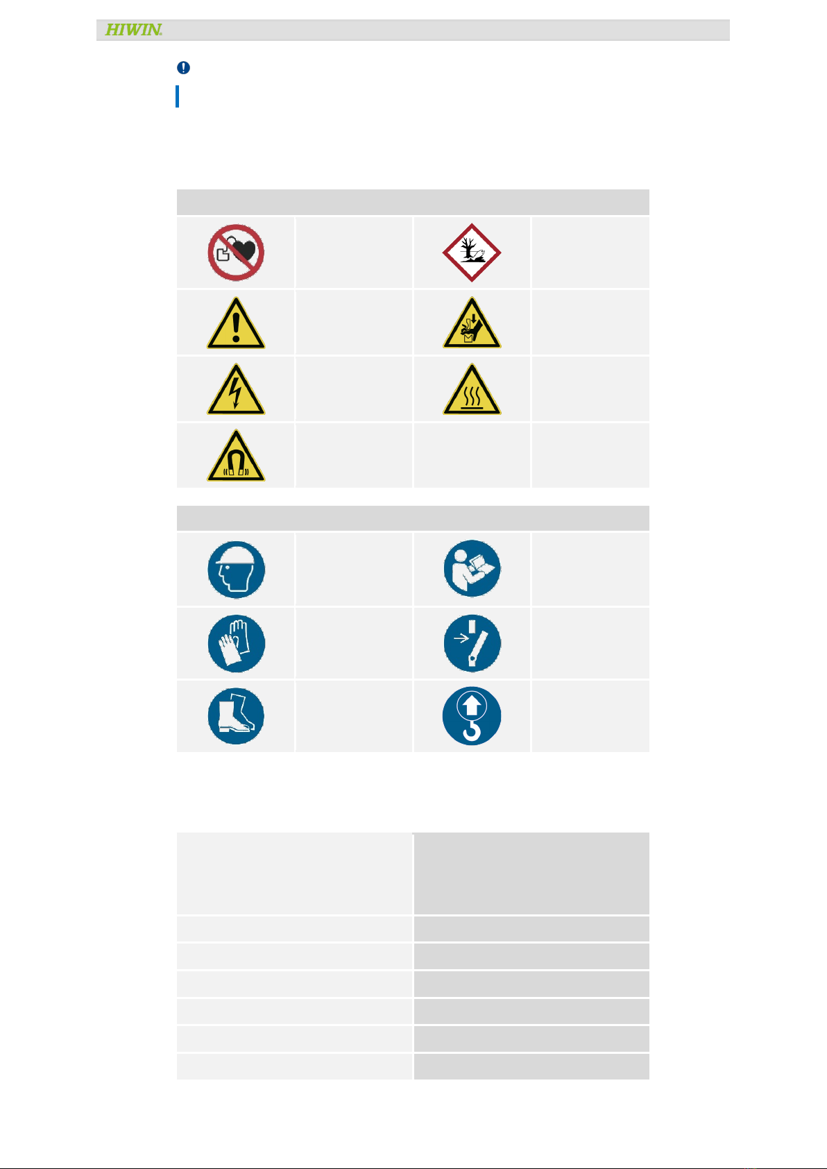
1.2 Depictions used in this user manual.............................................................................................................. 4
1.3 Manufacturer’s details ................................................................................................................................. 5
1.4 Product monitoring ...................................................................................................................................... 6
2Basic safety notices .................................................................................................................... 7
2.1 Intended use................................................................................................................................................ 7
2.2 Reasonably foreseeable misuse.................................................................................................................... 7
2.3 Conversions and modifications ..................................................................................................................... 7
2.4 Residual risks.............................................................................................................................................. 7
2.5 Personnel requirements ............................................................................................................................... 8
2.6 Protective equipment................................................................................................................................... 8
2.7 Labels on linear motor system...................................................................................................................... 9
3Description of the linear motor system..........................................................................................10
3.1 Order code..................................................................................................................................................10
3.2 Field of application .....................................................................................................................................11
3.3 Main components of the linear motor system ...............................................................................................12
3.4 Functional description.................................................................................................................................13
3.5 Linear motor-system...................................................................................................................................13
3.6 Linear motor ...............................................................................................................................................13
3.7 Positioning measurement system ................................................................................................................14
3.8 Limit switches (optional).............................................................................................................................15
3.9 Cable chain (optional) .................................................................................................................................15
4Transport and Installation ...........................................................................................................17
4.1 Delivery......................................................................................................................................................17
4.2 Transport to the installation site..................................................................................................................17
4.3 Requirements at the installation site ...........................................................................................................18
4.4 Storage ......................................................................................................................................................19
4.5 Unpacking and installing.............................................................................................................................19
5Assembly and connection............................................................................................................20
5.1 Assembling the linear motor system ............................................................................................................21
5.2 Assembling the moved load.........................................................................................................................22
5.3 Electrical connection...................................................................................................................................22
6Commissioning ..........................................................................................................................29
6.1 Switch on the linear motor system...............................................................................................................29
6.2 Programming..............................................................................................................................................30
7Maintenance and cleaning ...........................................................................................................31
7.1 Linear motor ...............................................................................................................................................33
7.2 Positioning measurement system ................................................................................................................33
7.3 Electromechanical components ...................................................................................................................33
7.4 Linear guideways ........................................................................................................................................33
8Troubleshooting.........................................................................................................................38
9Disposal....................................................................................................................................39
10 Declaration of Incorporation ........................................................................................................40

Contents
Linear motor axis LMSSA LMSSA-01-1-EN-2201-MA Seite 4von 44
1General information
1.1 About this user manual
1.1.1 Requirements
We assume that
operating staff are trained in the safe operation practices for linear motor systems and have read and
understood this user manual in full;
maintenance staff maintain and repair the linear motor systems in such a way that they pose no danger to
people, property or the environment.
1.1.2 Availability
This user manual must remain constantly available to all persons who work with or on the linear motor systems.
1.2 Depictions used in this user manual
1.2.1 Instructions
Instructions are indicated by triangular bullet points in the order in which they are to be carried out.
Example:
Position the linear motor system on the mounting holes.
Place the mounting bolts into the mounting holes and tighten in a spiral pattern to a torque of 10 Nm.
1.2.2 Lists
Lists are indicated by bullet points.
Example:
The linear motor systems must not be operated:
Outdoors
In potentially explosive atmospheres
1.2.3 Information
Information is to describe general information and recommendations.
Example:
Note:
Please contact HIWIN for special requests.
1.2.4 Depiction of safety notices
Safety notices are always indicated using a signal word and sometimes also a symbol for the specific risk (See
section 1.2.4). The following signal words and risk levels are used:
Danger!Imminent danger!
Non-compliance with the safety notices will result in serious injury or death!
Warning! Potentially dangerous situation!
Non-compliance with the safety notices runs the risk of serious injury or death!

Contents
Linear motor axis LMSSA LMSSA-01-1-EN-2201-MA Seite 5von 44
Attention!Potentially dangerous situation!
Non-compliance with the safety notices runs the risk of damage to property or environmental pollution!
1.2.5 Symbols used
The following symbols are used in this user manual and on the linear motor system:
Warning and prohibition signs
No access for people with
active implanted cardiac
devices.
Substance hazardous to the
environment!
Warning!
Warning of crushing of
hands!
Warning of electricity!
Warning of hot surface!
Warning of magnetic field!
Mandatory signs
Wear head protection!
Wear safety footwear!
Wear protective gloves!
Disconnect before carrying
out maintenance or repair.
Wear safety footwear!
Lifting point
1.3 Manufacturer’s details
Address
HIWIN GmbH
Brücklesbünd 1
77654 Offenburg
Germany
Phone
+49 (0) 781 932 78-0
Technical customer service
+49 (0) 781 / 9 32 78 - 77
Fax
+49 (0) 781 932 78-90
Technical customer service fax
+49 (0) 781 / 9 32 78 - 97
E-mail
support@hiwin.de
Website
www.hiwin.de

Contents
Linear motor axis LMSSA LMSSA-01-1-EN-2201-MA Seite 6von 44
1.4 Product monitoring
Please inform HIWIN, the manufacturer of the linear motor systems, of:
Accidents
Potential sources of danger in the linear motor systems
Anything in this user manual which is difficult to understand

Contents
Linear motor axis LMSSA LMSSA-01-1-EN-2201-MA Seite 7von 44
2Basic safety notices
Danger!Danger from strong magnetic fields!
Strong magnetic fields around linear motor systems pose a health risk to persons with implants (e.g. cardiac
pacemakers) that are affected by magnetic fields.
Persons with implants that are affected by magnetic fields should maintain a safe distance of at least 1 m
from linear motor systems.
Attention!Risk of physical damage to watches and magnetic storage media.
Strong magnetic forces may destroy watches and magnetisable data storage media near to the linear motor
system!
Do not bring watches or magnetisable data storage media into the vicinity (<300 mm) of the linear motor
systems!
2.1 Intended use
The linear motor system is a linear drive and guiding system for the precise positioning of fixed mounted loads,
e.g. system components within an automated system, in terms of time and location.
The LMSSA linear motor systems are designed for installation and operation in horizontal positions and therefore
do not feature parking brakes in their standard versions. In the case of vertical assembly, a parking brake,
weight compensation device or both must be retrofitted. The loads to be moved must either be mounted on to
the forcer or the base.
The linear axes can be mounted on top of one another to create multi-axis systems.
The specified linear motor systems may not be used outdoors or in hazardous areas where there is a risk of
explosions. All linear motor systems may only be used for the stated intended purpose.
The linear motor system must be operated within its specified performance limits (See Technical
Information and the Approval Drawing).
Observation of the user manual and compliance with the maintenance and repair regulations are
prerequisites for the intended use of the linear motor systems.
Any other use of the linear motor system shall be considered as contrary to the intended use.
Use only genuine spare parts from HIWIN.
2.2 Reasonably foreseeable misuse
The linear motor systems must not be operated:
Outdoors
In potentially explosive atmospheres
2.3 Conversions and modifications
Modifications of the linear motor systems are not permitted! Please contact HIWIN for special request.
2.4 Residual risks
Normal operation of the linear motor systems constitutes no residual risks.
Warnings about risks that may arise during maintenance and repair work are provided in the relevant sections.

Contents
Linear motor axis LMSSA LMSSA-01-1-EN-2201-MA Seite 8von 44
2.5 Personnel requirements
Only authorized persons may carry out work on the linear motor systems! They must be familiar with the safety
equipment and regulations before starting work (see following table).
Activity
Qualification
Normal operation Trained personnel
Cleaning Trained personnel
Maintenance Trained specialist personnel of the operator or manufacturer
Repairs Trained specialist personnel of the operator or manufacturer
2.6 Protective equipment
2.6.1 Personal protective equipment
Attention!Risk of noise.
The information below will enable the user of the machine to make a better evaluation of the hazard and risk.
–Equivalent A-weighted Sound pressure level according to EN ISO 3746: 70.5 dB (A)
–Uncertainty, K in decibels: 4.0 dB (A) according to EN ISO 4871
The emission levels are not necessarily safe working levels. Whilst there is a correlation between the
emission and exposure levels, this cannot be used reliably to determine whether or not further precautions
are required. Factors that influence the actual level of exposure of the work-force include the characteristics
of the work room, the other sources of noise, etc. i.e. the number of machines and other adjacent processes,
and the length of time for which an operator is exposed to the noise. Also the permissible exposure level can
vary from country to country.
Table 2.1: Personal protective equipment
Operating phase
Personal protective equipment
Normal operation When in the vicinity of the linear motor systems, the following personal protective
equipment is required:
Safety shoes
Protective helmet
Protective gloves
Cleaning When cleaning the linear motor systems, the following personal protective equipment is
required:
Safety shoes
Protective helmet
Protective gloves
Maintenance and repairs When carrying out maintenance and repairs, the following personal protective equipment is
required:
Safety shoes
Protective helmet
Protective gloves
2.6.2 Protective equipment on the linear motor system
Linear motor systems are fitted with position dampers.
After every traverse, these position dampers must be tested at the end positions and, if necessary, replaced.
The machine may not be operated without position dampers or when they are damaged!

Contents
Linear motor axis LMSSA LMSSA-01-1-EN-2201-MA Seite 9von 44
2.7 Labels on linear motor system
Fig. 2.1: Warning symbols and type plate – here for a LMSSA linear motor system
Table 2.2: Waning symbols
Pictogramm
Type and source of danger
Protective measures
Danger from movements! Keep out of the machine’s area of
movements! Prevent unauthorized
access to the danger area!
Danger from strong magnetic fields! Persons whose health may be
endangered by strong magnetic fields
must keep a safe distance (1 m) from
the linear motor system!

Contents
Linear motor axis LMSSA LMSSA-01-1-EN-2201-MA Seite 10 von 44
3Description of the linear motor system
3.1 Order code
Number
1
2
3
4
5
6
7
Order code
LMSSA
13
S
100
1
800
G
1
LMSSA
Linear motor axis
2
13
Width [mm]:
08: 80
10: 100
13: 135
18: 185
20: 206
3
S
Motor type:
S: Ironcore
C: Ironless
4
100
Rated force level 1):
050, 100, 200, 300, 500, 700
5
1
Number of forcers:
1: Single forcer
2: Dual forcers
6
800
Stroke [mm]:
100 ~ 2.700
(Available in 50 mm increment up to 1.300 mm and 100 mm increments up to 2.700 mm)
7
G
Encoder type:
A: Analog optical
D: Analog magnetic
E: Digital 1 µm resolution magnetic encorder
G: Digital 1 µm resolution optical encorder
K: Digital 0,1 µm resolution optical encorder
H: Hall encoder (Analog)
P: Absolut optical encoder 0,5 µm (BiSS-C)

Contents
Linear motor axis LMSSA LMSSA-01-1-EN-2201-MA Seite 11 von 44
Number
8
9
10
11
12
13
Order code
5.3
A
S
S
A
0000
8
5.3
Cable length 2), 3), 5):
3.3: Power: 3 m/Encoder: 3 m
5.3: Power: 5 m/Encoder: 3 m
7.3: Power: 7 m/Encoder: 3 m
9
A
Limit switch:
A: NPN.NC
B: PNP.NC
10
S
Cover:
S: S cover
M: M cover
P: P cover (Coming soon)
11
S
Color:
S: Aluminium color
B: Black
12
A
Voltage:
A: Standard
B: High voltage
13
0000
Costum code:
0000: Standard
1) Width is defined by rated force level. Please refer Product Dimension and Specification on p.8.
2) Cable length can be customized. Please refer to p. 11 for standard cable length.
3) Standard encoder cable terminates with D-sub connectors. Extension cable is required when connecting to
HIWIN drive.
4) Encoder extension cable is sold separately (see p.58).
5) The length of cable is measured from the motor/encoder. Tor the length from the forcer plate will be 0,5 m
shortet, eg. Cable length 3 m 2,5 m; 5 m 4,5 m; 7 m 6,5 m.
3.2 Field of application
The linear motor system is used for traversing and (linear) movement of fixed mounted loads on the forcer
housing. The model can be mounted and operated horizontally.

Contents
Linear motor axis LMSSA LMSSA-01-1-EN-2201-MA Seite 12 von 44
3.3 Main components of the linear motor system
Fig. 3.1: Main components of the linear motor system – here for a LMSSA linear motor system
Table 3.1: Main components of the linear motor system
Pos.
Components
Pos.
Components
1
Cover
8
Linear guideway
2
Forcer (primary part)
9
Encoder with mounting bracket
3
Reference and limit switches with mounting bracket
10
Linear guideway block
4
End plate
11
Scale
5
Stator (secondary part of the linear motor)
12
Position damper
6
Base
13
Forcer housing
7
Cover

Contents
Linear motor axis LMSSA LMSSA-01-1-EN-2201-MA Seite 13 von 44
3.4 Functional description
Fig. 3.2: Principle of the linear motor system
Table 3.2: Components and functionality
Pos.
Function
1
Energy supply (standard version or customer-specific version)
2
Positive (+) direction of motion. This is defined via the position of the reference switch.
3
Motor cables, positioning measurement system, limit switches.
4
Drive D1
Drive D1-N (with functional safety, suggested for users from Europe)
Drive D2T-LM
Drive E1 (with functional safety, suggested for users from Europe)
3.5 Linear motor-system
A linear motor system comprises a base with integrated linear guideways. These both absorb the forces exerted
by the weights, accelerations, and processes and provide precise guiding for the forcer housing. The axis is
driven by linear motors.
3.6 Linear motor
A linear motor consists of two components, the forcer (primary part) with coils and the stator (secondary part)
with permanent magnets. The coils carrying alternating current generate a magnetic field that changes over time
and interacts with the steady magnetic field of the stator. The resulting force is used to generate linear motion.
The linear motor components are supplied as separate parts.
Table 3.3: Linear motor selection
Order code
Motor type
Continuous force [N]
Peak force [N]
08S050
LMSA01 52 145
08S100
LMSA02 104 290
10S100
LMSA11 103 289
13S100
18S100

Contents
Linear motor axis LMSSA LMSSA-01-1-EN-2201-MA Seite 14 von 44
Order code
Motor type
Continuous force [N]
Peak force [N]
10S200
LMSA12 205 579
13S200
18S200
13S300
LMSA13 308 868
18S300
18C100
LMC-EFC2 75 300
18C200
LMC-EFC4 150 600
20S300
LMSA22 362 1.023
20S500
LMSA23 544 1.535
20S700
LMSA24 725 2.048
20C100
LMCB5 91 364
20C200
LMCB8 145 580
3.7 Positioning measurement system
Attention! Damage caused by scratching!
The measuring scale of the optical measuring system may be damaged by improper handling.
Handle the measuring scale with care!
Attention! Damage to the magnetic positioning measurement system!
Strong magnetic fields and vibrations can damage the magnetic positioning measurement system.
Protect the magnetic positioning measurement system against strong magnetic fields!
Protect the magnetic positioning measurement system against strong vibrations!
The distance travelled is measured by a high-resolution positioning measurement system that is mounted on the
base. Depending on its type, the linear motor system features an optical or a magnetic positioning measurement
system. The installed positioning measurement system is fully cabled and is connected to the controller via a
separate connector (See Technical Information and Approval Drawing).
Table 3.4: Positioning measurement system selection
Order code
Encoder type
Resolution [μm]
Interface
Scale type
A
Q4BCA30L00T 0,1 Incremental 1 Vpp (analogue) RTLC40-S
D
PM-B-03-3A-T-10 1,0 Incremental 1 Vpp (analogue) SB-20
E
PM-B-03-3D-T-10 1,0 Incremental TTL (digital) SB-20
G
Q4BCX30D20A 1,0 Incremental TTL (digital) RTLC40-S
K
Q4BCY30D20A 0,1 Incremental TTL (digital) RTLC40-S
H
LMAESA-A-30-3 2,0 Incremental 1 Vpp (analogue) stator
P
EL26BBB500F30A 0,5 Absolute, 26-bit BiSS-C RTLA50-S

Contents
Linear motor axis LMSSA LMSSA-01-1-EN-2201-MA Seite 15 von 44
3.8 Limit switches (optional)
Depending on the type, a few optical or inductive switches generate a signal to the controller upon reaching the
end of the travel distance. The limit switches are supplied pre-wired and operational.
Abb. 3.1: Pin assignment (standard)
3.9 Cable chain (optional)
Table 3.5: Information of motor cable
Order code
Outer diameter [mm]
Bend radius (moved)
Bend radius (fixed)
08S050
9,2 69 37
08S100
10S100
10S200
13S100
13S200
13S300
18S100
18S200
18S300
18C100
6,2 45 24
18C200
20S300
9,2 69 37
20S500
20S700
20C100
7,5 45 24
20C200
7,5 45 24

Contents
Linear motor axis LMSSA LMSSA-01-1-EN-2201-MA Seite 16 von 44
Table 3.6: Information of motor cable
Order code
Outer diameter [mm]
Bend radius (moved)
Bend radius (fixed)
A
4,25 30 10
D
5 38 20
E
5 38 20
G
4,25 30 10
K
4,25 30 10
H
5 38 20
P
4,7 20 10

Contents
Linear motor axis LMSSA LMSSA-01-1-EN-2201-MA Seite 17 von 44
4Transport and Installation
4.1 Delivery
4.1.1 Delivery state
The linear motor systems are supplied fully assembled, function tested and ready for connection. To prevent
damage arising during transport, the linear motor systems are provided with transportation safety devices and
shipping devices.
4.1.2 Scope of delivery
For the scope of delivery, please see the contractual documentation.
4.2 Transport to the installation site
Danger!Danger from strong magnetic fields!
Strong magnetic fields around linear motor system pose a health risk to persons with implants (e.g. cardiac
pacemakers) that are affected by magnetic fields.
Persons with implants that are affected by magnetic fields should maintain a safe distance of at least 1 m
from linear motor system.
Warning! Risk of crushing from forcer housing!
Danger of injury from crushing and damage to the linear motor system caused by movement of the forcer
housing due to gravity, as it does not feature brakes in its standard version.
Ensure that each transportation safety devices is well fixed before transportation. In most cases, the
devices are made in red.
Warning! Danger from heavy loads!
Lifting heavy loads may damage your health.
For system’s weight over 20 kg, use a hoist of an appropriate size when positioning heavy loads!
Observe applicable occupational health and safety regulations when handling suspended loads!
Attention!Risk of physical damage to watches and magnetic storage media.
Strong magnetic forces may destroy watches and magnetisable data storage media near to the linear motor
system!
Do not bring watches or magnetisable data storage media into the vicinity (<300 mm) of the linear motor
system!
Attention!Damage of the linear motor system!
The linear motor system may be damaged by mechanical loading.
No heavy load on the cover!
Lift the linear motor system using the shipping devices (Fig. 4.2)!
For longer linear motor system, provide additional protection of the center section.
Ensure that the linear motor system does not bend as this could permanently damage accuracy.
During transport, do not transport any additional loads on the linear motor system!
Secure the linear motor system and components against tilting!

Contents
Linear motor axis LMSSA LMSSA-01-1-EN-2201-MA Seite 18 von 44
Note:
Electrical equipment is designed to withstand to protect against the effects of transportation, and storage
temperature within a range of -25 °C to +55 °C and for short periods not exceeding 24h at up to +70 °C.
Steps to transport the linear motor system:
Disconnect power supply.
Disconnect stage cables.
Remove the payload.
To transport the linear axis, hoist it at the points designated A and B (Fig. 4.1).
Ensure even load distribution while lifting.
Fig. 4.1: Hoisting and transporting – here for a linear motor system
Fig. 4.2: Hoisting and transporting – Incorrect position of the supporting points
4.3 Requirements at the installation site
4.3.1 Ambient conditions
Area of use
For indoor use only
Temperature
0 °C bis 50 °C
Humidity
< 80% RH (non-condensing)
Altitude
< 1000 m
Installation site
Flat, dry, vibration-free
Protection class
IP50 and no interference from corrosive solvent or strong magnetic
Grounding
Plant power grounding line conforms to international requirements
Avoid exposing to direct sunlight or hear rays.
Away from electric magnetic interference source sites, such as welding, discharge machine.
A
B

Contents
Linear motor axis LMSSA LMSSA-01-1-EN-2201-MA Seite 19 von 44
4.3.2 Safety equipment to be provided by the operator
Possible safety equipment/measures:
Personal protective equipment in accordance with regional regulations
Zero-contact protective equipment
Mechanical protective equipment
4.4 Storage
Danger!Danger from strong magnetic fields!
Strong magnetic fields around linear motor systems pose a health risk to persons with implants (e.g. cardiac
pacemakers) that are affected by magnetic fields.
Persons with implants that are affected by magnetic fields should maintain a safe distance of at least 1 m
from linear motor systems.
Store the linear motor system in its transport packaging.
Only store the linear motor system in dry, frost-free areas with a corrosion-free atmosphere.
Clean and protect used linear motor system before storage.
When storing the linear motor system, attach signs warning of magnetic fields.
4.5 Unpacking and installing
Attention!Damage of attachments!
Attachments may be damaged by mechanical loading.
Secure and manoeuvre the linear motor system using the suspension points provided!
Note:
The linear motor system may only be installed and operated indoors.
Note:
The linear motor system is designed exclusively for horizontal installation. During installation, the linear motor
system must not exceed an angle of 1° as it does not feature a parking brake.
Steps to unpack and install the linear motor system:
Remove protective film.
Carefully transport the linear motor system on the shipping devices provided to the specified installation
site.
Ensure that the maintenance points are easily accessible.
Dispose of packaging in an environmentally friendly way.

Contents
Linear motor axis LMSSA LMSSA-01-1-EN-2201-MA Seite 20 von 44
5Assembly and connection
Danger!Danger from electrical voltage!
Before and during assembly, disassembly and repair work, dangerous currents may flow.
Work may only be carried out by a qualified electrician and with the power supply disconnected!
Before carrying out work on the linear motor system, disconnect the power supply and protect it from being
switched back on!
Danger!Risk of crushing from strong forces of attraction!
There is a risk of crushing from the strong forces of attraction emitted by the stators, as they are assembled
with opposing polarity!
Assemble the stators carefully!
Do not place fingers or objects between the stators!
Warning! Risk of crushing from forcer housing!
Danger of injury from crushing and damage to the linear motor system caused by movement of the forcer
housing due to gravity, as it does not feature brakes in its standard version.
Ensure that the linear motor system does not exceed 1° horizontal deviation!
Warning! Risk of crushing from the forcer!
Danger of injury from crushing and damage to the forcer through uncontrolled movements during assembly.
Ensure that the forcer is locked in place during assembly using transportation safety devices!
Warning! Risk of crushing from strong forces of attraction!
Danger of injury from crushing and damage to the forcer or stator caused by very strong forces of attraction.
Ensure that the forcer only comes close to the stator when the linear guideways can absorb the forces!
Warning! Danger from heavy loads!
Lifting heavy loads may damage your health.
Use a hoist of an appropriate size when positioning heavy loads which are over 20 kg!
Observe applicable occupational health and safety regulations when handling suspended loads!
To transport the linear axis, hoist it at the points designated A and B (see Section 4.2)!
Attention!Damage of the linear motor system!
The linear motor system may be damaged by mechanical loading.
No heavy load on the cover!
No moving the forcer housing!
Note:
The mounting surface must have a flatness of 0.03 mm over 300 mm.
Note:
The linear motor system may only be assembled by specialist personnel.
This manual suits for next models
1
Table of contents
Other Hiwin Industrial Equipment manuals
Popular Industrial Equipment manuals by other brands

Zimmer
Zimmer WWR Series Installation and operating instructions

BONFIGLIOLI
BONFIGLIOLI HDP Series manual

Vestil
Vestil CB-S-2S quick start guide

Blue Ox
Blue Ox BedSaver BXR5000 Operator and installation manual

ABB
ABB Unifix AD Instruction handbook

Regal Rexnord
Regal Rexnord Thomas XTSR Series Installation and maintenance manual