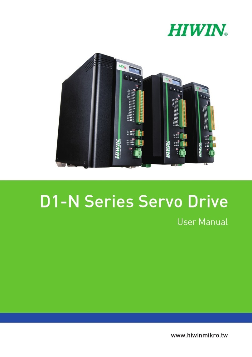
Hiwin E1 Series User manual

www.hiwinmikro.tw
User Manual
E1 Series Servo Drive
MD09UE01-1910_V1.4

E1 Series Servo Drive User Manual Revision History
Revision History
The version of the manual is also indicated on the bottom of the front cover.
Release Date Version Applicable Product Revision Contents
October 9th, 2019 1.4 E1 series servo drive
1. Revise Approvals.
2. Change the names of sections 2.2.3 and 7.4.2.
3. Revise section 2.1.2 Model explanation.
4. Revise section 3.3.2 Pin definition.
5. Revise section 3.5 ESC specifications.
6. Add section 3.5.1 ESC hardware.
7. Add section 3.5.2 ESC cables.
8. Revise section 4.3 Basic specification.
9. Revise section 4.4 Selecting no-fuse breaker
(NFB).
10. Revise section 5.6.2 Wiring for STO safety
function.
11. Revise section 6.12.4 Encoder delay time.
12. Revise section 6.14 Over temperature
protection.
13. Revise section 7.4.2 Inspection procedure for
customized servo motor (AC)/linear motor
(LM)/direct drive motor (DM).
14. Revise section 7.5 Detection for electrical
angle.
15. Revise section 8.4.4 Positioning completion
output (COIN) signal.
16. Revise section 8.6.2 Setting encoder pulse
output.
17. Revise section 8.11.1 Setting internal homing.
18. Revise section 8.13 Setting position trigger
function.
19. Revise section 8.16.6 Related settings of unit
conversion.
20. Revise section 10.2.3 Setting alarm value for
overflow position deviation.
21. Revise section 10.5.1 Setting current gain level.
22. Revise section 10.6.1 Adjusting servo gains.
23. Revise section 10.6.2 Gain parameters.
24. Revise section 10.6.3 Torque command filter.
25. Revise section 11.3.2 Scope and data
collection.
26. Revise section 12.6 Connecting to safety
module.
27. Revise section 13.2.1 Alarm list.
28. Revise section 13.2.2 Causes and corrective
actions for alrams.
29. Revise section 13.3.1 Warning list.
30. Revise section 13.3.2 Causes and corrective
actions for warnings.
31. Revise section 15.2 List of parameters.
32. Revise section 16.1.2 Encoder extension cable
for servo motor.
33. Revise section 16.1.4 ESC encoder extension
cable.
MD09UE01-1910_V1.4
Version
Release date

E1 Series Servo Drive User Manual Revision History
Release Date Version Applicable Product Revision Contents
34. Revise section 16.2.3 Connector specification.
35. Support firmware version 2.2.7.
August 30th, 2019 1.3 E1 series servo drive
1. Revise Approvals.
2. Revise section 2.1.2 Model explanation.
3. Revise section 2.2.1 Servo motor (AC).
4. Revise section 2.2.2 Linear motor (LM).
5. Revise section 2.2.3 Direct drive motor (DM).
6. Revise section 2.3 Selecting regenerative
resistor.
7. Revise section 3.1 Model explanation of
Excellent Smart Cube (ESC).
8. Add section 3.1.1 Nameplate.
9. Add section 3.1.2 Model explanation.
10. Revise section 3.3.1 Terminal symbols and
terminal names.
11. Revise section 3.3.2 Pin definition.
12. Revise section 3.4 Status indicator.
13. Add section 3.5 Basic specification.
14. Revise section 4.1.1 E1 series servo drive
(Standard)
15. Revise section 4.1.2 E1 series servo drive
(Fieldbus)
16. Revise section 4.3 Basic specification.
17. Revise section 4.4 Selecting no-fuse breaker
(NFB).
18. Revise section 5.2 Wiring diagram for control
mode.
19. Revise section 5.3.1 Terminal symbols and
terminal names.
20. Revise section 5.3.5 Wiring for regenerative
resistor.
21. Revise section 5.4.1 Terminal symbols and
terminal names.
22. Revise section 5.5.1 Control signal connector.
23. Revise section 5.5.3 Wirings for digital inputs
and digital outputs.
24. Revise section 5.6.2 Wiring for STO safety
function.
25. Revise section 6.10.2 Detection timing for
overload alarm (AL.720).
26. Revise section 6.10.3 Maximum duration for
motor peak current.
27. Revise section 6.14 Over temperature
protection.
28. Revise section 7.6.1 JOG.
29. Revise section 8.13 Setting position trigger
function.
30. Revise section 13.5.2 Replacement standard.
31. Revise section 15.2 List of parameters.
32. Revise section 16.1.2 Encoder extension cable
for servo motor.
33. Revise section 16.1.3 Encoder extension cable
for linear motor.
34. Revise section 16.1.4 ESC encoder extension
cable.
35. Revise section 16.1.5 Control signal cable.
36. Revise section 16.1.6 Communication cable.
37. Revise section 16.2.1 Accessory kit.
38. Revise section 16.2.2 Power supply filter.
39. Revise section 16.2.3 Connector specification.
June 14th, 2019 1.2 E1 series servo drive
1. Revise table 3.1.1 in section 3.1.
2. Revise chapter 16 Appendix.
3. Change figures 5.4.3.2 and 6.10.2.1.

E1 Series Servo Drive User Manual Revision History
Release Date Version Applicable Product Revision Contents
March 29th, 2019 1.1 E1 series servo drive
1. Add new parameters and descriptions.
2. Add chapter 16 Appendix.
February 27th, 2019 1.0 E1 series servo drive First edition

E1 Series Servo Drive User Manual Preface
Preface
This manual aims to assist users to operate E1 series servo drive. The contents in this manual, including
manual preface, evaluation of mechanism design, precautions for electrical planning, software setting,
operation and troubleshooting, are arranged in accordance with the procedure of configuring a machine.
Carefully read through this manual to correctly operate E1 series servo drive.

E1 Series Servo Drive User Manual Approvals
Approvals
Servo Drive Model
Approvals
EU Directives UL Approval
EMC Directives
IEC / EN 61800-3: 2004/A1:
2012 (Category C3)
Low-voltage Directives
IEC / EN 61800-5-1:2007
(PD2, OVC III)
UL 61800-5-1
CSA C22.2 No. 274-17
ED1□-□□-04□□-□□
ED1□-□□-10□□-□□
ED1□-□□-20□□-□□ N/A
Note:
EN: Europischen Normen = European standard
Excellent Smart
Cube (ESC) Model
Item
EU Directives Federal Communications Commission
EMC Directives
IEC / EN 61800-3:
2004/A1: 2012
(Category C3)
Low-voltage
Directives
IEC / EN
61800-5-1:2007
(PD2 ,OVC III)
Conducted Emission
ANSI C63.4-2014,
FCC Part 15 Subpart
B, KDB174176
CISPR PUB. 22
Radiated Emission
ANSI C63.4-2014,
FCC Part 15 Subpart
B, KDB174176
CISPR PUB. 22
ESC-□□-□□□

E1 Series Servo Drive User Manual General Precautions
General Precautions
Before using the product, please carefully read through this manual. HIWIN Mikrosystem (HIWIN) is not
responsible for any damage, accident or injury caused by failure in following the installation instructions
and operating instructions stated in this manual.
Do not disassemble or modify the product. The design of the product has been verified by structural
calculation, computer simulation and actual testing. HIWIN is not responsible for any damage,
accident or injury caused by disassembly or modification done by users.
Before installing or using the product, ensure there is no damage on its appearance. If any damage
is found after inspection, please contact HIWIN or local distributors.
Carefully read through the specification noted on the product label or technical document. Install the
product according to its specification and installation instructions stated in this manual.
Ensure the product is used with the power supply specified on the product label or in the product
requirement. HIWIN is not responsible for any damage, accident or injury caused by using incorrect
power supply.
Ensure the product is used with the rated load. HIWIN is not responsible for any damage, accident or
injury caused by improper usage.
Do not subject the product to shock. HIWIN is not responsible for any damage, accident or injury
caused by improper usage.
If an error occurs in the servo drive, please refer to chapter 13 and follow the instructions for
troubleshooting. After the error is cleared, power on the servo drive again.
Do not repair the product by yourselves when it malfunctions. The product can only be repaired by
qualified technician from HIWIN.
HIWIN offers 1 year warranty for the product. The warranty does not cover damage caused by improper
usage (Refer to the precautions and instructions stated in this manual.) or natural disaster.
CAUTION
The maximum ambient temperature must be below 45 oC.
The product can only be installed in an environment with pollution degree not exceeding 2.
The control power input must be: 220 VAC, 1 A and level 2.
The rated voltage input is 240 VAC. Short-circuit current must be below 5000 A.
Before inspection, please turn off the power and wait for at least 15 minutes. To avoid electric shock, ensure the residual
voltage between P and N terminals has dropped to 50 VDC or lower by using multimeter.
The short circuit protection for internal circuits does not support branch circuit protection. Branch circuit protection must be
implemented in accordance with the National Electrical Code and any additional local codes. Refer to the table below for
the suggested fuses used in both the main power input (L1, L2, L3) and control power input (L1C, L2C) of the servo drive.
Servo Drive Model
Suggested Model
BCP Fuse Class
BCP Fuse Rating
ED1□-□□-01□□-□□
Littelfuse / JLLN002.T
Class T
300V, 2A
ED1□-□□-04□□-□□
Littelfuse / JLLN006.T
Class T
300V, 6A
ED1□-□□-10□□-□□ Littelfuse / JLLN015.T Class T 300V, 15A
The servo drive is suitable for use in a circuit capable of delivering not more than 5000 rms symmetrical amperes and 240
volts maximum.
The level of motor overload protection is the percentage of full-load current. (120% of full-load current)
The servo drive does not provide motor over-temperature protection.
Use copper conductors of rated temperature 60/75°C.

E1 Series Servo Drive User Manual Safety Precautions
Safety Precautions
Carefully read through this manual before installation, transportation, maintenance and examination.
Ensure the product is correctly used.
Carefully read through electromagnetic (EM) information, safety information and related precautions
before using the product.
Safety precautions in this manual are classified into “Warning”, “Attention”, “Prohibited” and
“Required”.
Signal Word Description
If the precaution is not observed, it is likely to cause property loss, serious
injury or death.
The precaution must be observed.
Prohibited activity
Mandatory activity
DANGER
Ensure the servo drive is correctly grounded. Use PE bar as reference potential in control box.
Perform low-ohmic grounding for safety reason.
Do not remove the motor power cable from the servo drive when it is still power-on, or there is a risk of electric
shock or damage to contact.
Do not touch the live parts (contacts or bolts) within 15 minutes after disconnecting the servo drive from its
power supply. For safety reason, we suggest measuring the voltage in the intermediate circuit and wait until it
drops to 50 VDC.
Operation
Do not touch the terminals or internal parts of the product when power on, or it may
cause electric shock.
Do not touch the terminals and internal parts of the product within ten minutes after
power off, or the residual voltage may cause electric shock.
Do not modify wiring when power on, or it may cause electric shock.
Do not damage, apply excessive force to, place heavy object on the cables. Or put the
cables between two objects. Otherwise, it may cause electric shock or fire.
Do not use the product in location which is subject to humidity, corrosive materials,
flammable gas or flammable materials.

E1 Series Servo Drive User Manual Safety Precautions
Storage
Do not store the product in location which is subject to water, water drop, harmful gas,
harmful liquid or direct sunlight.
Transportation
Carefully move the product to avoid damage.
Do not apply excessive force to the product.
Do not stack the products to avoid collapse.
Installation site
Do not install the product in location with high ambient temperature and high humidity
or location which is subject to dust, iron powder or cutting powder.
Install the product in location with ambient temperature stated in this manual. Use
cooling fan if the ambient temperature is too high.
Do not install the product in location which is subject to direct sunlight.
The product is not drip-proof or waterproof, so do not install or operate the product
outdoor or in location which is subject to water or liquid.
Install the product in location with less vibration.
Motor generates heat while running for a period of time. Use cooling fan or disable the
motor when it is not in use, so the ambient temperature will not exceed its specification.
Installation
Do not place heavy object on the product, or it may cause injury.
Prevent any foreign object from entering the product, or it may cause fire.
Install the product in the specified orientation, or it may cause fire.
Avoid strong shock to the product, or it may cause malfunction or injury.
While installing the product, take its weight into consideration. Improper installation
may cause damage to the product.
Install the product on noncombustible object, such as metal to avoid fire.
Wiring
Ensure wiring is correctly performed. Otherwise, it may lead to product malfunction or
burn-out. There could be a risk of injury or fire.
Operation and transportation
Use power supply specified in product specification, or it may cause injury or fire.
The product may suddenly start to operate after power supply recovers. Please do not
get too close to the product.
Set external wiring for emergency stop to stop the motor at any time.
Maintenance
Do not disassemble or modify the product.
If the product malfunctions, do not repair the product by yourselves, please contact
HIWIN for repair.

E1 Series Servo Drive User Manual Safety Precautions
(This page is intentionally left blank.)

E1 Series Servo Drive User Manual Chapter Overview
Chapter Overview
Chapter
Title
Contents
1 E1 series servo motor This chapter introduces servo motor models.
2 E1 series servo drive This chapter introduces servo drive models and regenerative
resistor selection.
3 Excellent Smart Cube (ESC) This chapter provides model explanation of Excellent Smart
Cube (ESC).
4 Specification This chapter provides specification, dimensions and
installation instructions of the servo drive.
5 Electrical planning
This chapter provides wiring precautions and connector
introduction.
6 Basic function settings before
operation
This chapter describes basic functions which need to be set
before operation.
7 Software settings and trial
operation
This chapter describes how to do servo drive settings via
Thunder.
8 Application function
This chapter provides introduction of general-purpose digital
inputs, general-purpose digital outputs, control mode settings
and full-closed loop function.
9 Trial operation when
connected to controller
This chapter describes parameters which need to be set
when connected to controller.
10 Tuning This chapter describes servo tuning tools.
11 Monitoring This chapter describes servo drive status, I/O status and
physical quantity monitoring.
12 Safety function This chapter describes the supported safety function.
13
Troubleshooting and
maintenance
This chapter describes servo drive alarms and
troubleshooting.
14 Panel operation This chapter describes functions and operation of the servo
drive panel.
15 Parameters This chapter provides function parameters and parameter
numbers.
16 Appendix
This chapter provides the required accessories for servo
drive setup.

E1 Series Servo Drive User Manual Table Of Contents
Table of Contents
1. E1 series servo motor ················································································································1-1
Model explanation of servo motor (AC)·····················································································1-2
2. E1 series servo drive ·················································································································2-1
2.1 Model explanation of servo drive·····························································································2-2
2.1.1 Nameplate ··················································································································2-2
2.1.2 Model explanation·········································································································2-2
2.2 Servo drive and servo motor combination ·················································································2-3
2.2.1 Servo motor (AC)··········································································································2-3
2.2.2 Linear motor (LM) ·········································································································2-4
2.2.3 Direct drive motor (DM) ··································································································2-5
2.2.4 Motor current and servo drive current ················································································2-5
2.3 Selecting regenerative resistor ·······························································································2-6
3. Excellent Smart Cube (ESC) ·······································································································3-1
3.1 Model explanation of Excellent Smart Cube (ESC)······································································3-2
3.1.1 Nameplate ··················································································································3-2
3.1.2 Model explanation·········································································································3-2
3.2 Dimensions of Excellent Smart Cube (ESC) ··············································································3-3
3.3 Terminals of Excellent Smart Cube (ESC)·················································································3-4
3.3.1 Terminal symbols and terminal names···············································································3-4
3.3.2 Pin definition················································································································3-4
3.4 Status indicator ···················································································································3-6
3.5 ESC specifications···············································································································3-7
3.5.1 ESC hardware··············································································································3-7
3.5.2 ESC cables ·················································································································3-8
4. Specification ····························································································································4-1
4.1 Dimensions of E1 series servo drive ························································································4-2
4.1.1 E1 series servo drive (Standard) ······················································································4-2
4.1.2 E1 series servo drive (Fieldbus) ·······················································································4-5
4.2 Installation ·························································································································4-8
4.3 Basic specification ···············································································································4-9
4.4 Selecting no-fuse breaker (NFB) ··························································································· 4-12
5. Electrical planning·····················································································································5-1
5.1 Wiring precautions ···············································································································5-2
5.1.1 General precautions ······································································································5-2
5.1.2 Countermeasures against interference ··············································································5-4
5.1.3 Grounding ················································································································· 5-10
5.2 Wiring diagram for control mode ··························································································· 5-12
5.3 Wiring for power supply (CN1)······························································································ 5-15
5.3.1 Terminal symbols and terminal names············································································· 5-15
5.3.2 Wiring for main circuit connector ···················································································· 5-16
5.3.3 Power-on sequence ···································································································· 5-16
5.3.4 Wiring diagram for power supply ···················································································· 5-18
5.3.5 Wiring for regenerative resistor ······················································································ 5-21
5.3.6 Wiring for DC reactor ··································································································· 5-23
5.4 Wiring for servo motor ········································································································ 5-23
5.4.1 Terminal symbols and terminal names············································································· 5-23
5.4.2 Motor power connector (CN2)························································································ 5-24
5.4.3 Encoder connector (CN7) ····························································································· 5-24
5.4.4 Wiring for brake ·········································································································· 5-25
5.5 Control signals (CN6) ········································································································· 5-26
5.5.1 Control signal connector······························································································· 5-26
5.5.2 Wiring example of control mode ····················································································· 5-29
5.5.3 Wirings for digital inputs and digital outputs ······································································ 5-31
5.6 STO connector (CN4)········································································································· 5-34
5.6.1 Pin definition of STO connector······················································································ 5-34
5.6.2 Wiring for STO safety function ······················································································· 5-35

E1 Series Servo Drive User Manual Table Of Contents
5.7 Other connectors··············································································································· 5-36
5.7.1 Connector for PC communication (CN3) ·········································································· 5-36
5.7.2 Connector for Fieldbus communication (CN9) ··································································· 5-36
6. Basic function settings before operation ························································································6-1
6.1 Parameters ························································································································6-2
6.1.1 Parameter definition ······································································································6-2
6.1.2 Parameter list ··············································································································6-3
6.1.3 Parameter setting ·········································································································6-5
6.1.4 Parameter initialization···································································································6-5
6.2 Control modes ····················································································································6-7
6.3 Setting main circuit power supply ····························································································6-8
6.3.1 Setting single-phase/three-phase AC power input ································································6-8
6.4 Automatic motor identification ································································································6-8
6.5 Function and setting of servo on input (S-ON) signal ···································································6-9
6.5.1 Function of servo on input (S-ON) signal············································································6-9
6.5.2 Setting S-ON signal to be always on ·················································································6-9
6.6 Setting the moving direction of motor ····················································································· 6-10
6.7 Overtravel function············································································································· 6-11
6.7.1 Overtravel signals ······································································································· 6-12
6.7.2 Enabling/disabling overtravel function·············································································· 6-12
6.7.3 Motor stopping method for overtravel ·············································································· 6-12
6.7.4 Overtravel warning ······································································································ 6-14
6.8 Brake······························································································································ 6-15
6.8.1 Brake operating sequence ···························································································· 6-16
6.8.2 Brake control output (BK) signal ····················································································· 6-16
6.8.3 Output timing of BK signal when motor stops ···································································· 6-17
6.8.4 Output timing of BK signal when motor is operating ···························································· 6-18
6.9 Motor stopping methods for servo off and alarm ······································································· 6-20
6.9.1 Motor stopping method when servo off ············································································ 6-20
6.9.2 Motor stopping methods for alarm ·················································································· 6-21
6.10 Detection for motor overload ······························································································ 6-22
6.10.1 Detection timing for overload warning (AL.910) ································································ 6-23
6.10.2 Detection timing for overload alarm (AL.720) ··································································· 6-23
6.10.3 Maximum duration for motor peak current······································································· 6-24
6.11 Electronic gear ratio ········································································································· 6-25
6.11.1 Introduction to electronic gear ratio ··············································································· 6-25
6.11.2 Setting electronic gear ratio ························································································· 6-26
6.12 Setting encoder ··············································································································· 6-28
6.12.1 Precautions for initialization ························································································· 6-28
6.12.2 Tool ······················································································································· 6-29
6.12.3 Parameter settings for encoder ···················································································· 6-29
6.12.4 Encoder delay time···································································································· 6-30
6.13 Setting regenerative resistor······························································································· 6-30
6.14 Over temperature protection······························································································· 6-31
7. Software settings and trial operation ·····························································································7-1
7.1 Trial operation procedure ······································································································7-2
7.2 Software installation and connection ························································································7-3
7.3 Configuration Wizard············································································································7-4
7.4 Inspection before trial operation ······························································································7-5
7.4.1 Inspection procedure for servo motor (AC) ·········································································7-5
7.4.2 Inspection procedure for customized servo motor (AC)/linear motor (LM)/direct drive motor (DM)···7-5
7.5 Detection for electrical angle ··································································································7-6
7.5.1 SW method 1···············································································································7-7
7.5.2 Digital Hall···················································································································7-8
7.6 Trial operation with Thunder ··································································································7-9
7.6.1 JOG···························································································································7-9
7.6.2 Point-to-point (P2P) motion ··························································································· 7-10
8. Application function···················································································································8-1
8.1 I/O signal settings ················································································································8-3

E1 Series Servo Drive User Manual Table Of Contents
8.1.1 Digital input signal allocation ···························································································8-3
8.1.2 Digital output signal allocation ·························································································8-7
8.1.3 Alarm output (ALM) signal ···························································································· 8-10
8.1.4 Warning output (WARN) signal ······················································································ 8-10
8.1.5 Drive ready output (D-RDY) signal·················································································· 8-11
8.1.6 Servo ready output (S-RDY) signal ················································································· 8-11
8.1.7 Rotation detection output (TGON) signal·········································································· 8-12
8.2 Setting maximum motor velocity ··························································································· 8-13
8.3 Velocity mode ··················································································································· 8-13
8.3.1 Setting velocity mode··································································································· 8-14
8.3.2 Velocity command offset adjustment ··············································································· 8-15
8.3.3 Soft start ··················································································································· 8-17
8.3.4 Velocity command filter ································································································ 8-18
8.3.5 Zero clamp input (ZCLAMP) signal ················································································· 8-19
8.3.6 Velocity reach output (V-CMP) signal ·············································································· 8-21
8.4 Position mode··················································································································· 8-22
8.4.1 Setting position mode ·································································································· 8-23
8.4.2 Command pulse multiplication switching function ······························································· 8-24
8.4.3 Smooth function ········································································································· 8-26
8.4.4 Positioning completion output (COIN) signal ····································································· 8-28
8.4.5 Positioning near output (NEAR) signal············································································· 8-30
8.4.6 Command pulse inhibition input (INHIBIT) signal ······························································· 8-31
8.4.7 Position deviation clear input (CLR) signal········································································ 8-32
8.5 Torque mode ···················································································································· 8-33
8.5.1 Setting torque mode ···································································································· 8-34
8.5.2 Torque command offset adjustment ················································································ 8-35
8.5.3 Torque command filter ································································································· 8-36
8.5.4 Velocity limit function in torque mode ·············································································· 8-37
8.6 Encoder pulse output ········································································································· 8-38
8.6.1 Encoder pulse output signal ·························································································· 8-39
8.6.2 Setting encoder pulse output ························································································· 8-40
8.7 Internal position mode ········································································································ 8-42
8.7.1 Setting internal position mode························································································ 8-43
8.7.2 Smooth function ········································································································· 8-44
8.7.3 Positioning completion output (COIN) signal ····································································· 8-44
8.7.4 Positioning near output (NEAR) signal············································································· 8-44
8.8 Internal velocity mode········································································································· 8-44
8.8.1 Setting internal velocity mode ························································································ 8-45
8.8.2 Setting internal velocity ································································································ 8-46
8.8.3 Switching internal set velocity by input signal ···································································· 8-46
8.9 Dual mode ······················································································································· 8-48
8.9.1 Pt000=t.□□X□ (control method selection) is set to 4, 5, 6 or E··············································· 8-49
8.10 Torque limit function ········································································································· 8-51
8.10.1 Internal torque limit ···································································································· 8-52
8.10.2 External torque limit ··································································································· 8-53
8.10.3 Limiting torque with analog command ············································································ 8-57
8.10.4 Limiting torque with external torque limit and analog command ··········································· 8-59
8.10.5 Torque limit detection output (CLT) signal······································································· 8-62
8.11 Internal homing ··············································································································· 8-63
8.11.1 Setting internal homing······························································································· 8-63
8.11.2 Internal homing methods ···························································································· 8-65
8.11.3 Using internal homing procedure with controller ······························································· 8-70
8.12 Error map······················································································································· 8-71
8.13 Setting position trigger function ··························································································· 8-73
8.14 Restarting the servo drive via software ················································································· 8-77
8.15 Function and setting of forced stop input (FSTP) signal ···························································· 8-78
8.15.1 Function of forced stop input (FSTP) signal····································································· 8-78
8.15.2 Enabling/disabling forced stop function ·········································································· 8-78
8.15.3 Motor stopping method for forced stop ··········································································· 8-79
8.15.4 Resetting forced stop state ·························································································· 8-80
8.16 Full-closed loop function···································································································· 8-80

E1 Series Servo Drive User Manual Table Of Contents
8.16.1 Full-closed loop control······························································································· 8-80
8.16.2 Operating procedure of full-closed loop control ································································ 8-82
8.16.3 Parameter settings for full-closed loop control ································································· 8-83
8.16.4 Control block diagram for full-closed loop control······························································ 8-84
8.16.5 Setting motor rotation direction and load moving direction ·················································· 8-84
8.16.6 Related settings of unit conversion················································································ 8-85
8.16.7 Encoder output resolution in full-closed loop control·························································· 8-87
8.16.8 Electronic gear ratio setting in full-closed loop control························································ 8-87
8.16.9 Alarm detection setting for full-closed loop control ···························································· 8-87
8.16.10 Setting analog monitor signal for full-closed loop control ·················································· 8-88
8.16.11 Selecting feedback velocity in full-closed loop control ······················································ 8-89
9. Trial operation when connected to controller ···················································································9-1
9.1 Trial operation with controller ·································································································9-2
9.2 Trial operation for position mode ·····························································································9-3
9.2.1 Operating procedure······································································································9-3
9.3 Trial operation for velocity mode ·····························································································9-7
9.3.1 Operating procedure······································································································9-7
9.4 Trial operation for torque mode·······························································································9-8
9.4.1 Operating procedure······································································································9-8
9.5 Trial operation when connected to mechanism········································································· 9-10
9.5.1 Precautions ··············································································································· 9-10
9.5.2 Operating procedure···································································································· 9-11
10. Tuning ································································································································· 10-1
10.1 Tuning overview and function ····························································································· 10-2
10.1.1 Flow chart for tuning ·································································································· 10-2
10.1.2 Tuning functions ······································································································· 10-3
10.2 Precautions during tuning ·································································································· 10-3
10.2.1 Overtravel setting ······································································································ 10-4
10.2.2 Torque limit setting ···································································································· 10-4
10.2.3 Setting alarm value for overflow position deviation···························································· 10-4
10.3 Tuneless function············································································································· 10-6
10.3.1 Operating procedure ·································································································· 10-6
10.3.2 Setting tuneless function····························································································· 10-7
10.3.3 Alarm and corrective action ························································································· 10-7
10.3.4 Ineffective parameters while executing tuneless function ··················································· 10-8
10.3.5 Related parameters of tuneless function········································································· 10-8
10.4 Auto tuning····················································································································· 10-8
10.4.1 Overview ················································································································· 10-8
10.4.2 Precautions before executing auto tuning ······································································· 10-9
10.4.3 Causes and corrective actions for auto tuning failure······················································· 10-10
10.4.4 Related parameters of auto tuning ·············································································· 10-11
10.5 Adjusting application function ··························································································· 10-12
10.5.1 Setting current gain level ·························································································· 10-12
10.5.2 Selecting velocity detection method············································································· 10-12
10.5.3 P (proportional) control ····························································································· 10-13
10.6 Manual tuning ··············································································································· 10-14
10.6.1 Adjusting servo gains ······························································································· 10-14
10.6.2 Gain parameters ····································································································· 10-16
10.6.3 Torque command filter ····························································································· 10-17
10.6.4 Vibration suppression······························································································· 10-24
10.6.5 Ripple compensation function ···················································································· 10-28
10.7 Common functions for tuning···························································································· 10-29
10.7.1 Feedforward ·········································································································· 10-29
10.7.2 Torque feedforward and velocity feedforward ································································ 10-30
10.7.3 Position integration ·································································································· 10-33
10.7.4 P/PI mode switching selection···················································································· 10-33
11. Monitoring····························································································································· 11-1
11.1 Servo drive information ····································································································· 11-2
11.1.1 Monitoring servo drive information ················································································ 11-2

E1 Series Servo Drive User Manual Table Of Contents
11.1.2 Monitoring items of servo drive information ····································································· 11-2
11.2 Servo drive status ············································································································ 11-3
11.2.1 Monitoring servo drive status ······················································································· 11-3
11.2.2 Monitoring items of servo drive status ············································································ 11-3
11.3 Monitoring physical quantity and servo status ········································································ 11-4
11.3.1 Monitoring physical quantity ························································································ 11-4
11.3.2 Scope and data collection ··························································································· 11-5
11.4 Using measuring instrument ······························································································· 11-7
11.4.1 Changing scale and offset··························································································· 11-7
12. Safety function······················································································································· 12-1
12.1 Overview of STO safety function ························································································· 12-2
12.1.1 Introduction to STO safety function ··············································································· 12-2
12.1.2 Safety precautions for STO safety function ····································································· 12-2
12.2 STO safety function·········································································································· 12-2
12.2.1 Risk assessment······································································································· 12-3
12.2.2 STO safety function enabling state················································································ 12-3
12.2.3 Resetting STO state ·································································································· 12-4
12.2.4 Error detection of STO safety function ··········································································· 12-5
12.2.5 Transition time of STO safety function ··········································································· 12-5
12.2.6 Drive ready output (D-RDY) signal ················································································ 12-6
12.2.7 Brake control output (BK) signal ··················································································· 12-6
12.2.8 Motor stopping method for STO safety function ······························································· 12-7
12.3 External device monitoring output (EDM) signal······································································ 12-7
12.4 Application example of STO safety function ··········································································· 12-8
12.4.1 Wiring example········································································································· 12-8
12.4.2 Malfunction detection method of STO safety function ························································ 12-9
12.4.3 Operating procedure of STO safety function···································································· 12-9
12.5 Examination of STO safety function ····················································································· 12-9
12.6 Connecting to safety module ···························································································· 12-10
13. Troubleshooting and maintenance ····························································································· 13-1
13.1 Alarm display ·················································································································· 13-2
13.1.1 Alarm display ··········································································································· 13-2
13.1.2 Error log·················································································································· 13-2
13.1.3 Deleting error log ······································································································ 13-3
13.2 Alarm ···························································································································· 13-4
13.2.1 Alarm list ················································································································· 13-4
13.2.2 Causes and corrective actions for alarms ······································································· 13-7
13.2.3 Alarm reset ············································································································ 13-16
13.3 Warning······················································································································· 13-16
13.3.1 Warning list············································································································ 13-16
13.3.2 Causes and corrective actions for warnings ·································································· 13-17
13.4 Causes and corrective actions for abnormal operation ··························································· 13-19
13.5 Maintenance ················································································································· 13-20
13.5.1 Regular inspection··································································································· 13-21
13.5.2 Replacement standard ····························································································· 13-21
13.5.3 Replacing battery ···································································································· 13-22
14. Panel operation······················································································································ 14-1
14.1 Panel description ············································································································· 14-2
14.1.1 Key names and functions ···························································································· 14-2
14.1.2 Switching function ····································································································· 14-3
14.1.3 Status display··········································································································· 14-3
14.2 Parameter setting (Pt□□□) ································································································· 14-5
14.2.1 Setting numeric parameter ·························································································· 14-6
14.2.2 Setting function selection parameter·············································································· 14-8
14.3 Monitoring function (Ut□□□)································································································ 14-9
14.3.1 Basic operation of monitoring function ··········································································· 14-9
14.3.2 Monitoring input signals ···························································································· 14-10
14.3.3 Monitoring output signals ·························································································· 14-11
14.3.4 List of monitoring items····························································································· 14-13

E1 Series Servo Drive User Manual Table Of Contents
14.4 Auxiliary function (Ft□□□)································································································· 14-13
14.4.1 Displaying alarm history (Ft000) ················································································· 14-14
14.4.2 Saving parameter to servo drive (Ft001)······································································· 14-15
14.4.3 JOG (Ft002)··········································································································· 14-16
14.4.4 Homing (Ft003)······································································································· 14-17
14.4.5 Parameter initialization (Ft005)··················································································· 14-18
14.4.6 Deleting alarm history (Ft006) ···················································································· 14-19
14.4.7 Setting absolute encoder (Ft008) ················································································ 14-20
14.4.8 Displaying firmware version (Ft012) ············································································ 14-21
14.4.9 Setting stiffness level for tuneless function (Ft200) ························································· 14-22
15. Parameters ··························································································································· 15-1
15.1 Introduction to parameter··································································································· 15-2
15.2 List of parameters ············································································································ 15-3
16. Appendix ······························································································································ 16-1
16.1 Cables··························································································································· 16-2
16.1.1 Servo motor power cable ···························································································· 16-2
16.1.2 Encoder extension cable for servo motor········································································ 16-3
16.1.3 Encoder extension cable for linear motor········································································ 16-5
16.1.4 ESC encoder extension cable ······················································································ 16-6
16.1.5 Control signal cable ··································································································· 16-8
16.1.6 Communication cable································································································· 16-9
16.2 Accessories ·················································································································· 16-11
16.2.1 Accessory kit·········································································································· 16-11
16.2.2 Power supply filter ··································································································· 16-11
16.2.3 Connector specification ···························································································· 16-12
16.2.4 Accessories for absolute encoder ··············································································· 16-12

E1 Series Servo Drive User Manual Table Of Contents
(This page is intentionally left blank.)

HIWIN MIKROSYSTEM CORP. 1-1
1. E1 series servo motor
00 00
1. E1 series servo motor ··············································································································1-1
Model explanation of servo motor (AC)···················································································1-2

E1 Series Servo Drive User Manual E1 Series Servo Motor
1-2 HIWIN MIKROSYSTEM CORP.
MD09UE01-1910
Model explanation of servo motor (AC)
The model explanation of E1 series servo motor is provided in table 1.1.1. Refer to the catalogue of EM1
servo motor if detailed motor parameters are needed for evaluation of machine design.
Table1.1.1
Code 1 2 3
4 5 6 7 8 9 10 11 12
Example E M 1 - A L 0 5 2 B E 0 A
1, 2, 3: E1 Series Servo Motor EM1
4: Rated Velocity/Maximum Velocity (rpm)
A = 2000/3000
B = 3000/4500
C = 3000/6000
D = 2000/5000
5: Inertia
L = Low inertia
M = Medium inertia
H = High inertia
6, 7: Rated Power Output
05 = 50 W
10 = 100 W
20 = 200 W
40 = 400 W
75 = 750 W
1K = 1000 W
2K = 2000 W
8: AC Voltage 2 = 220 V
9: Brake 0 = Without brake
B = With brake
10: Serial Encoder E = 23 bit incremental
F = 23 bit absolute
11: Reserved 0 = Standard
1 = Customized
12: Shaft Type
A = Round shaft/without oil seal
B = Round shaft/with oil seal
C = With key/without oil seal
D = With key/with oil seal
Other manuals for E1 Series
5
Table of contents
Other Hiwin Servo Drive manuals
Popular Servo Drive manuals by other brands

Technosoft
Technosoft iPOS360X MX-CAN Technical reference

Rockwell Automation
Rockwell Automation Reliance electric GV3000/SE instruction manual

THORLABS
THORLABS KBD101 user guide

Beckhoff
Beckhoff AX5000 Series Tuning guide

Kollmorgen
Kollmorgen AKD manual

Mitsubishi Electric
Mitsubishi Electric Melservo-J4 MR-J4-DU*B4-RJ100 Series instruction manual

INGENIA
INGENIA Everest XCR product manual

Danfoss
Danfoss VLT ISD 511 operating guide

YASKAWA
YASKAWA UAK series user manual

Kollmorgen
Kollmorgen AKD series installation manual

Danfoss
Danfoss VLT Integrated Servo Drive ISD 510 System Design guide

Motor Power Company
Motor Power Company DUET_FL 48/10 user manual