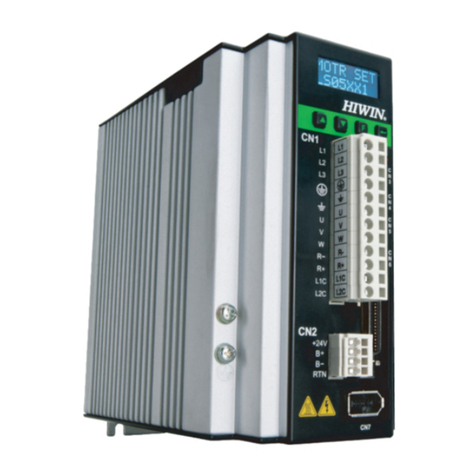
Hiwin E1 Series User manual

Electronic Cam Control System
User Manual
E1 Series Servo Drive
www.hiwinmikro.tw
MD27UE01-2203_V1.1

Revision History
The version of the manual is also indicated on the bottom of the front cover.
Release Date
Version
Applicable Product
Revision Contents
Mar. 8th, 2022
1.0
E1 series servo drive
First edition.
Mar. 8th, 2022
1.1
E1 series servo drive
Servo Drive Firmware Version.
Release Date
MD27UE01-2203_V1.1
Version

Firmware Change History
Refer to “E1 Series Servo Drive User Manual” for the information of servo drive firmware version.
Servo Drive Firmware Version
Revision Contents related to Electronic Cam Function
2.8.8
Support electronic cam control system.

Table of Contents
1. Servo Drive Specification ................................................................................................................................. 1-1
2. Introduction for Electronic Cam........................................................................................................................ 2-1
3. Setting Procedure ............................................................................................................................................ 3-1
3.1 Single axis setting........................................................................................................................... 3-3
3.2 Select electronic cam control mode................................................................................................ 3-4
3.2.1 Group communication mode.................................................................................................. 3-4
3.2.2 Pulse input mode ................................................................................................................... 3-7
3.3 Hardware configuration for communication .................................................................................... 3-8
3.4 Hardware configuration for pulse.................................................................................................... 3-9
3.5 Configuration of digital input/output signal.....................................................................................3-11
3.6 Confirmation of initial position, preset distance and material length ............................................ 3-12
3.7 Introduction for flying shear - linear system.................................................................................. 3-16
3.8 Introduction for flying shear - rotary system ................................................................................. 3-16
3.9 Electronic cam control interface setting........................................................................................ 3-17
3.9.1 Step 1: Select electronic cam mechanism ........................................................................... 3-17
3.9.2 Step 2: Set profile parameters ............................................................................................. 3-18
3.9.3 Step 3: Test run .................................................................................................................... 3-21
4. Troubleshooting................................................................................................................................................ 4-1
4.1 Enable/Disable axes in electronic cam system .............................................................................. 4-2
4.2 Motor stopping method for alarm.................................................................................................... 4-2
4.3 Relevant alarms.............................................................................................................................. 4-3

Servo Drive Specification E1 Series Servo Drive Electronic Cam Control System User Manual
1-2 HIWIN MIKROSYSTEM CORP.
MD27UE01-2203
Select the model based on electronic cam control mode.
Table 1.1
Type
Control Interface
Model
Applicable
Electronic Cam Control Mode
Standard
Voltage command
and pulse
ED1S-VN-□□□□-01-□□
Pulse input mode
ED1S-VG-□□□□-01-□□
Group communication mode
Pulse input mode
Note:
Fieldbus servo drive is not supported.

Introduction for Electronic Cam E1 Series Servo Drive Electronic Cam Control System User Manual
2-2 HIWIN MIKROSYSTEM CORP.
MD27UE01-2203
Mechanical cam exists in the physical mechanical structure, and its shape is designed based on
requirement. When the profile needs to be adjusted or modified, mechanical cam must be redesigned and
processed, which is time-consuming and inconvenient. Instead, electronic cam plans the profile via
software. It can flexibly design and adjust the profile. Without the physical cam mechanical structure, it can
also overcome the limitation of the physical mechanical cam shape, as Figure 2.1 shows. The differences
between mechanical cam and electronic cam are listed in Table 2.1.
Figure 2.1
Table 2.1
Performance
Mechanical Cam
Electronic Cam
Spatiality
Take up large space
No physical mechanical cam, space-
saving
Planning
The longer the travel distance, the bigger
the cam
No space limit, the travel distance will not
be influenced
Convenience
Not easy to modify the cam profile
Modified via software, high flexibility
Accuracy
The commands are accurate in a stable
environment
The delay error of servo and
communication must be considered
Cam mainly plans the profile relatively followed by master axis and slave axis. The typical applications are
flying shear - linear and flying shear - rotary, as Figure 2.2 shows. Generally, master axis is defined as
material feeder, and slave axis is defined as cutting axis.

E1 Series Servo Drive Electronic Cam Control System User Manual Introduction for Electronic Cam
HIWIN MIKROSYSTEM CORP. 2-3
MD27UE01-2203
Figure 2.2

Introduction for Electronic Cam E1 Series Servo Drive Electronic Cam Control System User Manual
2-4 HIWIN MIKROSYSTEM CORP.
MD27UE01-2203
(This page is intentionally left blank.)

HIWIN MIKROSYSTEM CORP. 3-1
3. Setting Procedure
3. Setting Procedure ............................................................................................................................................ 3-1
3.1 Single axis setting........................................................................................................................... 3-3
3.2 Select electronic cam control mode................................................................................................ 3-4
3.2.1 Group communication mode.................................................................................................. 3-4
3.2.2 Pulse input mode ................................................................................................................... 3-7
3.3 Hardware configuration for communication .................................................................................... 3-8
3.4 Hardware configuration for pulse.................................................................................................... 3-9
3.5 Configuration of digital input/output signal.....................................................................................3-11
3.6 Confirmation of initial position, preset distance and material length ............................................ 3-12
3.7 Introduction for flying shear - linear system.................................................................................. 3-16
3.8 Introduction for flying shear - rotary system ................................................................................. 3-16
3.9 Electronic cam control interface setting........................................................................................ 3-17
3.9.1 Step 1: Select electronic cam mechanism ........................................................................... 3-17
3.9.2 Step 2: Set profile parameters ............................................................................................. 3-18
3.9.3 Step 3: Test run .................................................................................................................... 3-21

Setting Procedure E1 Series Servo Drive Electronic Cam Control System User Manual
3-2 HIWIN MIKROSYSTEM CORP.
MD27UE01-2203
Figure 3.1 Overview of setting procedure
Refer to Figure 3.1 and the corresponding sections for the setting procedure and the description of
electronic cam control system. Before setting, ensure hardware and software configuration fits the
following requirements, or it may cause danger to the stage.
✓Same firmware version (when group communication mode is used)
✓Slave axis (cutting axis) is set to position mode (Pt000 = t.1).
✓Single axis may be driven during the process of single axis setting; therefore, to avoid causing danger
to the stage, ensure the range of motion for master axis (material feeder) will not be influenced by
that for slave axis (cutting axis).
Single axis setting
Start
Select electronic cam
control mode
Group communication
mode
Step 1:
Select electronic cam mechanism
End
Pulse input mode
Hardware
configuration for
communication
Hardware
configuration for
pulse
Configuration of
digital input/output
Confirmation of
initial position, preset
distance and
material length
Introduction for flying
shear - linear system Introduction for flying
shear - rotary system
Step 2:
Set profile parameters
Flying shear - linear
system parameters setting Flying shear - rotary
system parameters setting
Step 3: Test run
Section 3.1
Section 3.2
Section 3.2.1
Section 3.3
Section 3.2.2
Section 3.4
Section 3.5
Section 3.6
Section 3.9.1
Section 3.7
Section 3.8
Section 3.9.2
Section 3.9.2
Section 3.9.2
Section 3.9.3

E1 Series Servo Drive Electronic Cam Control System User Manual Setting Procedure
HIWIN MIKROSYSTEM CORP. 3-3
MD27UE01-2203
3.1 Single axis setting
Respectively execute single-axis initialization based on “E1 Series Servo Drive Thunder Software
Operation Manual”. The setting steps are given below.
◼To use electronic cam control mode – Group communication mode
1. Connect to master (material feeder) servo drive and execute single-axis initialization.
2. Record the positive moving direction of master (material feeder) motor.
3. Connect to slave (cutting axis) servo drive and execute single-axis initialization.
4. Record the positive moving direction of slave (cutting axis) motor, which should be the same as
the material feeding direction of master (material feeder) motor. If the directions are different,
users can change Pt000.0.
◼To use electronic cam control mode – Pulse input mode
1. Connect to slave (cutting axis) servo drive and execute single-axis initialization.
2. Record the positive moving direction of slave (cutting axis) motor, which should be the same as
the material feeding direction of master (material feeder) motor with external pulses. If the
directions are different, users can change Pt000.0.

Setting Procedure E1 Series Servo Drive Electronic Cam Control System User Manual
3-4 HIWIN MIKROSYSTEM CORP.
MD27UE01-2203
3.2 Select electronic cam control mode
E1 servo drive provides two electronic cam control modes, group communication mode and pulse input
mode. The differences between them are listed in Table 3.2.1.
Table 3.2.1
Group communication mode
Pulse input mode
Requirement of master axis
(material feeder)
E1 servo drive
E1 servo drive or other brand servo
drive
Way to group axes
Via the group communication of E1
servo drive
Via the hardware wiring configuration
of master axis’ (material feeder’s)
encoder output and slave axis’ (cutting
axis’) pulse input
Limit of number of axes
2 axes
No limit
Status monitor
The two axes can monitor each other’s
servo drive status.
The axes cannot get one another’s
servo drive status.
Alarm
If an alarm occurs on one axis, the
other one will also trigger an alarm to
decelerate and stop.
If an alarm occurs on one axis, other
axes will maintain current status. Only
when they receive the disabled signal,
they will decelerate and stop.
3.2.1 Group communication mode
All the functions of group communication mode are based on the group communication of E1 servo drive.
Therefore, users must use two E1 servo drives and establish the communication system. The setting
procedure is shown below.
1. Set group communication mode.
Respectively connect to the two servo drives and set Pt003 = t.1 based on Table 3.2.1.1. After
sending the parameter to servo drive, power cycle servo drive to make it become effective.

E1 Series Servo Drive Electronic Cam Control System User Manual Setting Procedure
HIWIN MIKROSYSTEM CORP. 3-5
MD27UE01-2203
Table 3.2.1.1
Parameter
Description
Effective
Category
Pt003
t.0
(Default)
Gantry control mode
After power on
Setup
t.1
Electronic cam control mode
(Group communication mode)
t.2
2D dynamic error compensation
control mode (Apply to GT model)
t.3
Electronic cam control mode
(Pulse input mode)
2. Build up the relationship of master axis (material feeder) and slave axis (cutting axis).
(1) Connect to master (material feeder) servo drive in Figure 3.2.1.1 and set Pt00D = t.1 based
on Table 3.2.1.2 (define it as master axis - material feeder). After sending the parameter to servo
drive, power cycle servo drive to make it become effective.
(2) Connect to slave (cutting axis) servo drive in Figure 3.2.1.1 and set Pt00D = t.0 based on
Table 3.2.1.2 (define it as slave axis - cutting axis). After sending the parameter to servo drive,
power cycle servo drive to make it become effective.
Figure 3.2.1.1

Setting Procedure E1 Series Servo Drive Electronic Cam Control System User Manual
3-6 HIWIN MIKROSYSTEM CORP.
MD27UE01-2203
Table 3.2.1.2
Parameter
Description
Effective
Category
Pt00D
t.0
Slave axis in group communication.
(Define it as cutting axis in electronic
cam control system)
After power on
Setup
t.1
Master axis in group communication.
(Define it as material feeder in
electronic cam control system)
t.2
(Default)
No group communication.
3. Open Interface signal monitor window in Thunder main window of any axis to ensure the
communication is established, as the red frame in Figure 3.2.1.2 shows.
Figure 3.2.1.2
Note: When group communication mode is used and communication system is established, alarm AL.FC0 or AL.FC1
may be triggered if users power off any of the axes. Refer to chapter 4 for cause, confirmation method and corrective
action.

E1 Series Servo Drive Electronic Cam Control System User Manual Setting Procedure
HIWIN MIKROSYSTEM CORP. 3-7
MD27UE01-2203
3.2.2 Pulse input mode
Slave axis (cutting axis) of pulse input mode receives external pulses as signal sources of master axis
(material feeder). The setting procedure is shown below.
1. Set pulse input mode.
Connect to slave (cutting axis) servo drive in Figure 3.2.2.1 and set Pt003 = t.3 based on Table
3.2.1.1. After sending the parameter to servo drive, power cycle servo drive to make it become
effective.
2. Build up slave axis (cutting axis).
Connect to slave (cutting axis) servo drive in Figure 3.2.2.1 and set Pt00D = t.0 based on Table
3.2.1.2 (define it as cutting axis). After sending the parameter to servo drive, power cycle servo drive
to make it become effective.
3. Set Pt200 based on the encoder format. For example, if the encoder format is AqB, set Pt200 =
t.4 (Differential pulse signal with 90 degrees phase difference). After sending the parameter to
servo drive, power cycle servo drive to make it become effective.
4. Ensure the pulse relationship of master axis (material feeder) and slave axis (cutting axis).
Move master axis (material feeder) for a short distance. Open Interface signal monitor window in
Thunder main window of slave axis (cutting axis) to check if the value of the input column for pulse
command, the accumulated direction and the ratio are correct.
Figure 3.2.2.1

Setting Procedure E1 Series Servo Drive Electronic Cam Control System User Manual
3-8 HIWIN MIKROSYSTEM CORP.
MD27UE01-2203
3.3 Hardware configuration for communication
When group communication mode is used, connect two servo drives via CN8 with the communication
cable, as Figure 3.3.1 shows. The specification of servo drive communication cable is given in Figure 3.3.2
and Table 3.3.1.
Figure 3.3.1 CN8 position
Figure 3.3.2 Servo drive communication cable (for gantry control system)
Table 3.3.1 Communication cable for gantry function
Name
HIWIN Part
Number
Description
Servo drive
communication
cable
HE00EJ6DD000
Connect two servo drives which both support gantry function via CN8.
(0.5 m)
Note:
The way for group communication mode to group axes is the same as that of gantry function. Therefore, they use
the same servo drive communication cable.
Standard
Servo drive 1 CN8
Servo drive 2 CN8

E1 Series Servo Drive Electronic Cam Control System User Manual Setting Procedure
HIWIN MIKROSYSTEM CORP. 3-9
MD27UE01-2203
3.4 Hardware configuration for pulse
When pulse input mode is used, connect the encoder output pin of master (material feeder) servo drive to
the pulse input pin of salve (cutting axis) servo drive.
If E1 servo drive is used as master axis (material feeder), its encoder output pin can simultaneously
connect to the pulse input pin of multiple salve axes (cutting axes), as Figure 3.4.1 shows. As master axis
(material feeder), E1 servo drive can set the resolution of one revolution of motor to Pt212 (refer to section
8.6 in “E1 Series Servo Drive User Manual”). By doing so, master axis (material feeder) will send pulse
signals to salve axis (cutting axis) according to the encoder output ratio.
Besides, other brand servo drive or frequency converter can also be used as master (material feeder)
servo drive. Just connect its encoder output pin to the pulse input pin of salve (cutting axis) servo drive,
and ensure the ratio and the direction are correct.
Figure 3.4.1 Wiring diagram for pulse input mode
Note:
If there is a limit for encoder output bandwidth of master axis (material feeder), users can set ECAM_PulseGain of
slave axis (cutting axis) to adjust the receiving ratio. Based on the formula “Resolution of master axis (material feeder)
= Pt212 x ECAM_PulseGain”, users must set the correct Pt212 in master axis (material feeder) and the correct
ECAM_PulseGain in slave axis (cutting axis). Otherwise, slave axis (cutting axis) cannot receive the correct pulse
Master
Slave 1
Slave 2
Slave N
Master
Slave

Setting Procedure E1 Series Servo Drive Electronic Cam Control System User Manual
3-10 HIWIN MIKROSYSTEM CORP.
MD27UE01-2203
signals. For example, take E1 servo drive as master axis (material feeder), its resolution of motor is 8,388,608
count/rev. Therefore, Pt212 in master axis (material feeder) can be set as 4,194,304, and ECAM_PulseGain in slave
axis (cutting axis) can be set as 2. Go to Others tab in Thunder “Parameters Setup” window to set ECAM_PulseGain.
Its value (int type) will become effective after power on.
Other manuals for E1 Series
5
Table of contents
Other Hiwin Servo Drive manuals