manuals.online logo
Brands
  1. Home
  2. •
  3. Brands
  4. •
  5. HK Instruments
  6. •
  7. Measuring Instrument
  8. •
  9. HK Instruments CDT2000 Series User manual

HK Instruments CDT2000 Series User manual

Copyright HK Instruments 2022 www.hkinstruments. Installaon version 9.0 2022
INSTALLATION
INSTRUCTIONS
CARBON DIOXIDE TRANSMITTERS
CDT2000 Series
• READ THESE INSTRUCTIONS CAREFULLY BEFORE ATTEMPTING
TO INSTALL, OPERATE OR SERVICE THIS DEVICE.
• Failuretoobservesafetyinformaonandcomplywithinstrucons
canresultinPERSONALINJURY,DEATHAND/ORPROPERTY
DAMAGE.
• Toavoidelectricalshockordamagetoequipment,disconnect
powerbeforeinstallingorservicinganduseonlywiringwith
insulaonratedforfulldeviceoperangvoltage.
• Toavoidpotenalreand/orexplosiondonotuseinpotenally
ammableorexplosiveatmospheres.
• Retaintheseinstruconsforfuturereference.
• Thisproduct,wheninstalled,willbepartofanengineeredsystem
whosespecicaonsandperformancecharacteriscsarenot
designedorcontrolledbyHKInstruments.Reviewapplicaons
andnaonalandlocalcodestoassurethattheinstallaonwill
befunconalandsafe.Useonlyexperiencedandknowledgeable
technicianstoinstallthisdevice.
•Fuseatloadsupply(normally6A,10A,16A)doesnotalwayslimit
therelayoutputloadcurrentto6A.RelayMaximumLoad(250Vx
6Ares.)
•Addanexternalfusetorelaycommonconnector.Useame-lag
 fuse(max6A)thatisinaccordancewiththestandardIEC60127-2.
 Theproductdoesn’thaveaninternalfusefortherelay.
 CAUTION:Theproductmayonlybeconnectedtoovervoltage
 categoryIIelectricitynetworkaccordingtoIEC60664-1.
SPECIFICATIONS
ThankyouforchoosinganHKInstrumentsCDT2000seriescarbon
dioxidetransmier.TheCDT2000seriesisintendedforuseincom-
mercialenvironmentsinHVAC/Rapplicaons.
TheCDT2000seriesmeasurescarbondioxide(CO2),ulizingthein-
dustrystandardNDIRmeasurementprinciple,andtemperature(T).
Oponalrelavehumidity(rH)measurementisalsoavailableinthe
samedevice.Eachmeasurementparameter(CO2,rH,T)hasasepa-
rateeldcongurableoutput.
TheCDT2000seriescarbondioxidetransmiersareavailablewith
Modbusconguraon,relayandtouchscreendisplay.
The CDT2000 series transmiers calibrate themselves automa-
callyusingABCTMlogic.TheABCTMlogicrequiresthatthespacein
which the transmier is used needs to to be unoccupied for four
hoursperdaysothattheindoorCO2concentraondropstotheout-
sidelevel.CDT2000-DCisadualchannelmodelwithameasuring
channelandareferencechannelthatmakesaconnuouscompari-
sonandthenecessaryadjustmentaccordingly.CDT2000-DCisalso
suitableforbuildingsthatareconnuouslyoccupied.
•humidityinvariousindustrialapplicaons
•temperaturesinHVAC/Renvironment
•CDT2000-DCseriesdevicescanalsobeusedinapplicaonswhere
thereisaconstantsourceofcarbondioxidepresent(forexample
hospitalsandgreenhouses)
SPECIFICATIONS
Performance
Measurement ranges:
CO2:400–2000ppm
Temperature:0...50°C
Relavehumidity:0–100%
Accuracy:
CO2:±40ppm+3%ofreading,DCmodel:75ppmor
10%ofreading(whicheverisgreater)
Temperature:<0.5ºC
Relavehumidity:±2...3%at0...50°Cand10–90%rH
Totalerrorbandincludesaccuracy,hysteresisand
temperatureeectover5...50°Cand10–90%rH.
Technical Specicaons
Media compability:
Dryairornon-aggressivegases
Measuring units:
ppm,°Cand%rH
Measuring element:
CO2:Non-dispersiveinfrared(NDIR)
Temperature: Pt1000(modelswithoutrH-measurement
  Integrated(modelswithrH-measurement)
Relavehumidity:Thermosetpolymercapacive
sensingelement
Calibraon:
Automacself-calibraonABCLogicTMorconnuous
comparison(DC)
Environment:
Operangtemperature:0...50°C
Storagetemperature:-20...70°C
Humidity:0to95%rH,noncondensing
Physical
Dimensions:
Case:99x90x32mm
Weight:
150g
Mounng:
3screwholessloed,3.8mm
Materials:
Case: ABS
Protecon standard:
IP20
Display (Oponal)
Touchscreen
Size:77.4x52.4mm
Electrical connecons:
Powersupply:
 5-screwterminalblock
 (24V,GND,CO2,rH,T)
 0.2–1.5mm2(16–24AWG)
Relay out:
 3-screwterminalblock
 (NC,COM,NO)
 0.2–1.5mm2(16–24AWG)
Electrical
Input: 24VACorVDC,±10%
 Currentconsumpon:max90mA(at24V)+ 
 10mAforeachvoltageoutputor20mAfor 
 eachcurrentoutput
Outputsignal(CO2,rH,temperature):
 0–10V,R>1kΩ
 2–10V,R>1kΩ(oponalvoltageoutput,displayrequired)
 4–20mA,R<500Ω
Relay out:
 SPDTRelay,250VAC/30VDC/6A
 Adjustableswitchingpointandhysteresis
Conformance
Meetsrequirementsfor:
  CE:  UKCA:
EMC:  2014/30/EU S.I.2016/1091
RoHS:  2011/65/EU S.I.2012/3032
LVD/EESR: 2014/35/EU S.I.2016/1101
WEEE:  2012/19/EU S.I.2013/3113
INTRODUCTION
APPLICATIONS
WARNING
CDTseriesdevicesarecommonlyusedtomonitor:
• CO2andhumiditylevelsinoces,publicspaces,meengrooms
andclassrooms
• CO2levelsofreturnairinvenlaonsystems
•incomingairandreturnairhumiditylevelsinvenlaonsystem
RoHS
COMPLIANT

Copyright HK Instruments 2022 www.hkinstruments. Installaon version 9.0 2022
SCHEMATICS
DIMENSIONAL DRAWINGS
INSTALLATION
STEP 1: MOUNTING THE DEVICE
1)Mountthedeviceinthedesiredlocaon(seestep1).
2)Routethecablesandconnectthewires(seestep2).
3)Thedeviceisnowreadyforconguraon.
WARNING!Applypoweronlyaerthedeviceisproperlywired.
Figure 1a - Surface mounng
1)Selectamounnglocaononthewallat1.2–1.8m(4–6)above
theoorandatleast50cm(20in)fromtheadjacentwall.Do
notblockdeviceairventsfromanydireconandleaveatleast
20cm(8in)gaptootherdevices.Locatetheunitinanareawith
goodvenlaonandanaveragetemperature,whereitwillbe
responsivetochangestotheroomcondions.TheCDTshouldbe
mountedonaatsurface.
DonotlocatetheCDTwhereitcanbeaectedby:
•Directsunlight
•Drasordeadareasbehinddoors
•Radiantheatfromappliances
•Concealedpipesorchimneys
•Outsidewallsorunheated/uncooledareas
2)Usethedeviceasatemplateandmarkthescrewholes.
3)Mountthewallplatewithscrews.
•Incorrectinstallaonmaycauseashiintemperatureoutput
•Securethelidwithalockingscrew,iftherelayisconnectedtothe
mainspower.
Display locking
jumper
Output mode
selecon
jumpers
Contact pins for
relay terminal
Contact pins for
terminal block
Terminal block
Terminal block for relay
99.0
90.0
83.0
49.5
14.0
45.0
18.0
Ø 4.0
32.0
YES NO NO
Figure 1b - Mounng orientaon
Copyright HK Instruments 2022 www.hkinstruments. Installaon version 9.0 2022
CAUTION!
•ForCEcompliance,aproperlygroundedshieldingcableis
required.
•Usecopperwireonly.Insulateorwirenutallunusedleads.
•Supplyaseparatecableforrelayandsignaloutwhenusingline
voltagetopowertherelay.
•Anywiringmaycarrythefulloperanglinevoltagecurrentbased
oneldinstallaon.Thecoverlockingscrewmustbeinstalledif
thelinevoltageissuppliedtotherelay.
•Careshouldbeusedtoavoidelectrostacdischargetothedevice.
•Thisunithasconguraonjumpers.Youmayneedtorecongure
thisdeviceforyourapplicaon.
1)Routethecablesthroughthesquareopeninginthebackplateor
forsurfacewiringselectaknockoutonthetoporboomofthe
wallplate,asshowninFigure2a.
2)ConnectthewiresasshowninFigure2band2c.
WIRING DIAGRAMS CONTINUED
Figure 2a - Roung the cables
24 V
GND
CO2
rH
Temp
+
Output 0/2–10 V / 4–20 mA
Figure 2b - Wiring diagram: Power input & signal output
Wires can be routed through the square opening in the back plate
Wires can be routed through the top knockouts
Wires can be routed through the boom knockouts
Figure 2d - Wiring diagram: Relay
NC
COM
NO
STEP 2: WIRING DIAGRAMS
NOTE!Whenusinglongconneconwiresitmaybenecessarytousea
separateGNDwireforvoltageoutputcurrenttopreventmeasurement
distoron.TheneedforanextraGNDwiredependsonthecrosssec-
onandlengthoftheusedconneconwires.Iflongand/orsmallcross
seconwiresareused,supplycurrentandwireresistancemaygener-
ate avoltage drop in thecommon GND wire resulng ina distorted
outputmeasurement.
24 V
GND
CO
2
rH
+
Temp
V V V
Output 0/2...10 V
Output 0/2...10 V
Output 0/2...10 V
Figure 2c - Wiring diagram: Extra GND wire
STEP 3: CONFIGURATION
ConguraonoftheCDTseriesdeviceconsistsof:
1)Conguringthejumpers(seestep4).
2)Conguraonmenuopons.
(Display-andModbusversionsonly.Seetheusermanualfor
furtherdetails.)
Copyright HK Instruments 2022 www.hkinstruments. Installaon version 9.0 2022
1)Conguraonoftheoutputmodesof:
•Carbondioxide(CO2)
•Relavehumidity(rH)
•Temperature(Temp)
Selecttheoutputmode,current(4–20mA)orvoltage(0–10V),
byinstallingjumpersasshowninFigure4.Eachoutputarecong-
uredseparately.
Toselect2–10Voutputmodeonadisplayversionofthedevice:
First,select0–10Voutputbyjumper(s),thenchangethevoltage(V)
outputfrom0–10Vto2–10Vviatheconguraonmenu.Please
seetheusermanualformoredetails.
Thesellerisobligatedtoprovideawarrantyofveyearsforthedeliv-
eredgoodsregardingmaterialandmanufacturing.Thewarrantyperiod
isconsideredtostartonthedeliverydateoftheproduct.Ifadefect
inrawmaterialsoraproduconawisfound,thesellerisobligated,
whentheproductissenttothesellerwithoutdelayorbeforeexpira-
onofthewarranty,toamendthemistakeathis/herdiscreoneither
by repairing the defecve product or by delivering free of charge to
thebuyeranewawlessproductandsendingittothebuyer.Delivery
costsfortherepairunderwarrantywillbepaidbythebuyerandthe
return costs by the seller. The warranty does not comprise damages
causedbyaccident,lightning,oodorothernaturalphenomenon,nor-
malwearandtear,improperorcarelesshandling,abnormaluse,over-
loading,improperstorage,incorrectcareorreconstrucon,orchanges
and installaonwork notdoneby theseller.Theselecon ofmateri-
alsfordevicespronetocorrosionisthebuyer’sresponsibility,unless
otherwise is legally agreed upon. Should the manufacturer alter the
structureofthedevice,thesellerisnotobligatedtomakecomparable
changestodevicesalreadypurchased.Appealingforwarrantyrequires
thatthebuyerhascorrectlyfullledhis/herduesarisenfromthede-
liveryandstatedinthecontract.Thesellerwillgiveanewwarrantyfor
goodsthathavebeenreplacedorrepairedwithinthewarranty,how-
everonlytotheexpiraonoftheoriginalproduct’swarrantyme.The
warrantyincludestherepairofadefecvepartordevice,orifneeded,
anewpartordevice,butnotinstallaonorexchangecosts.Underno
circumstanceisthesellerliablefordamagescompensaonforindirect
damage.
Jumper installed to the le side pins:
0–10 V output selected
CO2
rH
Temp
0–10 V 4–20 mA
Jumper installed to the right side pins:
4–20 mA output selected
CO2
rH
Temp
0–10 V 4–20 mA
First jumper installed to the right side pins:
4–20 mA output selected for CO2
Second and third jumper installed to the le side pins
0–10 V outputs selected for relave humidity & temperature
CO2
rH
Temp
0–10 V 4–20 mA
Figure 4
STEP 4: Jumper settings RECYCLING/DISPOSAL
The parts le over from installaon should be
recycled according to your local instrucons.
Decommissioned devices should be taken to a
recyclingsitethatspecializesinelectronicwaste.
WARRANTY POLICY
(Grey colour indicates that a jumper is installed)
No jumper
Circuit open
Jumper installed
Circuit closed
Jumper stored
Figure 3 - Jumper installaon
2)Lockingthedisplay:
Installthejumpertolockthedisplaytopreventaccesstothecongu-
raonmenuaerinstallaoniscompleted(seetheschemacsforthe
locaonofthepins).

Other HK Instruments Measuring Instrument manuals

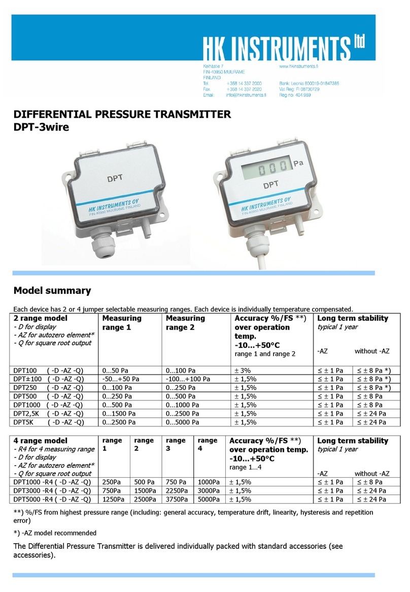
HK Instruments DPT100 User manual

HK Instruments

HK Instruments DPT100 User manual

HK Instruments PHM-V1 User manual

HK Instruments

HK Instruments PHM-V1 User manual

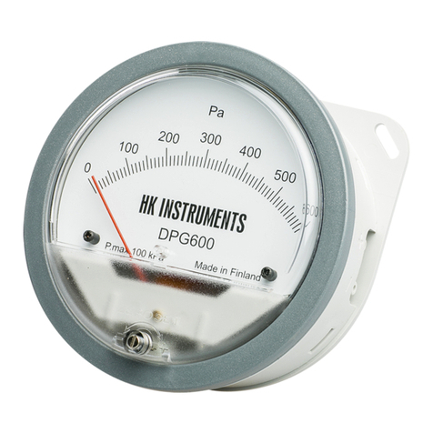
HK Instruments DPG Series User manual

HK Instruments

HK Instruments DPG Series User manual

HK Instruments DPI+/-500-D User manual

HK Instruments

HK Instruments DPI+/-500-D User manual

HK Instruments DPG Series User manual

HK Instruments

HK Instruments DPG Series User manual

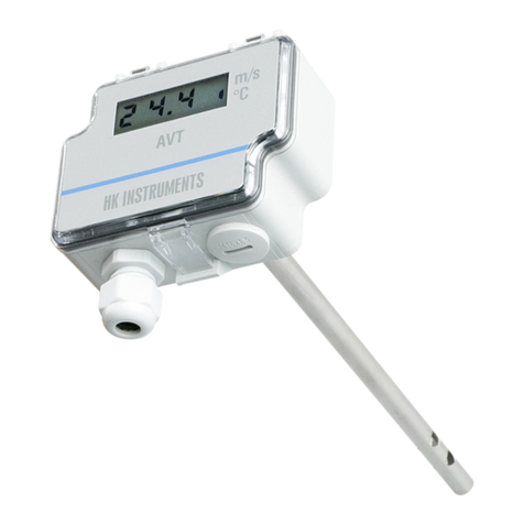
HK Instruments AVT Series User manual

HK Instruments

HK Instruments AVT Series User manual

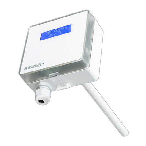
HK Instruments CDT 2000 Duct Series User manual

HK Instruments

HK Instruments CDT 2000 Duct Series User manual

HK Instruments DPT-R8 Series User manual

HK Instruments

HK Instruments DPT-R8 Series User manual

HK Instruments DPT-PRIIMA-MOD Series User manual

HK Instruments

HK Instruments DPT-PRIIMA-MOD Series User manual

HK Instruments MM Series User manual

HK Instruments

HK Instruments MM Series User manual

Popular Measuring Instrument manuals by other brands

Nikon XF SERIES quick start guide

Nikon

Nikon XF SERIES quick start guide

Bender ISOMETER isoES425 quick start guide

Bender

Bender ISOMETER isoES425 quick start guide

Hanna Instruments HI 739 Quick reference guide

Hanna Instruments

Hanna Instruments HI 739 Quick reference guide

Flexim FLUXUS WD200 user manual

Flexim

Flexim FLUXUS WD200 user manual

LINSHANG LS108A instruction manual

LINSHANG

LINSHANG LS108A instruction manual

TESTO 206 instruction manual

TESTO

TESTO 206 instruction manual

Dover Civacon ROM III Installation & operation manual

Dover

Dover Civacon ROM III Installation & operation manual

Mantech T10 Operation manual

Mantech

Mantech T10 Operation manual

LaserLiner LaserRange-Master i3 manual

LaserLiner

LaserLiner LaserRange-Master i3 manual

Svantek Shawcity SVAN 977C user manual

Svantek

Svantek Shawcity SVAN 977C user manual

Seaward Solar Survey 200R manual

Seaward

Seaward Solar Survey 200R manual

Illuminati IM150 quick start guide

Illuminati

Illuminati IM150 quick start guide

Campbell CS615 instruction manual

Campbell

Campbell CS615 instruction manual

WellMark 6900 Series Installation, operation & maintenance instructions

WellMark

WellMark 6900 Series Installation, operation & maintenance instructions

Quest Engineering VI-410 Technical tips

Quest Engineering

Quest Engineering VI-410 Technical tips

senva TotalSense Series Navigation Guide

senva

senva TotalSense Series Navigation Guide

KROHNE BM 26 BASIC Supplementary instructions

KROHNE

KROHNE BM 26 BASIC Supplementary instructions

KVH Industries 1775 IMU Technical manual

KVH Industries

KVH Industries 1775 IMU Technical manual

manuals.online logo
manuals.online logoBrands
  • About & Mission
  • Contact us
  • Privacy Policy
  • Terms and Conditions

Copyright 2025 Manuals.Online. All Rights Reserved.