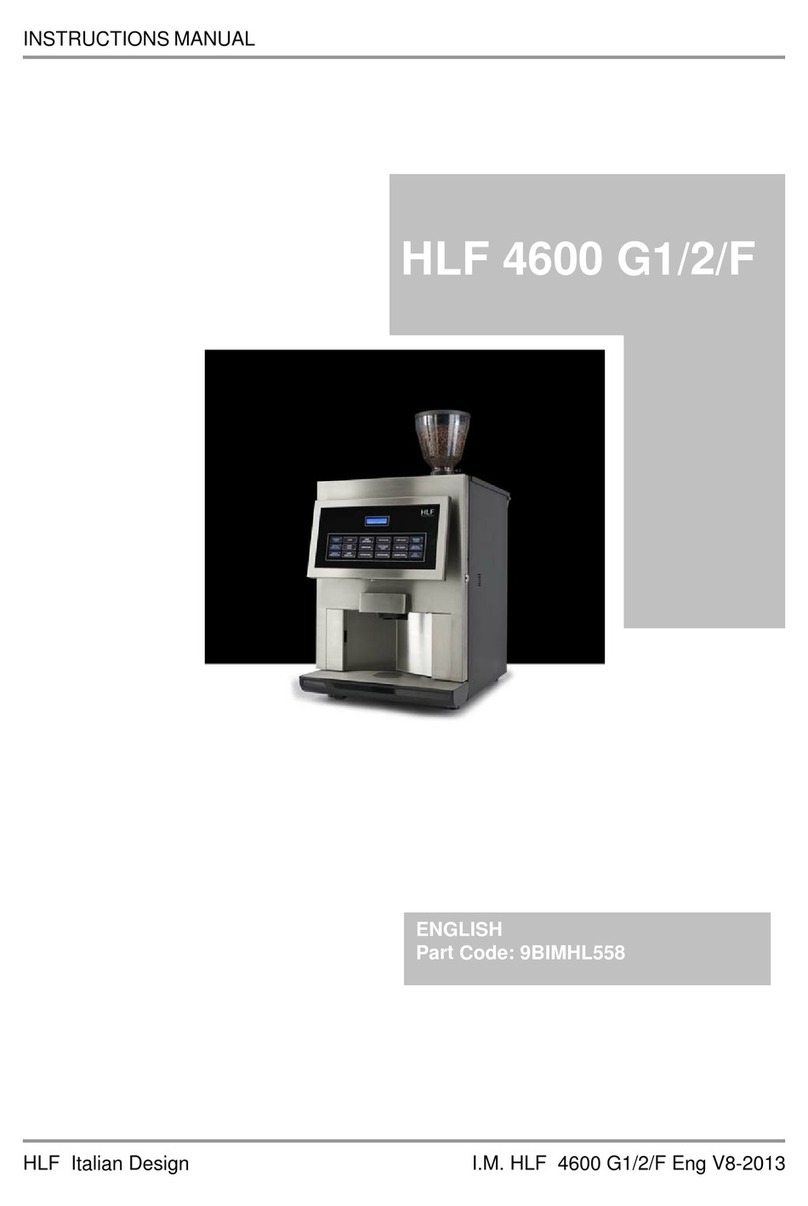
HLF Italian Design HLF 4600 G1 User manual

SERVICE MANUAL
I
HLF Italian Design S.M. HLF 4600 G1-G2-F Eng V3-2013
HLF 4600 G1/2/F
ENGLISH

SERVICE MANUAL
HLF Italian Design S.M. HLF 4600 G1-G2-F Eng V3-2013
RETAIN FOR FUTURE USE !
The copyright of these Service Manual, which are entrusted to the recipient personally,
remains with the HLF company.
The content may not be disclosed or made available to any third party without the
express consent of the HLF company.
These Operating Instructions must be read and applied by anyone performing work with
or on the equipment described.
In particular, it is imperative that all such persons familiarise themselves with the safety
instructions.

TABLE OF CONTENTS
S.M. HLF 4600 G1-G2-F Eng V3-2013 I HLF Italian Design
1User manual........................................................................................................1-1
2Exploded diagrams ............................................................................................2-1
2.1.1 General exploded diagram (4600 G1)...........................................2-1
2.1.2 General exploded diagram (4600 G2)...........................................2-3
2.2 Water boiler exploded diagram................................................................2-5
2.3 Steam boiler exploded diagram...............................................................2-6
2.4 Solenoid valves set exploded diagram ....................................................2-8
2.5 Air solenoid valve set...............................................................................2-9
2.6 Power supply unit exploded diagram.....................................................2-10
3 3-1
4Ordinary maintenance........................................................................................4-1
4.1 Removing the coffee group......................................................................4-1
4.2 Sealing and filter replacement (10000 Cycles Kit Installation).................4-2
4.3 Coffee Gear Motor Cam Adjustment......................................................4-10
4.4 Grinder blades replacement ..................................................................4-12
4.4.1 Grinder blades replacement (only for 4600 G1)..........................4-12
4.4.2 Grinder blades replacement (only for 4600 G2)..........................4-16
5 5-1
6Extraordinary maintenance...............................................................................6-1
6.1 Removing the various metal plates..........................................................6-1
6.1.1 Removing the air solenoid valves set............................................6-1
6.1.2 Removing the door board cover....................................................6-2
6.1.3 Removing the side panels.............................................................6-3
6.1.4 Removing the power supply unit...................................................6-1
7 7-1

TABLE OF CONTENTS
HLF Italian Design II S.M. HLF 4600 G1-G2-F Eng V3-2013
8Removing components......................................................................................8-1
8.1.1 Removing the grinder / doser (only for 4600 G1)..........................8-1
8.1.2 Removing the grinder / doser (only for 4600 G2)..........................8-5
8.2 Removing the transformer.......................................................................8-9
8.3 Removing the flow meter.......................................................................8-10
8.4 Removing the drip tray micro switch......................................................8-11
8.5 Removing the coffee gear motor............................................................8-12
8.6 Removing the door micro switch............................................................8-13
8.7 Removing the door board......................................................................8-14
8.8 Removing the LCD display ....................................................................8-15
8.9 Removing the soft touch panel ..............................................................8-16
8.10 Removing the net filter...........................................................................8-17
8.11 Removing the air solenoid valves..........................................................8-18
8.12 Removing the door locker......................................................................8-19
9 9-1
10 Operations on the hydraulic circuit................................................................10-1
10.1 Cooling down.........................................................................................10-1
10.2 Emptying the boilers..............................................................................10-2
10.3 Removing the solenoid valve set...........................................................10-3
10.4 Removing the steam outlet solenoid valve ............................................10-4
10.5 Removing the coffee group plate...........................................................10-5
10.6 Removing the water boiler.....................................................................10-6
10.7 Removing the steam boiler....................................................................10-1
11 11-1

TABLE OF CONTENTS
S.M. HLF 4600 G1-G2-F Eng V3-2013 III HLF Italian Design
12 Operating the computer software...................................................................12-1
12.1 Gaining access to the machine software...............................................12-1
12.2 Programming Steps...............................................................................12-1
12.3 Programming Menu...............................................................................12-4
12.3.1 Settings.......................................................................................12-4
12.3.2 Money Value.............................................................................12-14
12.3.3 Drink Price.................................................................................12-16
12.3.4 Change Password.....................................................................12-16
12.3.5 Set Factory Data.......................................................................12-17
13 Software Table..................................................................................................13-1
14 14-1
15 Troubleshooting...............................................................................................15-1
15.1 Error messages .....................................................................................15-1
15.1.1 Out Of Coffee..............................................................................15-1
15.1.2 Check Grinder.............................................................................15-2
15.1.3 Drip Tray Full...............................................................................15-3
15.1.4 Flow Meter K.O...........................................................................15-4
15.1.5 Coffee Gear Motor ......................................................................15-5
15.1.6 Temp Sensor K.O. ......................................................................15-6
15.1.7 Check Water ...............................................................................15-7
15.1.7.1How to unblock the main inlet water valve ............................15-8
15.1.8 Serial Time Out...........................................................................15-9
15.1.9 Clean Cof. Group........................................................................15-9
15.1.10 Door Open.................................................................................15-10
15.1.11 Descaling / Filter .......................................................................15-11
15.1.12 Grounds Drawer........................................................................15-12
15.1.13 Entire Cleaning Required..........................................................15-13
15.2 Strange behaviours..............................................................................15-14
15.2.1 The LCD display is blanked or shows lots of squares...............15-14
15.2.2 The drinks are cold....................................................................15-14
15.2.3 “Wait for Heating” stays all the time on the display ...................15-14
15.2.4 “ENTIRE CLEANING” and all the instructions for the “Entire
Cleaning” routine, appear straight away even when just switch ON the
machine. ..................................................................................................15-15
TABLE OF CONTENTS
HLF Italian Design IV S.M. HLF 4600 G1-G2-F Eng V3-2013
16 Electronic boards description.........................................................................16-1
16.1 Main board.............................................................................................16-2
16.2 Door board.............................................................................................16-4
16.3 Water level board / Steam boiler water level board ...............................16-5
16.4 Power stabilizer .....................................................................................16-6
17 Planning diagram .............................................................................................17-1
18 Electric diagram ...............................................................................................18-1
19 Hydraulic circuit...............................................................................................19-1
20 Spare part list ...................................................................................................20-1

USER MANUAL
S.M. HLF 4600 G1-G2-F Eng V3-2013 1-1 HLF Italian Design
1 User manual


EXPLODED DIAGRAM
S.M. HLF 4600 G1-G2-F Eng V3-2013 2-1 HLF Italian Design
2 Exploded diagrams
2.1.1 General exploded diagram (4600 G1)
1. Coffee doser
2. Mixing bowl
3. Air solenoid valves set
4. Coffee group
5. Milk frother
6. Drip tray micro switch cover plate
7. Ground drawer

EXPLODED DIAGRAM
HLF Italian Design 2-2 S.M. HLF 4600 G1-G2-F Eng V3-2013
1. Power stabilizer
2. Main board
3. Water level board
4. Solenoid valves set
5. Coffee gear motor
6. Water boiler
7. Air-break
8. Power supply unit

EXPLODED DIAGRAM
S.M. HLF 4600 G1-G2-F Eng V3-2013 2-3 HLF Italian Design
2.1.2 General exploded diagram (4600 G2)
1. Coffee Doser
2. Mixing bowl
3. Air solenoid valves set
4. Coffee group
5. Milk frother
6. Drip tray micro switch cover plate
7. Ground drawer

EXPLODED DIAGRAM
HLF Italian Design 2-4 S.M. HLF 4600 G1-G2-F Eng V3-2013
1. Power stabilizer
2. Main board
3. Water level board
4. Solenoid valves set
5. Coffee gear motor
6. Water boiler
7. Air-break
8. Power supply unit

EXPLODED DIAGRAM
S.M. HLF 4600 G1-G2-F Eng V3-2013 2-5 HLF Italian Design
2.2 Water boiler exploded diagram
1. Temperature probe
2. Heating element
3. Manual thermostat
4. Automatic thermostat
5. Straight push fitting for the
coffee solenoid valve pipe
6. Straight push fitting for the
solenoid valve set pipe
7. Elbow push fitting for the
water pump

EXPLODED DIAGRAM
HLF Italian Design 2-6 S.M. HLF 4600 G1-G2-F Eng V3-2013
2.3 Steam boiler exploded diagram

EXPLODED DIAGRAM
S.M. HLF 4600 G1-G2-F Eng V3-2013 2-7 HLF Italian Design
1. Straight fitting w/ olive connected to n. 18
2. Water level probe
3. Elbow fitting w/ olive connected to n. 12
4. Manual thermostat
5. Automatic thermostat
6. Anti – vacuum valve
7. Elbow push fitting connected to n. 11
8. Steam boiler
9. Steam boiler heating element
10. Elbow push fitting connected to steam inlet solenoid valve
11. Elbow fitting w/ olive connected to n. 7
12. Elbow push fitting connected to n. 3
13. Elbow push fitting connected to milk frother pipe
14. Steam outlet solenoid valve
15. Outlet for steam wand solenoid valve
16. Over pressure valve 6 bar
17. Pressure switch
18. Elbow push fitting connected to n. 1
19. Steam boiler water level board
20. One way valve

EXPLODED DIAGRAM
HLF Italian Design 2-8 S.M. HLF 4600 G1-G2-F Eng V3-2013
2.4 Solenoid valves set exploded diagram
1. Elbow push fittings
connected to numbers 3
2. Straight push fitting for
steam boiler inlet solenoid
valve pipe
3. Elbow push fittings
connected to numbers 1
4. Overpressure valve 16
bar
5. Discharge solenoid valve
6. Mixer 1 solenoid valve
7. Mixer 2 solenoid valve
8. Hot water solenoid valve
9. Steam boiler inlet
solenoid valve

EXPLODED DIAGRAM
S.M. HLF 4600 G1-G2-F Eng V3-2013 2-9 HLF Italian Design
2.5 Air solenoid valve set
1. Froth milk air regulator
2. Flat milk air regulator
3. T plastic connector
4. Froth milk solenoid valve
5. Anti-return solenoid valve
6. Anti-return air regulator
7. Milk frother air pipe

EXPLODED DIAGRAM
HLF Italian Design 2-10 S.M. HLF 4600 G1-G2-F Eng V3-2013
2.6 Power supply unit exploded diagram
1. Flow Meter
2. Water Pump
3. Fan
4. Connection to Milk Fridge
5. Main inlet water valve
6. Power cord socket
7. Main Switch
8. Net Filter
9. Transformer

S.M. HLF 4600 G1-G2-F Eng V3-2013 3-1 HLF Italian Design
3

This manual suits for next models
2
Table of contents
Other HLF Italian Design Coffee Maker manuals

HLF Italian Design
HLF Italian Design 5500F User manual

HLF Italian Design
HLF Italian Design Aroma 4500 User manual

HLF Italian Design
HLF Italian Design 1700 User manual

HLF Italian Design
HLF Italian Design 3600 User manual

HLF Italian Design
HLF Italian Design 5500 User manual

HLF Italian Design
HLF Italian Design 1700 User manual

HLF Italian Design
HLF Italian Design 4600 G1 User manual

HLF Italian Design
HLF Italian Design 2700 Programming manual

HLF Italian Design
HLF Italian Design AROMA 4000 User manual

HLF Italian Design
HLF Italian Design 2700 User manual