HNC Electric HV350 Series User manual

HV350 Series Mini Frequency Inverter
User Manual
HNC Electric Limited

HV350 Mini Frequency Inverter User Manual
Contents
Chapter 1 Introduction to HV350 Series Inverter ...............................................................................3
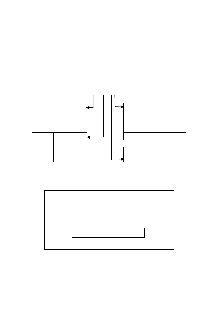
1.1 Product Model Description..................................................................................................................3
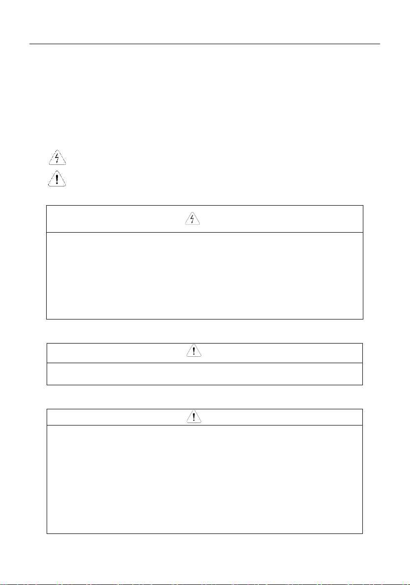
1.2 Safe Precaution..................................................................................................................................4
1.3 Product Series....................................................................................................................................7
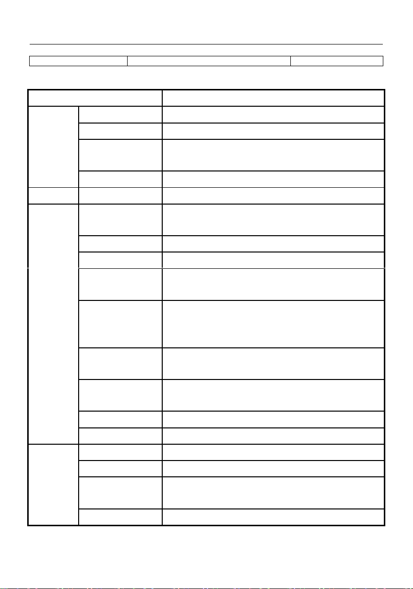
1.4 Product Specifications........................................................................................................................8
1.5 Product Component Name...............................................................................................................10
1.6 Product Outline, Mounting Dimension, and Weight ...........................................................................10
1.7 Operation Panel Outline and Mounting Dimension............................................................................11
1.8 Braking Resistor Lectotype...............................................................................................................11
Chapter 2 Inverter Installation...........................................................................................................12
2.1 Environment for Product Installation.................................................................................................12
2.2 Mounting Direction and Space..........................................................................................................12
2.3 Removal and Mounting of Operation Panel and Cover......................................................................13
Chapter 3 Wiring of Inverter..............................................................................................................16
3.1 Connection of the Product and Peripheral Devices ...........................................................................16
3.2 Description of Peripheral Devices for Main Circuit.............................................................................17
3.3 Lectotype of mMain Circuit Peripheral Devices.................................................................................18
3.4 Product Terminal Configuration.........................................................................................................18
3.5 Functions of Main Circuit Terminal....................................................................................................18
3.6 Attention for Main Circuit Wiring........................................................................................................20
3.7 Terminal Wiring ................................................................................................................................20
3.8 Functions of Control Circuit Terminals...............................................................................................21
3.9 Lectotype of Control Circuit Peripheral Devices ................................................................................23
Chapter 4 Using Instructions of Operation Panel ............................................................................24
4.1 Introduction to Operation Panel........................................................................................................24
4.2 Descriptions of Indicators .................................................................................................................25
4.3 Description of Keys on Operation Panel............................................................................................25
4.4 Keypad Operating Status..................................................................................................................25
4.5 Panel Operation Method...................................................................................................................25
4.6 Parameter Display............................................................................................................................28
4.7 Motor auto-tuning procedure ............................................................................................................29
4.8 Running for the First Time................................................................................................................29
Chapter 5 List of Parameters ............................................................................................................30
5.1 Function Parameter Table.................................................................................................................30
Chapter6 Detail Function Introduction................................................................................................49
P0 Basic function parameters.................................................................................................................49
P1 Auxiliary function parameters 1 .........................................................................................................54
P2 Auxiliary function parameters 2 .........................................................................................................58

HV350 Mini Frequency Inverter User Manual
P3 Motor parameters..............................................................................................................................63
P4 Dedicatd function for V/F control.....................................................................................................64
P5 Vector control funtion........................................................................................................................66
P6 I/O I/O output terminal.......................................................................................................................70
P7 Analog input terminal function ...........................................................................................................83
P8 Analog output terminal ......................................................................................................................85
P9 Program operating parameters..........................................................................................................87
PA PID parameter ..................................................................................................................................90
Pb Traverse function..............................................................................................................................93
PC Communication and Bus control function..........................................................................................95
Pd Faults and protection parameters......................................................................................................96
PE Factory reserved ..............................................................................................................................99
PF Factory reserved...............................................................................................................................99
PH Display function................................................................................................................................99
Chapter 7 Fault diagnosis and troubleshooting...............................................................................100
7.1 Fault query at fault..........................................................................................................................100
7.2 List of Fault andAlarm Information .................................................................................................101
7.3 Troubleshooting Procedures...........................................................................................................104
Chapter 8 Routine Repair and Maintenance .....................................................................................106
8.1 Routine Maintenance .....................................................................................................................106
8.2 Periodic Maintenance.....................................................................................................................107
8.3 Component Replacement...............................................................................................................107
Appendix A Communication Protocol ............................................................................................108
Appendix B Control Mode Setting Process....................................................................................122

HV350 Mini Frequency Inverter User Manual
3
Chapter 1 Introduction to HV350 Series Inverter
1.1 Product Model Description
The digits and letters in the inverter model field on the nameplate indicate such information as the
product series, power supply class, power class and software/hardware versions.
HV350–R75 G 2
Inverter Series
Voltage
No.
220V Single
Phase
1
220V
2
NO.
Adaptation
Motor
380V
3
R75
0.75KW
1R5
1.5KW
NO.
Inverter
Type
004
4KW
G
Constant
Torque
Fig. 1-1 Inverter symbol description
1.2 Product Nameplate Description
Fig. 1-2 Inverter Nameplate
MODEL: HV350-R75G1
POWER: 0.75KW
INPUT: 1PH AC220V 3.4A 50Hz/60Hz
OUTPUT: 1PH AC 0~220V 2.4A 0~300Hz
S/N:
Bar code
HNC Electric Limited

HV350 Mini Frequency Inverter User Manual
4
Note: The brake unit and RS485 communication unit are optional component, if needed,
please contact the factory previously.
1.2 Safety Precautions
Description of safety marks:
Danger: The misuse may cause fire, severe injury, even death.
Note: The misuse may cause medium or minor injury and equipment damage.
Use
DangerDanger
This series of inverter is used to control the variable speed operation of three-phase
motor and cannot be used for single-phase motor or other applications. Otherwise,
inverter failure or fire may be caused.
This series of inverter cannot be simply used in the applications directly related to the
human safety, such as the medical equipment.
This series of inverter is produced under strict quality management system. If the
inverter failure may cause severe accident or loss, safety measures, such as
redundancy or bypass, shall be taken.
Goods Arrival Inspection
NoteNote
If the inverter is found to be damaged or lack parts, the inverter cannot be installed.
Otherwise, accident may be caused.
Installation
NoteNote
When handling and installing the product, please hold the product bottom. Do not hold
the enclosure only. Otherwise, your feet may be injured and the inverter may be
damaged because of dropping.
The inverter shall be mounted on the fire retardant surface, such as metal, and kept far
away from the inflammables and heat source.
Keep the drilling scraps from falling into the inside of the inverter during the installation;
otherwise, inverter failure may be caused.
When the inverter is installed inside the cabinet, the electricity control cabinet shall be
equipped with fan and ventilation port. And ducts for radiation shall be constructed in
the cabinet.

HV350 Mini Frequency Inverter User Manual
5
Wiring
DangerDanger
The wiring must be conducted by qualified electricians. Otherwise, there exists the risk
of electric shock or inverter damage.
Before wiring, confirm that the power supply is disconnected. Otherwise, there exists the
risk of electric shock or fire.
The grounding terminal PE must be reliably grounded, otherwise, the inverter enclosure
may become live.
Please do not touch the main circuit terminal. The wires of the inverter main circuit
terminals must not contact the enclosure. Otherwise, there exists the risk of electric
shock.
The connecting terminals for the braking resistor are ⊕2/B1 and B2. Please do not
connect terminals other than these two. Otherwise, fire may be caused.
The leakage current of the inverter system is more than 3.5mA, and the specific value of
the leakage current is determined by the use conditions. To ensure the safety, the
inverter and the motor must be grounded.
NoteNote
The three-phase power supply cannot connect to output terminals U/T1, V/T2 and
W/T3, otherwise, the inverter will be damaged.
It is forbidden to connect the output terminal of the inverter to the capacitor or LC/RC
noise filter with phase lead, otherwise, the internal components of the inverter may be
damaged.
Please confirm that the power supply phases, rated voltage are consistent with that of
the nameplate, otherwise, the inverter may be damaged.
Do not perform dielectric strength test on the inverter, otherwise, the inverter may be
damaged.
The wires of the main circuit terminals and the wires of the control circuit terminals shall
be laid separately or in a square-crossing mode, otherwise, the control signal may be
interfered.
The wires of the main circuit terminals shall adopt lugs with insulating sleeves.
The inverter input and output cables with proper sectional area shall be selected
according to the inverter power.
When the length of the cables between the inverter and the motor is more than 100m, it
is suggested to use output reactor to avoid the inverter failure caused by the overcurrent
of the distribution capacitor.
The inverter which equipped with DC reactor must connect with DC reactor between the
terminal of ○
+1、○
+2, otherwise the inverter will not display after power on.

HV350 Mini Frequency Inverter User Manual
6
Operation
DangerDanger
Power supply can only be connected after the wiring is completed and the cover is
installed. It is forbidden to remove the cover in live condition; otherwise, there exists the
risk of electric shock.
When auto failure reset function or restart function is set, isolation measures shall be
taken for the mechanical equipment, otherwise, personal injury may be caused.
When the inverter is powered on, even when it is in the stop state, the terminals of the
inverter are still live. Do not touch the inverter terminals; otherwise electric shock may
be caused.
The failure and alarm signal can only be reset after the running command has been cut
off. Otherwise, personal injury may be caused.
NoteNote
Do not start or shut down the inverter by switching on or off the power supply, otherwise,
the inverter may be damaged.
Before operation, please confirm if the motor and equipment are in the allowable use
range, otherwise, the equipment may be damaged.
The heatsink and the braking resistor have high temperature. Please do not touch such
device; otherwise, you may be burnt.
When it is used on lifting equipment, mechanical contracting brake shall also be
equipped.
Please do not change the inverter parameter randomly. Most of the factory set
parameters of the inverter can meet the operating requirement, and the user only needs
to set some necessary parameters. Any random change of the parameter may cause
the damage of the mechanical equipment.
In the applications with industrial frequency and variable frequency switching, the two
contactors for controlling the industrial frequency and variable frequency switching shall
be interlocked.
Maintenance, Inspection
DangerDanger
In the power-on state, please do not touch the inverter terminals; otherwise, there exists
the risk of electric shock.
If cover is to be removed, the power supply must be disconnected first.
Wait for at least 10 minutes after power off or confirm that the CHARGE LED is off
before maintenance and inspection to prevent the harm caused by the residual voltage
of the main circuit electrolytic capacitor to persons.
The components shall be maintained, inspected or replaced by qualified electricians.

HV350 Mini Frequency Inverter User Manual
7
NoteNote
The circuit boards have large scale CMOS IC. Please do not touch the board to avoid
the circuit board damage caused by electro static.
Others
DangerDanger
It is forbidden to modify the inverter unauthorizedly; otherwise, personal injury may be
caused.
1.3 Product Series
HV350− □□□G3 Three-phase 400V Constant torque/heavy-duty application
Power (kW)
0.75
1.5
2.2
Motor
power (kW)
0.75
1.5
2.2
Output
Voltage (V)
Three-phase 0 to rated input voltage
Rated current
(A)
2.5
3.8
5.5
Overload
capacity
1150% 1 minute, 180% 2 seconds, 200% 0.5 second, interval: 10 minutes (inverse time lag
feature)
Input
Rated
voltage/frequen
cy
Three-phase 380V/480V; 50Hz/60Hz
Allowable
voltage range
323V ~ 528V; Voltage unbalanceness ≤3%; allowable frequency fluctuation: ±5%
Rated current
(A)
3.5
6.2
9.2
Braking unit
Built-in as option
Protection class
IP20
Cooling mode
Self-cooling
Forced air convection cooling
HV350−□□□G2 Single-phase/Three-phase 200V Constant torque/heavy-duty
application
Power (kW)
0.4
0.75
1.5
Motor
power (kW)
0.4
0.75
1.5
Output
Voltage (V)
Three-phase 0 to rated input voltage
Rated current (A)
3
5
7.5
Overload capacity
150% 1 minute, 180% 10 seconds, 200% 0.5 second, interval: 10 minutes
(inverse time lag feature)
Input
Rated
voltage/frequency
Three-phase or single-phase 200V~240V; 50Hz/60Hz
Allowable voltage
range
180V ~ 260V; Voltage unbalancedness ≤3%; allowable frequency fluctuation: ±5%
Rated current (A)
3.8
5.5
8.3
Braking unit
Built-in as option
Protection class
IP20
Cooling mode
Self-cooling
Forced air convection

HV350 Mini Frequency Inverter User Manual
8
cooling
1.4 Product Specifications
Item
Specifications
OUTPUT
Rated Output Voltage
Three phase 380V, 220V (Max output voltage is equal to input voltage)
Max continuous current
100% rated output current
Overload ability
150% rated current for 1minutes,
180% rated current for 2 seconds.
Output frequency
0Hz~400Hz
Input
Rated input voltage
Three phase: 380V±20%, Single phase 220V±20%, 50~60Hz±5%
Control
performance
AVR Function,
When AVR function is enable,output voltage is stable under input voltage
fluctuation
Modulation modes
Optimized space voltage vector PWM modulation
Control mode
V/F control, sensorless vector control
Running command input
modes
Panel control, external terminal control, control by serial port of host computer
Speed setting mode
Ten kinds of main frequency setting modes, five kinds of Auxiliary frequency
setting modes. Several combination kinds of main frequency setting modes and
Auxiliary frequency setting modes.
Speed setup resolution
Digital setting: 0.01Hz.
Analog setting: highest frequency×0.1%
Voltage/Frequency
characteristic
Rated voltage: 50-100%,adjustable, Base frequency 50Hz, adjustable, five type
V/F curves
Acc/dec characteristic
0.1seconde~3600 seconds
Braking torque
>20% rated torque,
Control I/O
signal
Reference voltage output
1 channel, +10V, 50mA
Control voltage output
24V, 200mA
Analog input
1 channel, 0~20mA DC,10 bit;
1 channel, 0~10 V DC,10 bit
Analog output
1 channel, 0~10V, output programmable, various output selectable

HV350 Mini Frequency Inverter User Manual
9
Programmable terminal
input
6 programmable channels, 30 kinds of functions can be selected, such as Run
forward/reverse, Jog forward/reverse, multi-step speed selection, multi-step
Acc/Dec time, free run to stop, voltage/current switch, etc.
Open collector output
1 channel, 20 optional running states, the maximum output current is 50mA
Programmable relay output
1 channel, 20optional running states, contact capacity: 250V AC /3A or 30V DC
/1A
Serial port
RS-485 port
Standard function
Current limit, torque boost, speed trace, DC braking, restart after power failure,
slip compensation, auto fault reset, high/low limit frequency, starting frequency,
jump frequency, frequency gain, Carrier frequency adjustment, Acc/Dec mode
selection, voltage meter output, current meter output, multi-frequency operation,
programming operation, traverse operation, PI close loop operation, proportional
control, remote control, FWD/REV dead time, etc.
Protection function
Over voltage, low voltage, over current, current limit, overload, over heat,
electronic thermal overload relay, over voltage stall, data protection, etc.
Display
4-digit display (LED)
15 kinds of parameters, such as frequency setting, output frequency, output
voltage, output current, motor speed, output torque, digital value terminals,
program menu parameters and 33kinds of Fault codes
Indicator (LED)
Parameter unit, RUN/STOP state, etc.
Operating
environment
Environment
Inside, low than 1000m, free from dust, corrosive gas and direct sunlight
Ambient temperature
-10℃~+40 ℃(bare machine: -10℃~+50℃), 20%~90%RH, no condensing
Vibration
Lower than 0.5g
Storage temperature
-25℃~+65℃
Installation
Wall mounted
Protection class
IP20
Cooling
0.75 kW and below: enclosed self-cooling,
Others: forced cooling.

HV350 Mini Frequency Inverter User Manual
10
1.5 Product Component Name
HV350−R40G1~HV350−1R5G1,HV350−R40G2~HV350−1R5G2,HV350−R75G3~HV350−2R2G3
Fig.1−3Product component name
HV350−R40G2~HV350−1R5G2、HV350−R75G3~HV350-004G3
Fig.1−4Product outline and mounting dimension
1.6 Product Outline, Mounting Dimension, and Weight
Voltage
class
Inverter model
Outline and mounting dimension (mm)
Approximate
weight
(kg))
W
H
D
W1
H1
D1
mounting
hole d
220V
HV350−R40G1/R75G1
101
152
126.5
89
140
120
4.8
2.0
HV350−1R5G1
HV350−R40G2/R75G2
HV350−1R5G2
400V
HV350−R75G3
2.0
HV350−1R5G3
HV350−2R2G3

HV350 Mini Frequency Inverter User Manual
11
1.7 Operation Panel Outline and Mounting Dimension
Operation panel (HV350-DP01) Rear view of operation panel
Fig.1−5Operation panel outline and mounting dimension
1.9 Braking Resistor Lectotype
Inverter model
Braking
unit
Braking resistor unit
Braking torque%
Power
Resis
tor
Qty.
HV350−R40G1
Optional
70W
200Ω
1
220
HV350−R75G1
70W
200Ω
1
125
HV350−1R5G1
260W
100Ω
1
125
HV350−R40G2
70W
200Ω
1
220
HV350−R75G2
70W
200Ω
1
125
HV350−1R5G2
260W
100Ω
1
125
HV350−R75G3
70W
750Ω
1
130
HV350−1R5G3
260W
400Ω
1
125
HV350−2R2G3
260W
250Ω
1
135

HV350 Mini Frequency Inverter User Manual
12
Chapter 2 Inverter Installation
2.1 Environment for Product Installation
Avoid installing the product in the sites with oil mist, metal powder and dust.
Avoid installing the product in the sites with hazardous gas and liquid, and corrosive, combustible
and explosive gas.
Avoid installing the products in salty sites.
Do not install the product in the sites with direct sunlight.
Do not mount the product on the combustible materials, such as wood.
Keep the drilling scraps from falling into the inside of inverter during the installation.
Mount the product vertically in the electric control cabinet, mount the cooling fan or air conditioner
to prevent the ambient temperature from rising to above 45 ºC.
For the sites with adverse environment, it is recommended to mount the inverter heatsink outside
the cabinet.
2.2 Mounting Direction and Space
In order not to reduce the inverter cooling effect, the inverter must be mounted vertically, and certain
space must be maintained, as shown in Fig. 2−1 and Fig.2−2.
Fig.2−1 Fig.2−1 Mounting direction and space forHV350-R40G2~HV350-2R2G2 and HV350-R75G3 and
below power class

HV350 Mini Frequency Inverter User Manual
13
Note:
When the HV350 inverters are mounted side by side in the cabinet, please remove the upper dust
guard and the lower leading board.
2.3 Removal and Mounting of Operation Panel and Cover
2.3.1 Removal and Mounting of Operation Panel
Removal of operation panel
As shown in Fig. 2−2, the grab on the operation panel forcefully in direction 1, and then lift the panel
body in direction 2.
Mounting of operation panel
As shown in Fig.2−2, align with the lower clamping position of the operation panel in direction 1,
and then press down the operation panel in direction 2, until the “crack” sound is heard.
Do not mount the operation panel in any other direction; otherwise, the operation panel will have
poor contact.
Fig. 2−2 Removal of operation panel
2.3.2 Removal and Mounting of Covers of Inverter with Plastic Enclosure
Removal of operation panel
Please refer to 2.3.1 removal and mounting of operation panel.
Removal of lower cover
After removing the mounting screws of the cover, press the left and right sides of the cover
forcefully in direction 1 and at the same time lift the cover in direction 2, as shown in Fig. 2−3.

HV350 Mini Frequency Inverter User Manual
14
Fig.2−3 Removal of lower cover Fig.2−4 Mounting of lower cover
Mounting of lower cover
Insert the upper claw grab on the lower cover into the groove of the upper cover, as shown in
position 1 of Fig.2−4, and then press the lower part of the lower cover in direction 2 of Fig.2−4, until
the “crack” sound is heard. Now, tighten the cover screws.
Mounting of operation panel
Please refer to 2.3.1 Removal and mounting of operation panel.

HV350 Mini Frequency Inverter User Manual
15
Chapter 3 Wiring of Inverter
3.1 Connection of the Product and Peripheral Devices
Fig.3−1 Connection diagram of the product and peripheral devices
Power supply
Contactor
Input AC reactor
DC reactor
Inverter
Grounding
Motor
Grounding
Circuit breaker or
leakage circuit breaker
Input noise filter
Output noise filter
Braking resistor
Output AC reactor

HV350 Mini Frequency Inverter User Manual
16
3.2 Description of Peripheral Devices for Main Circuit
Circuit breaker
The capacity of the circuit breaker shall be 1.5 ~ 2 time of the rated current of the inverter.
The time features of the circuit breaker shall fully consider the time features of the inverter
overload protection.
Leakage circuit
breaker
Because the inverter output is the high-frequency pulse, there will be high-frequency leakage
current. Special leakage circuit breaker shall be used when installing leakage circuit breaker
at the input end of the inverter.
It is suggested that B type leakage circuit breaker be used, and the leakage current value
shall be set as 300mA.
Contactor
Frequent open and close of contactor will cause inverter failure, so the highest frequency for
the open and close of contactor shall not exceed 10 times/min.
When braking resistor is used, to void the over temperature damage of the braking resistor,
thermal protection relay with braking resistor over temperature detection shall be installed to
disconnect the contactor at the contact control power side of the thermal protection relay.
Input AC reactor
or DC reactor
1. The inverter power supply capacity is more than600kVA or 10 times of the inverter capacity.
2. If there is switch type reactive-load compensation capacitor or load with silicon control at
the same power node, there will be high peak current flowing into input power circuit,
causing the damage of the rectifier components.
3. When the voltage unbalancedness of the three-phase power supply of the inverter
exceeds 3%, the rectifier component will be damaged.
4. It is required that the input power factor of the inverter shall be higher than 90%.
When the above situations occur, install the AC reactor at the input end of the inverter or DC
reactor to the DC reactor terminal.
Input noise filter
The noise input from the power end to the inverter and output from the inverter to the power
end can be reduced.
Thermal protection
relay
Although the inverter has motor overload protection function, when one inverter drives two or
more motors or multi-pole motors, to prevent the motor overtemperature failure, thermal
protection relay shall be installed between the inverter and each motor, and the motor
overload protection parameter P9.16 shall be set as “2” (motor protection disabled).
Output noise filter
When the output end of the inverter is connected with noise filter, the conduction and
radiation interference can be reduced.
Output AC reactor
When the cable connecting the inverter and the motor is longer than 100m, it is suggested to
install AC output reactor to suppress the high-frequency oscillation to avoid the damage to
motor insulation, large leakage current and frequent inverter protective action.
3.3 Lectotype of mMain Circuit Peripheral Devices
Inverter model
Circuit
Breaker
(A)
Contactor
(A)
R/L1, S/L2, T/L3, ⊕1, ⊕2/B1, B2,
Ө, U/T1, V/T2, W/T3
Grounding terminal PE
Terminal
screw
Tightenin
g torque
(N·m)
Wire
specificatio
n (mm2)
Terminal
screw
Tightening
torque
(N·m)
Wire
specification
(mm2)
HV350−R40G1
16
10
M4
1.2~1.5
2.5
M4
1.2~1.5
2.5
HV350−R75G1
25
16
M4
1.2~1.5
2.5
M4
1.2~1.5
2.5
HV350−1R5G1
32
25
M4
1.2~1.5
4
M4
1.2~1.5
2.5
HV350−R40G2
16
10
M4
1.2~1.5
2.5
M4
1.2~1.5
2.5
HV350−R75G2
25
16
M4
1.2~1.5
2.5
M4
1.2~1.5
2.5
HV350−1R5G2
32
25
M4
1.2~1.5
4
M4
1.2~1.5
2.5
HV350−R75G3
10
10
M4
1.2~1.5
2.5
M4
1.2~1.5
2.5
HV350−1R5G3
16
10
M4
1.2~1.5
2.5
M4
1.2~1.5
2.5
HV350−2R2G3
16
10
M4
1.2~1.5
2.5
M4
1.2~1.5
2.5

HV350 Mini Frequency Inverter User Manual
17
3.4 Product Terminal Configuration
HV350-R40G1~HV350-1R5G1 HV350-R40G2~HV350-1R5G2 HV350-R75G3~HV350-2R2G3
Fig.3−2 Product terminal configuration
3.5 Functions of Main Circuit Terminal
3.5.1 HV350−R40G1/G2~HV350−1R5G1/G2 and HV350−R75G3~HV350−2R2G3
HV350−R40G1/G2~HV350−2R2G1/G2 HV350−R75G3~HV350−004G3
3.6 Attention for Main Circuit Wiring
3.6.1 Power Supply Wiring
It is forbidden to connect the power cable to the inverter output terminal, otherwise, the internal
components of the inverter will be damaged.
To facilitate the input side over current protection and power failure maintenance, the inverter shall
connect to the power supply through the circuit breaker or leakage circuit breaker and contactor.
Please confirm that the power supply phases, rated voltage are consistent with that of the nameplate,
otherwise, the inverter may be damaged.
3.6.2 Motor Wiring
Terminal symbol
Terminal name and function description
R、S、T
Three-phase AC input terminal
P、B
Connecting terminal of braking resistor
U、V、W
Three-phase AC output terminal
PE
Grounding terminal PE

HV350 Mini Frequency Inverter User Manual
18
It is forbidden to short circuit or ground the inverter output terminal, otherwise the internal
components of the inverter will be damaged.
Avoid short circuit the output cable and the inverter enclosure, otherwise there exists the danger of
electric shock.
It is forbidden to connect the output terminal of the inverter to the capacitor or LC/RC noise filter with
phase lead, otherwise, the internal components of the inverter may be damaged.
When contactor is installed between the inverter and the motor, it is forbidden to switch on/off the
contactor during the running of the inverter, otherwise, there will be large current flowing into the inverter,
triggering the inverter protection action.
Length of cable between the inverter and motor
If the cable between the inverter and the motor is too long, the higher harmonic leakage current of the
output end will cause adverse impact on the inverter and the peripheral devices. It is suggested that
when the motor cable is longer than 100m, outputAC reactor be installed. Refer to the following table for
the carrier frequency setting.
Length of cable between the
inverter and motor
Less than 50m
Less than 100 m
More than 100m
Carrier frequency
Less than 15kHz
Less than 10kHz
Less than 5kHz
3.6.3 Grounding Wiring
The inverter will produce leakage current. The higher the carrier frequency is, the larger the leakage
current will be. The leakage current of the inverter system is more than 3.5mA, and the specific value of
the leakage current is determined by the use conditions. To ensure the safety, the inverter and the motor
must be grounded.
The grounding resistance shall be less than 10ohm. For the grounding wire diameter requirement,
refer to 3.3 lectotype of main circuit peripheral devices.
Do not share grounding wire with the welding machine and other power equipment.
In the applications with more than 2 inverters, keep the grounding wire from forming a loop.
Correct Wrong
Fig. 3−3 Grounding wiring

HV350 Mini Frequency Inverter User Manual
19
3.6.4 Countermeasures for Conduction and Radiation Interference
Fig.3−4 Noise current illustration
When the input noise filter is installed, the wire connecting the filter to the inverter input power end
shall be as short as possible.
The filter enclosure and mounting cabinet shall be reliably connected in large areato reduce the back
flow impedance of the noise current Ig.
The wire connecting the inverter and the motor shall be as short as possible. The motor cable adopts
4-core cable, with the grounding end grounded at the inverter side, the other end connected to the motor
enclosure. The motor cable shall be sleeved into the metal tube.
The input power wire and output motor wire shall be kept away from each other as long as possible.
The equipment and signal cables vulnerable to influence shall be kept far away from the inverter.
Key signal cables shall adopt shielding cable. It is suggested that the shielding layer shall be
grounded with 360-degree grounding method and sleeved into the metal tube. The signal cable shall be
kept far away from the inverter input wire and output motor wire. If the signal cable must cross the input
wire and output motor wire, they shall be kept orthogonal.
When analog voltage and current signals are adopted for remote frequency setting, twinning
shielding cable shall be used. The shielding layer shall be connected to the grounding terminal PE of the
inverter, and the signal cable shall be no longer than 50m.
The wires of the control circuit terminals RA/RB/RC and other control circuit terminals shall be
separately routed.
It is forbidden to short circuit the shielding layer and other signal cables or equipment.
When the inverter is connected to the inductive load equipment (e.g. electromagnetic contactor, relay
and solenoid valve), surge suppressor must be installed on the load equipment coil, as shown in Fig.3-5.
Fig.3−5 Application of inductive load surge suppressor
Input filter
Inverter
Filtering cable
Input filter
Inverter
Filtering cable
DC 24V AC 220V AC 220V
感性
负载
感性
负载
感性
负载
压敏
电阻
Inductive
load Inductive
load Inductive
load
Piezoresistor
DC 24V AC 220V AC 220V
感性
负载
感性
负载
感性
负载
压敏
电阻
Inductive
load Inductive
load Inductive
load
Piezoresistor
This manual suits for next models
9
Table of contents
Other HNC Electric Inverter manuals