03
User Guide
02
Specifications
01
Warnings
04
ESCprogramming and Data checking
05
Programmable parameter itemsand instructions
06
Speed Governor Function
07
Warning Tonesand Protection
Wiring diagram
CAUTIONS
Thank you for purchasing this HOBBYWING product! Please read this declaration carefully
before use, once you starts to use, we will assume that you have read and agreed with all the
content. Brushless power systems can be very dangerous and any improper use may cause
personal injury and damage to the product and related devices, so please strictly follow the
instruction during installation and use . Because we have no control over the use, installation,
or maintenance of this product, no liability may be assumed for any damages or losses resulting
from the use of the product. We do not assume responsibility for any losses caused by
unauthorized modifications to our product. Besides, we have the right to modify our product
design, appearance, features and usage requirements without notification. We, HOBBYWING,
are only responsible for our product cost and nothing else as result of using our product.
Regarding the possible semantic different between two different versions of declaration, for
users in mainland China, please take the Chinese version as standard; for users in other
regions, please take the English version as standard.
ATTENTION
1
Normalboot process
2
Explanation for ESCSpeed-governing
1
Protection
The input voltage is abnormal
Throttle signal loss
The throttle stick is not moved to the 0% position.
The throttle range is too small
Temperature protection
Low voltage protection
Current protection
Tone
“BB, BB, BB, BB..."
"B,—,B,—,B,—...
“B, B, B, B..."
“B, B, B, B..."
“BB, BB, ..." or “BBB, BBB..."
“BBBB, BBBB..."
None
LED indicator
Red LED, followed by the tone
Red LED, followed by the tone
Red LED, followed by the tone
Red LED, followed by the tone
Red LED, followed by the tone
Red LED, followed by the tone
Red is always bright
Instruction
The input voltage is not within the input voltage range
The throttle signal input was not detected
The throttle value is not at 0% throttle
When calibrating the throttle stroke, set the throttle travel too small
The internal temperature of the ESC exceeds the protection temperature
The operating voltage is lower than the set protection voltage
The operating current is higher than the set current
“*” in the form below indicate factory defaults.
1
2
3
4
5
6
7
8
9
10
11
12
13
14
15
16
Flight mode
LiPo cells
Low-Voltage Cutoff Type
Cutoff Voltage
BEC Voltage
Response time
Governor parameter P
Governor parameter I
Auto Restart Time
Restart acceleration time
Brake Type
Brake Force
Timing
Motor direction
Active Freewheeling
Start-up force
Fixed-wing
*Auto Calculation
*Soft Cutoff
Disabled
5-12V(Default: *6.0V)
4-25(Default *15)
0-9(Default *5)
0-9(Default *5)
0-90 seconds(Default *25 seconds)
1-3 seconds(Default *1.5 seconds)
* Disabled
0-100%(Default 0%)
0°-30°(Default 25°)
*CW
*Enabled
1-7 (Default *3)
6S
2.8V-3.8V (Default *3.0V)
Helicopter external Governo *Helicopter Elf Governor
Hard Cutoff
Normal brake
CCW
Disabled
8S 10S 12S 14S
Helicopter store Governor
Item Value
20230717 HW-SMA052DUL-A0
Turn on the transmitter and push
the throttle stick to the lowest
point
The ESC is connected to the battery, the
motor will sound off with "!123",
indicating that power turned on is normal
A "beep" tone is sounded off to indicate the number of
lithium batteries.
Finally, a long "beep" tone
indicates that the ESC self-check
is complete and the motor can
be driven at any time
• Before using this product, read the instruction manual carefully. Ensure that the equipment is used appropriately to avoid damaging the ESC. The wrong usage will overheat the motor and may damage the electronics.
• it is important to ensure that all wires soldered are properly secured to avoid short circuits from happening. A good soldering station is recommended to do such a job to avoid overheating the circuit board as well as to ensure connections
are properly welded.
• Even though the product has relevant protective measures, always use it in a safe manner in accordance with the operating environment noted in the manual (e.g, voltage, current, temperature and etc).
• Always remember to disconnect the battery each time after using it. Failure to do so will caused the battery to be completely discharged, resulting in an unpredictable danger.
1. Flight mode
1.1. Fixed-wing mode: Suitable for fixed-wing. In this mode, the throttle has to be more than 5% (including 5%) to start the motor and the throttle response is rapid.
1.2. Helicopter external Governor mode: Suitable for helicopter aircraft without any fixed speed equipment or helicopter aircraft using external speed control equipment. The throttle has to be higher than 5% (including 5%) before
starting the motor. After the slow start is completed, the motor will start off in a smoother manner, followed by a faster throttle response accelerated to the current throttle value;
1.3. Helicopter Elf Governor Mode: Suitable for helicopter aircraft flying at fixed speed. The throttle has to be higher than 40% (including 40%) before starting the motor. In the slow start process, the motor starts off in an
ultra-smooth acceleration to complete the speed calibration.
1.4. Helicopter store Governor mode: Suitable for the use of fixed speed flight helicopter aircraft. The throttle in this mode has to be more than 40% (including 40%) before starting the motor. The motor starts in an ultra-smooth
manner, after the completion of slow start speed into the fixed speed operating state.
*Note that speed calibration must be done each time other modes are switched to using this mode.
2. LiPo cells
The number of battery cells can be calculated automatically and set manually. Select Auto-calculation to calculate the number of battery cells. Error on battery cells will be detectable during self-test and can be adjusted accordingly.
3. Low-Voltage Cutoff Type
Soft Cutoff: The output power will be gradually reduced to 50% of the total power output after low voltage protection is triggered.
Hard Cutoff: Disconnect the power output immediately after low-current protection is triggered.
4. Cutoff Voltage
2.8V-3.8V with 0.1V step adjustability. When using 6 lithium batteries, the final protection voltage should be set by ×6.
5. BEC Voltage
The ESC is built-in with a BEC of 5-12V and has the capability to adjust 0.1v per step.
6. Response time
Adjust the response speed of the throttle in “helicopter elf Governor” or “store Governor”. The higher the value, the slower the throttle response speed. 4-25 fully adjustable.
7. Governor parameter P
This item is for controlling the ESC compensate the amount of the motor speed during the process of maintaining the speed-governing effect; the higher the value, the bigger the amount; and vice versa. This function functions together
with the Governor Parameter I.
8. Governor parameter I
When the speed falls below, or exceeds the value set, the speed is compensated by the ESC. This parameter is used to resize the degree of rotation. Too large parameters will cause excessive make-up, too small parameters will cause
insufficient replacement.
9. Auto Restart Time
This feature is only available in helicopter elf or storage fixed speed modes. It is the time set to push the throttle from more than 40% to 25% to 40% throttle range, and then push back more than 40%. The parameter will not take effect
when the throttle range is below 25% or between 25%-40% beyond the set time. The ESC will execute the "helicopter elf / storage fixed speed" modes of the default start-up process only if the throttle range is above 40%.
10. Restart acceleration time
1-3 seconds, with 0.5 seconds step adjustability . This parameter controls the time required for the motor to accelerate from zero to full speed during a quick restart. (This is an auxiliary function and is only valid if the “time to turn off and
land” function is valid)
11. Brake types
Normal brake: This function will stop the motor from braking during operating according to the value set on the braking force.
12. Brake Force
The greater the value, the shorter the time taken for the motor to come to a standstill. 0-100%, with 1% step adjustability. This function is only valid in normal brake mode.
13. Timing
This item is for adjusting the ESC timing, it’s adjustable between 0 and 30° with the step of 1°.
14. Motor direction
This item is for setting the rotation direction of the motor, it’s “CW” by default. After connecting the motor to the ESC, (if the motor rotates clockwise); when setting this item to “CCW”, the motor will rotates counterclockwise; (if the
motor rotates counterclockwise), when setting this item to “CCW”, the motor will rotates clockwise.
15. Active Freewheeling
This item can be enabled or disabled when the “Flight Mode” is set to the “Fixed-wing” or “Helicopter (External Governor) mode; it’s fixed at “Enabled” when the “Flight Mode” is set to the “Helicopter (Elf Governor)” or“Helicopter
(Store Governor)” mode. With this item enabled, the throttle linearity will be great.
16. Start-up force
This item is for adjusting the start-up force of the motor (during the start-up process). The higher the value, the larger the start-up force. It’s adjustable between 1 and 7.
Establish the “Motor RPM-Throttle Amount Curve” via the speed standardization, and then set the throttle amount to some fixed value on the transmitter, in that condition, the motor will output the RPM corresponds to the
throttle amount and keep rotating at that speed.
• In the “Helicopter (Elf Governor)” mode, the ESC won’t save the “Motor RPM-Throttle” curve after it’s disconnected from the battery, so every time the ESC is connected to the battery, it will standardize the speed, otherwise
you cannot use the speed-governing function normally. In this mode, due to the differences like batteries’ different discharge capacity, the standardized RPM is a little different every time. In consequence, at the same throttle
amount, the RPM may be a bit different when using different batteries, but this won’t affect the speed-governing effect.
• In the “Helicopter (Store Governor)” mode, the ESC will save the “Motor RPM-Throttle” curve after the speed standardization. So after adjusting to this mode from any other mode, you need to standardize the speed when the
ESC is connected to the battery for the first time and you needn’t standardize the speed again after disconnecting the ESC from the battery first and then connecting it to the battery again. If adjusting to any other mode from
this mode and saving the “Motor RPM-Throttle” curve, and then adjusting back to this mode, the “Motor RPM-Throttle” curve saved by the ESC will be cleared, and you need to standardize the speed once again. If your ESC
remains in this mode in future, then it will always carry out its operation as per the saved “Motor RPM-Throttle” curve. When standardize the speed for the first time, we recommend using a battery in good condition. After the
RPM standardization, change another battery with the same number of cells to fly your aircraft. At the same throttle amount, the RPM should be consistent with the RPM of the first flight.
1) Theory of RPM Standardization
During the RPM standardization, the ESC will establish a “Motor RPM-Throttle” curve by itself based on the actual battery voltage and the actual KV rating of the motor. Therefore ,
you need to standardize the speed with a fully charged battery, and ensure the main blade pitch is 0° (in order to make the helicopter not take off).
In general, people use the default “Throttle Curve & Pitch Curve” of the transmitter (as shown below) when they standardize the speed.
Attention! Please ensure the main blade pitch is 0° and the throttle amount is above 40% (we recommend using 50%) when standardizing the speed.
2) Procedures of RPM Standardization
• We recommend using the default “Throttle Curve & Pitch Curve”. ( If you don’t want to use the default setting, then please ensure the throttle amount is 50% and the main
blade pitch is 0° when the motor rotates.
• Turn on the transmitter, move the throttle stick to the bottom position and then wait for the ESC completing the self detection.
• If you’ve set the “throttle cut” function, please lock the “throttle cut”, and then move the throttle stick to the 50% position and then unlock the “throttle cut”. If there is no
“throttle cut”, then you can move the throttle stick to the 50% position directly.
• The ESC drives the motor to rotate, the main blades start to accelerate slowly (because the main blade pitch is 0°, so the helicopter won’t take off, but you still needs to be
careful), you need to wait for the acceleration completing and the speed getting stable, and then lock the “throttle cut” or move the throttle stick to the bottom position.
• The ESC will stop driving the motor, the main blades start to slow down and then stop rotating.
• The RPM standardization completes.
Attention! Please calibrate the throttle range before the RPM standardization. There will be no need if you’ve carried out the ESC/Radio Calibration when the first
time you used this ESC or you didn’t restore the settings to factory defaults after the calibration (changing the transmitter & receiver is an exception).
Formula: Main Blades’ RPM (at the 100% throttle)=Max. RPM÷ (Motor Poles ÷2)÷Drive Gear Ratio
The Main Blades’ RPM (at the 100% throttle) in the example is: 157*1000÷(10÷2)÷(120÷13)≈3400 RPM If the Main Blades’ RPM needs to remain at 2700RPM during the 3D flight process, then you need to set the throttle amount
(set in the Helicopter “Store Governor” mode) to 2700÷3400≈0.8, that is you need to set the throttle amount to 80%. At this time, you need to set the value of the 3D throttle curve (i.e. IDLE1) to 80% (as shown below):So next
time, when you fly your helicopter, let it take off in the “Normal” mode first and then switch to the “IDLE1” mode directly, then your helicopter can starts the 3D flight with 80% throttle amount (that’s the standardized speed of
2700 RPM).
Notes: in general, you can set and save 2/3 sets of throttle curve IDLE settings on a high quality transmitter (and you need to adjust the main blade pitch of each set of IDLE setting as per the actual demand), and switch between
these settings during the flight and have the different throttle amount (set in the Helicopter “Store Governor” mode) to meet the different RPM demands (i.e. when setting IDLE1 to 70%, IDLE2 to 80%, IDLE3 to 90% in the
way as explained earlier, then you will have three different throttle amounts (set in the Helicopter “Store Governor” mode) to meet different flight demands.
2. In the “Helicopter (Elf Governor)” mode, you are not allowed to check the Max. RPM, so you need to set the transmitter in advance and check the main blades’ RPM with the help of some external device (like RPM viewer) and
then decide the throttle amount you need to set. Here you can calculate the throttle amount roughly. For example, if the KV rating of the motor is 480KV, the battery is a 12S LiPo, the motor drive gear is 13T and the main drive
gear is 110T, then the main blades’ RPM is: KV Rating ×Battery Voltage ÷Drive Gear Ratio (480*12*4.2*13÷110≈2850). So if you want your motor to rotate at the speed of 2150RPM, then the throttle mount is: 2150÷2850≈
0.75 (that is 75%), and then you adjust it accordingly as per your preference or the data you read on the RPM viewer.
• In “Helicopter (Store Governor)” mode, connect the ESC to the LCD program box or WIFI Express module when the RPM standardization
completes, and then find the record (as shown below) as per the instruction about the “ data checking” process.
The value shown in the image is just an example, pleas take the value actually displayed on your LCD program box as standard. This value is
the max. electrical RPM the motor can reach at the 100% throttle.
• Take a helicopter with single reduction gear unit as an example, with the motor poles is 10, the motor drive gear is 13T and the main drive
gear is 120T (that the drive gear ratio is 9.3), then you can get the main blades’ RPM at the 100% throttle.
1. In “Helicopter (Store Governor)” mode, you can check the standardized speed (Max. RPM) and needn’t standardize the speed every time when the ESC is connected to the battery as in the “Helicopter (Elf Governor)” mode, so
it’s more convenient. We recommend using this mode in the condition that you’re using fixed motor, drive gear ratio and battery (with same cell count). In this mode, only if the drive gear ratio is accurate, the main blades’ RPM
corresponds to the throttle amount (set in the Helicopter “Store Governor” mode) you will get will be accurate as well. About how to “set the speed-governing function” in this mode, let’s take an example .1.
2. Protection function description
• Abnormal power-on voltage protection
The ESC enters a protective state once the input voltage detected is not in the operating range. Prompting LED light to flash.
• Start-up protection
The start-up protection will be able to detect the motor speed from when the speed stops rising or the rising speed is unstable. If the throttle input is less than 15%, the ESC will try to restart automatically; (This may occur due to; Poor
contact between the ESC and motor connections, individual output wires, faulty motor, propellers blocked by other objects, Binding gears, etc.)
• Temperature protection
When the operating temperature of the ESC has exceeded 110 degrees Celsius, power will be gradually reduced for safety, but will not be turned off. There will still be up to 50% of power, to ensure that the motor has the power to land.
After the temperature drops, the ESC will gradually be restored back to maximum power. ESC temperature must not exceed 70 degrees or it will not work. Prompting LED light to flash (above is the soft-off protection mode, if you choose
hard-off, cut off the power directly)
• Throttle signal loss protection
When the throttle signal is lost for more than 0.25 seconds, the output is immediately switched off to avoid further damage due to the propeller rotating at a high speed. Once the signal has been restored, the power output will be
restored.
• Overloading protection
When there is a sudden surge of current, power will be cut off and will be restarted. If the load is still abnormal after the restart, the power will be completely cut off.
• Low voltage cutoff protection
When the operating voltage of the ESC has exceeded the protection voltage set, power will be gradually reduced for safety, but will not be turned off. There will still be up to 50% of power, to ensure that the motor has the power to
land.
• Over-current protection
The current will be cut off immediately once the set value has been breached.
RPM Standardization
2
How to Set the Speed-governing Function
3
Model
Continuous/Peak current
Input voltage
BEC
Input/Output wires
Independent parameter programming interface
LED light
Size/Weight
Mounting holes
The scope of application
260A / 400A
6-14S LiPo battery
1 x black and 1x red 8AWG silicone wires / 3 x black 10AWG silicone wires
Connect LCD program box or OTA module, or to power the cooling fan
Display the statuses and fault alerts
M3, 39 x 98mm
700-800 class electric helicopter (main rotor length 700-880mm), or fixed-wing
PLATINUM 260A HV SBEC V5
Switch Mode BEC; output voltage 5-12V adjustable (adjusted 0.1V); output current cont. 10A, Peak 30A
89 x 50 x 34mm / 297g (With wires)
PLATINUM 260A HV OPTO V5
No BEC
89 x 50 x 34mm / 287g (With wires)
① BEC output wire (red, brown): The additional BEC output wire
is plugged into the receiver battery dedicated channel or any
available channel. (For better BEC power output, it is
recommended to insert the BEC cable into a battery-specific
channel or any available channel)
② RPM signal wire (yellow): electrical RPM output line of the
motor needs to be connected to the RPM in of an external
device (such as a Flybarless system gyro).
③ Throttle signal wire (white, red, black): Insert into the receiver
throttle channel. Depending on the receiver type, the white
wire is to transmit the throttle signal, whereas the red and
black lines are parallel to the output of the internal BEC (e.g.
the BEC voltage output wire and ground wire)
Throttle stick calibration operation method
3
Use Multifunction LCD program box to program ESCparameters(need to purchase separately)
1
Use OTA Module to program ESCparameters(need to purchase separately)
2
Tur n on t he
transmitter and push
the throttle to the
100% TH point
ESC connect battery,
motor will sound "!
123", indicating that
power turned on is
normal
•
ESC default throttle range is 1100µs-1940µs (Futaba standard). The throttle range should always be re-calibrated for the first time or when transmitter have been replaced.
•
Before calibration, always have the throttle curve set to default. Ensure that the throttle value corresponds to the highest point(100%) of the remote control throttle and the lowest
throttle point (0%).
Then motor will sound
off with a “beep-beep,
indicating calibration for
the highest point is
successful.
Next, push the throttle stick to
the minimum with in 5
seconds, and wait 1 second
for the throttle lowest point to
be calibrated successfully..
A "beep" tone is then
sounded off to
indicate the number of
lithium batteries.
Finally, a "beep" tone
indicates that the
system is ready to
take off at any time
ATTENTION
•
The ESC parameters can be programmed specifically to meet different flight needs.
•
The ESC will be able to record the calibration speed of the current flight (only in storage fixed speed mode), the minimal voltage, maximum temperature and other information. Please do not
disconnect the power from the battery as the information will not be saved after the power has been disconnected. Connect LCD program box or OTA module to view.
2. Setting methods
• Connect ESC to LCD program box as shown above, and then connect the battery to ESC.
• The current firmware version will be reflected once the power is turned on.
• Press "ITEM" to browse through the parameters, and press "VALUE" to change the settings;
• Press OK to save the settings;
• Repeat step 3) and step 4) to modify the settings of other parameters.
• Once completed, disconnect the ESC from the battery and unplugging wire between ESC
and LCD program box. Power up again and you are ready to run the new settings.
Note: Any parameter changes will require the ESC to be re-powered to take effect.
3. Chack ESC running data
• Do not disconnect the ESC after the flight, then connect the ESC and LCD program box as
shown above;
• The version of the current firmware will be reflected once you have connected the LCD
program box to the ESC.
• Press "ITEM" key continuously, and after browsing the parameter items of ESC, the status
data (minimum voltage, maximum temperature, maximum speed, etc.) of ESC will appear.
2. Setting methods
• Connect the ESC and OTA module as shown above, then connect the battery to ESC.
• Turn on your phone's Bluetooth and connect to the OTA module。
• Once connected, open "HW Link" software from the mobile phone and click on
“connection” to make changes to the parameters, view data records and other
operations.
• Once completed, disconnect the ESC from the battery by switching off and unplugging
the OTA module. Power up again and you are ready to run the new settings.
3. Chack ESC running data
• Do not disconnect the ESC after the flight, then connect the ESC and OTA modules as
shown above;
• Turn on your phone's Bluetooth settings and connect to the OTA module。
• Open "HW Link" and click on the icon to connect. Click on “data record” to select and
“empty mode” to view the record data.
ATTENTION
•
The best throttle amount (set in the Helicopter “Store Governor” mode) of the ESC ranges from 70% to 90%, so please try to set the throttleamount (set in the Helicopter “Store Governor”
mode) within this range. A low throttle amount (set in the Helicopter “Store Governor” mode) will make the ESC always function inefficiently; while a high throttle amount (set in the
Helicopter “Store Governor” mode) will leave the ESC a very small compensation space, then compensation insufficiency issue may happen and cause (speed decrease) problem when the
load is high. In that case, we recommend changing the motor or drive gear ratio (you need to re-standardize the speed after you change the motor or drive gear ratio).
•
In the “Helicopter (Store Governor)” mode, if fly your aircraft with a low performance battery after standardizing the speed with a high performance battery may cause damage to the low
performance battery.
•
In “Helicopter (Store Governor)” mode, different battery packs can bring the same stable RPM only if they have the same cell count. This won’t change even when you change the battery
pack. However, battery packs with different cell count don’t have the same effect. For instance, in “Helicopter (Store Governor)” mode, you can`t use a 4S to calibrate the motor RPM and
then use a 6S to drive the motor, hoping it can run at the same RPM.
•
You can decide the control feel via adjusting Governor Parameter P/I. In “Helicopter (Store Governor) or Helicopter (Elf Governor)” mode, connect your ESC to a smart phone or PC, then you
can check the “throttle vs speed” chart.
ATTENTION
Throttle value
100% +100%
-100%
80%
50%
0
0
Throttle curve
Max RPM
157x1000 RPM
01 02
0
Throttle value
100% +100%
-100%
50%
0
Throttle curve
Max Pitch +
Max Pitch -
Pitch+
Pitch-
+100%
-100%
0° 0
Pitch curve
Programmable parameter itemsand parameter values
Programmable parametersproject description
1. LED indicators and warning notes
PLATINUM 260A HV SBEC V5
Motor
Battery
Battery
Connecting your ESC to a multifunction LCD program box
via the extra 3 pin cable (with JR male connectors at
both ends) by referring to corresponding marks
("-+s" & "ESC") on the ESC and the program box.
PLATINUM 260A HV SBEC V5
Motor
Battery
Battery
USER MANUAL
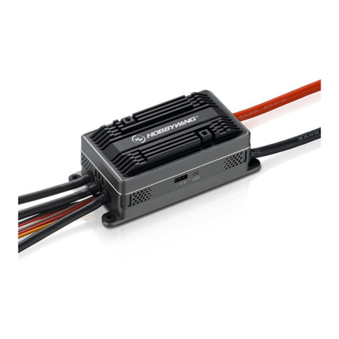
PLATINUM-260A-HV-SBEC-V5
PLATINUM-260A-HV-OPTO-V5
Brushless Electronic Speed Controller
PLATINUM 260A HV SBEC V5
Motor
Battery
Battery
OTA Module
1. Wiring diagram
1. The connection diagram
