01
Features
02
Begin to Use a New ESC
Connections
Specifications
CAUTIONS
CAUTIONS
ATTENTION
Thanks for purchasing the “SEAKING” series of Electronic Speed Controller (ESC) for RC boats.
High power system for RC models can be very dangerous, so please read this manual carefully.
Because we have no control over the use, installation or maintenance of the speed controller or
other related electronics, no liability may be assumed nor will be accepted for any damages, losses or
costs resulting from the use of this product. Any claims arising from the operation, malfunction and
others will be denied. We assume no liability for personal injury, consequential damages resulting
from our product or workmanship. As far as is legally permitted, the obligation to compensate is
restricted to the invoice amount of the affected product.
ATTENTION
ATTENTION
1
05
Multiple Protections
07
Trouble Shooting
Trouble(s) Solution(s)Possible Causes
No battery voltage is inputted to the ESC or got the polarity reversed.
The battery voltage is abnormal; or the startup temperature of the ESC is above 80°C.
Wrongly connected the ESC and motor wires.
The ESC is not set to “Forward and Backward” running mode;
The ESC cannot recognize the throttle neutral point.
The Low-Voltage Cutoff Protection or the Overheat Protection is activated.
The ESC and motor wire are not well connected or the ESC / motor is damaged
Check the connection between the battery and ESC, please re-solder if poor soldering exists. If the
polarity is reversed, please cut off the power immediately. Otherwise, the ESC will be damaged irreversibly.
Check the battery voltage; Check whether the water cooling system runs smoothly or not, or change
another ESC with greater amperage capability.
Swap any two wires connections between the ESC and the motor.
Set the running mode to “Forward and Backward”; recalibrate the throttle range according to
instructions in the section of "Throttle Range Calibration"
Replace another fully-charged battery; Cool the ESC down before using it again.
Check all the connections; replace the ESC or the motor. (Note: please test with a small throttle value first,
then increase the value after the motor returns to normal. Otherwise, the ESC/motor may get damaged again.
After powered on, the motor doesn’t work, but the following alert tone is
emitted: “beep-beep-, beep-beep-” (here the time interval is 1 second).
Pulling the throttle trigger, while the boat goes backward.
After powered on, the motor doesn’t emit any beep tone and the LED
doesn’t light up.
The boat cannot run backward.
The motor cannot be started normally, and it only stutters.
The power suddenly weakens in the motor rotating.
For safety, please always keep the
propeller away from human body or
any other objects.
Red color input wire is positive pole,
Black color input wire is negative
pole.
Model
SEAKING-30A-V3
SEAKING-60A-V3
SEAKING-120A-V3
SEAKING-180A-V3
SEAKING-130A-HV-V3
2-3 Not Available
Available
Available
Available
Available
2-3
2-6
2-6
30A
60A
120A
180A
130A
180A
360A
720A
1080A
720A
6V/1A
6V/2A
6V/5A
6V/5A
5-12
Boat ApplicableLiPo (S)
54.5x28.3x18.7mm
60.5x38.5x25.6
68.5x39.4x32
72x48x36.6
88x58x23
Size (incl. the
Water Cooling Pipe)
Continuous Peak Current Water Cooling Pipe
Inside/Outside
41g
93g
150g
207g
182g
Weight
External
Programming Port
BEC Type BEC Output
ATTENTION
Users need to recalibrate the throttle range when
using a new ESC or a used transmitter with some
of its settings have been changed like the
Throttle Trim, D/R, EPA or other parameters.);
otherwise the ECS cannot work properly.
2. If you are using a pistol transmitter:
a) Pull the throttle trigger to the top forward position (/full throttle), connect the ESC to the battery pack, then turn the
switch on; 2 seconds later, a row of “Beep- Beep-” can be heard, that means the full throttle position has been confirmed.
b) Release the throttle trigger to the neutral position, a steady and long “Beep—” can be heard, that means the neutral
position has been confirmed.
3. If you are using a stick transmitter:
a) Push the throttle stick to the top position (/full throttle), connect the ESC to the battery pack, then turn the switch on; 2 seconds later,
a row of “Beep- Beep-” tone can be heard, that means the full throttle position has been confirmed.
b) If you want to set it (/the throttle range) to half-range, please move the throttle stick to the neutral position, a steady and long “Beep—”
can be heard, that means the neutral position has been confirmed.
If you want to set it to full-range (In such a case, the boat cannot run backward), please pull the throttle stick to the bottom position
(/full brake), a steady and long “Beep—” can be heard, that means the bottom position has been confirmed.
Note: When the motor
emits “Beep” tone(s),
the red LED in the ESC
flashes at the same
time.
Note: When the
motor emits
“Beep” tone(s), the
red LED in the ESC
blinks at the same
time.
IMPORTANT
1. Turn on the transmitter, set parameters on the throttle channel like “D/R”, “EPA” and “ATL” to 100% (for transmitter without LCD, please turn the knob
to the maximum) and the throttle “TRIM” to 0 (for transmitter without LCD, please turn the corresponding knob to the neutral position). For Futaba
TM
radio
transmitter and similar ones, the direction of throttle channel shall be set to “REV”, while other radio systems shall be set to “NOR”. We strongly
recommend activating the “Fail Save” function of the radio system and set it (F/S) to “Output OFF” or set its value to the “Neutral Position” to ensure the
boat can be stopped when there is no signal received from the transmitter. Note: if the transmitter has the ABS brake function, please disable it.
Connect the ESC, motor, receiver, battery and servo according to the wiring diagram below (Picture 1/2). Three wires from the ESC to the motor have no polarity, so you can connect them freely. Please recheck all the connections and
ensure they are correctly connected before proceeding to step 2. (And you may find it’s necessary to swap two wires if the motor runs in reverse.)
1) Picture 1 is for Seaking-30A-V3, Seaking-60A-V3 and other ESCs that work with one LiPo battery pack; that is a wiring diagram with 1 battery pack.
2) Picture 2 is for Seaking-120A-V3, Seaking-180A-V3, Seaking-130A-HV-V3 and other ESCs that may work with two LiPo battery packs; that is the wiring diagram with 2 battery packs.
The Normal Start Process
1. Move the throttle stick to the bottom position (/full brake), then turn on the transmitter.
2. Connect the battery pack to the ESC, the turn the switch on.
3. The motor emits several “Beeps” to denote the cells number in your Lipo battery pack. Please make sure that the number is correct. If only one “Beep” tone is emitted, that means the “Low-voltage Cutoff
Threshold” (Please refer to the “Programmable Items” in the following form) is set to “No protection”, and it’s only suitable when you are using a NiMH/NiCd battery pack. Please never use the “No protection”
mode for Lipo battery; otherwise the Lipo battery will be damaged irreversibly.
4. One second later, the motor emits a steady and long “beep—” to confirm the zero-speed position of the throttle. If the throttle is not at that position, the motor will emit the continuous “beep-beep-beep...” till
the throttle returns to the zero-speed position.
5. Move the throttle stick upwards, the motor starts spinning and speeds up gradually.
03
Programmable Items
04
Program the ESC
1. Running Mode:
With the “Forward Only” mode, the boat can only go forward; while in
the “Forward and Backward” mode, the boat can go forward and reverse, which is
suitable for some specially-designed boats. Please read the user manual of your boat to
check if it can run backward.
2. Lipo Cells:
We strongly suggest setting the “Lipo Cells” item manually. If you choose the
“Auto Calculate”, the ESC will measure the battery voltage the moment it is connected to
the controller, then the ESC counts the cells number. For example, if the battery voltage is
lower than 8.8V, it will be identified as 2 cells Lipo battery. In order to ensure the ESC
calculate the cells number correctly, please always use a fully charged battery to connect
the ESC. If the battery is not fully charged or partly discharged, then the “Auto Calculate”
may get a wrong result.
Hint:
In the startup process, the motor will emit several “Beeps” to
indicate the Lipo cells number; it is helpful for you to check if it is consistent with the
actual cells number in your battery pack. If you often use Lipo battery packs with the fixed
number of cells, then we strongly suggest you to set the “Lipo Cells” to a fixed value
instead of using the “Auto Calculate”, as this can ensure the low-voltage cutoff protection
works normally all the time.
STEP 2. Select programmable items
After entered the programming mode, you will hear the following 4
kinds of “Beep” tones circularly. If move the throttle stick to the
bottom position (/full brake) within 3 seconds after one kind of “Beep”
tone emits, then the corresponding item will be selected.
1. “Beep-”, Running Mode (1 short “beep”)
2. “Beep-Beep-”, Lipo Cells (2 short “beeps”)
3. “Beep-Beep-Beep-”, Low-voltage Cutoff Threshold (3 short “beeps”)
4. “Beep-Beep-Beep-Beep”,Timing (4 short “beeps”)
Program card is an optional equipment for boat ESCs, it has 3 digital LEDs to display the programmable items and corresponding parameter values, so the user interface is very intuitive. The SEAKING-30A-V3 ESC uses the throttle
cable to connect to LED Program Card, while other SEAKING V3 ESCs use the External Programming Ports to connect LED Program Card.
“Beep- Beep-” “Beep—”
ATTENTION
“Beep- Beep-” “Beep—”
1 2 3 4 5 6 7 8
1. Running Mode Forward Only
Forward and
Backward
2. Lipo Cells
Note1 Auto Calculate
2cells 3cells 4cells 5cells 6cells
Note2 Auto Calculate
5cells 6cells 8cells 10cells 12cells
3. Low-voltage Cutoff
Threshold No Protection 2.8V/Cell 3.0V/Cell
3.2V/Cell
3.4V/Cell
4. Timing 0.00° 3.75° 7.50° 11.25°
15.00°
18.75° 22.50° 26.25°
Options
Programmable Items
• The water-proof level of the “SEAKING V3” series has reached IP67, indicating the speed controllers can operate
in water and users can directly use them without taking any precaution measures. (Note: please fully dry all the
connectors after use for avoiding rustiness.)
• The Copper Bar Heat Conduction technology (exclusively patented), water-cooling system and MOSFET with
extremely low internal resistance, all these greatly upgrade the over-current withstanding capability and
reliability of the speed controllers.
• Brand-new software specially designed for RC boats, featured by excellent start-up & acceleration performance.
In addition, it has outstanding adaptability to sudden load change caused by the hull bumping in sailing.
• 2 running modes: “Forward Only” and “Forward and Backward” for different applications.
• Multiple protections like low-voltage cutoff protection, over-heat protection and throttle signal loss protection,
those features specially designed for RC boats are reasonable and personalized.
• 8 options for timing adjustments, compatible with most kinds of sensorless brushless motors.
• Pocket-sized program card can help users to set the speed controller easily. (Note: The program card is optional)
Throttle Range Calibration
2
Program the ESC with your transmitter
1
Program the ESC with a Program Card
2
Linear Mode
Linear Mode
Switch Mode
Switch Mode
Without BEC
Length<45cm
Length<70cm
Length<110cm
Length<130cm
Length<150cm
The italics in the following form are the default settings.
Note1: Parameters in this line are available for normal voltage ESCs (work with 2-6S LiPo)
Note2: Parameters in this line are available for high voltage ESCs (work with 5-12S LiPo)
3. Low-voltage Cutoff Threshold:
This function prevents the Lipo battery pack from over-discharging. The ESC detects the battery voltage all the time, if the voltage goes below the threshold for 2 seconds, the output power will be halved
and the Red LED flashes slowly, then please replace the battery pack as soon as possible.
a) Warning!
If you ignore the low voltage cutoff warning and keep running, the Lipo battery will be damaged irreversibly!
b)
How to calculate the cutoff threshold of a battery pack:
The cutoff threshold of a battery pack = the threshold of each cell x cells number
For example, if the threshold of each cell is set to “3.2V/Cell”, and the battery pack is a 3S (3 Cells), then the cutoff threshold of this battery pack is 3.2x3=9.6V.
C)
If you are using a NiMH or NiCd battery:
NiMH and NiCd batteries are not easy to be damaged, so you needn’t worry about the over-discharging problem, you can set this programmable item to “No Protection”.
4. Timing:
Please select the most suitable timing option according to the motor you are using. The correct timing makes the motor run smoothly. Generally speaking, higher timing brings out higher output power, higher speed and also higher
temperature.
By 4 Steps: Enter the programming mode →Select programmable item(s) →Choose a new value for the selected item →Exit
“B”
1 short Beep
Tone
Items
“BB”
2 short Beeps
“BBB”
3 short Beeps
“BBBB” 4
short Beeps
“Beep—”
1 long
Beep
“Beep—B”
1 long+
1 short
“Beep—BB”
1 long+
2 short
“Beep—BBB”
1 long+
3 short
Running Mode Fwd. Only
Auto Calculate
Fwd. & Bwd.
Lipo Cells 2Cells 3Cells 4Cells 5Cells 6Cells
Low-voltage
Cutoff Threshold No Protection 2.8V/Cell 3.0V/Cell 3.2V/Cell 3.4V/Cell
Timing 0.00° 3.75° 7.50° 11.25° 15.00° 18.75° 22.50° 26.25°
1. Low Voltage Cutoff Protection:
when the battery voltage falls below the preset cutoff threshold for over 1 second, the ESC will cut off the output and stop working, then the Red LED blinks slowly. The controller can be reoperated at the
halved power after the throttle returns to zero.
2. Overheat Protection:
when the ESC temperature goes above the factory preset value, the ESC will cut off the output and stop running, then the Green LED flashes slowly. The controller can be reoperated at the halved power after the
throttle returns to zero, the output will resume if the temperature decreases below 80°C.
3. Throttle Signal Loss Protection:
when the receiver detects no throttle signal (from the transmitter) for over 0.1 second, the ESC will cut off the output. The controller will not resume running until the signal is detected again. Hereby, we
suggest users setting the no signal protection (or F/S protection value) on the TH channel (on the transmitter) to “Output off” or “Neutral position”.
06
LED Indications
There are two LED indicators in the ESC,a Green one and a Red one.
1. When the throttle is above the zero speed position, the Red LED will come on and the motor starts to spin; while pushing the throttle to the maximum position (/ full throttle), the motor runs at its full speed and both the Red & Green LEDs
light up.
2. When setting the throttle range and parameters of the ESC, the motor beeps and Red LED flashes simultaneously for easy observation.
3. Green LED blinks slowly denoting the ESC has entered the overheat protection, Red LED flashes slowly means the Low-Voltage Cutoff Protection is activated.
Picture 1 Picture 2
Battery
Motor
Receiver
Switch
Blue
Yellow
Orange
Electronic Speed Controller
Battery
Battery
Switch
Motor
Receiver
Electronic Speed Controller
Blue
Yellow
Orange
STEP 1. Enter the programming mode
1. Switch on the transmitter, move the throttle stick to the top position
(/full throttle), and then connect the battery pack to the ESC.
2. Turn on the ESC, wait for 2 seconds, the motor emits “Beep-Beep-”
tone.
3. Wait for 5 more seconds, the motor emits a special tone “♪56712”,
that means the controller enters the programming mode.
• •
STEP 3. Choose a new value for the selected item
After entered a certain item, the motor will beep in a loop. Set the corresponding value by moving the throttle stick to the top position (/full
throttle) when you hear the tone, then a special tone “♪1515 ” emits, which means the value has been chosen and saved into the ESC. (If keep
the throttle stick at the top position (/full throttle) for over 2 seconds, you can return to STEP 2 and set other items; if move the stick to the
bottom position (/full brake) within 2 seconds, then you will exit this programming mode directly.)
• •
STEP 4. Exit the programming mode
There are 2 methods to exit the programming mode:
1. In STEP 3, the motor emits the special tone “♪1515” after chosen the value, at this moment user can move the throttle stick to the bottom
position (/full brake) in 2 seconds to exit the programming mode.
2. Disconnect the battery pack from the ESC to exit the programming mode forcibly.
• •
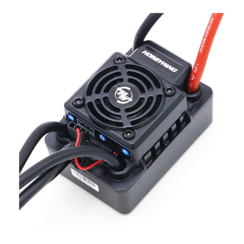
USER MANUAL
30A • 60A • 120A • 180A • 130A-HV
Brushless Electronic Speed Controller
Ф2.0/4.0 mm
Ф2.0/4.0 mm
Ф3.0/5.4 mm
Ф3.0/5.4 mm
Ф3.6/5.0 mm
