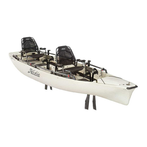
Hobie Wave User manual
Other Hobie Boat manuals

Hobie
Hobie Float Cat 75 Installation and operating instructions

Hobie
Hobie QUEST User manual

Hobie
Hobie Gateway User manual
Hobie
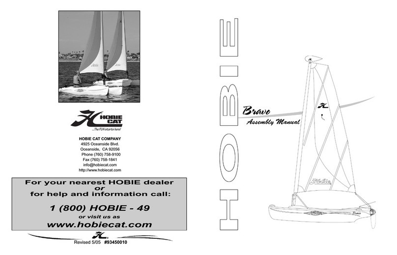
Hobie Bravo User manual

Hobie
Hobie mirage Pro Angler User manual

Hobie
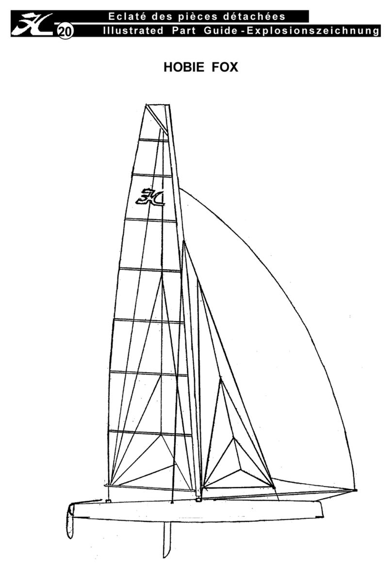
Hobie Mirage Pro Angler User manual
Hobie
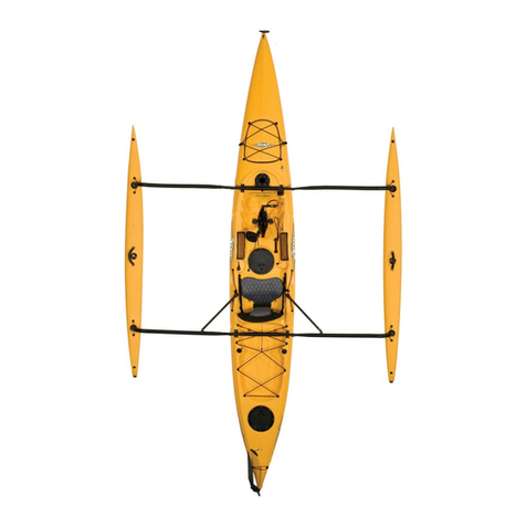
Hobie FOX User manual
Hobie
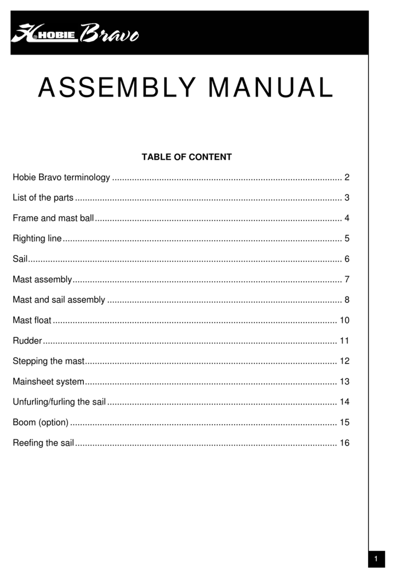
Hobie Mirage Drive Manual

Hobie
Hobie 15 User manual
Hobie
Hobie Brave User manual

Hobie
Hobie PEARL User manual
Hobie
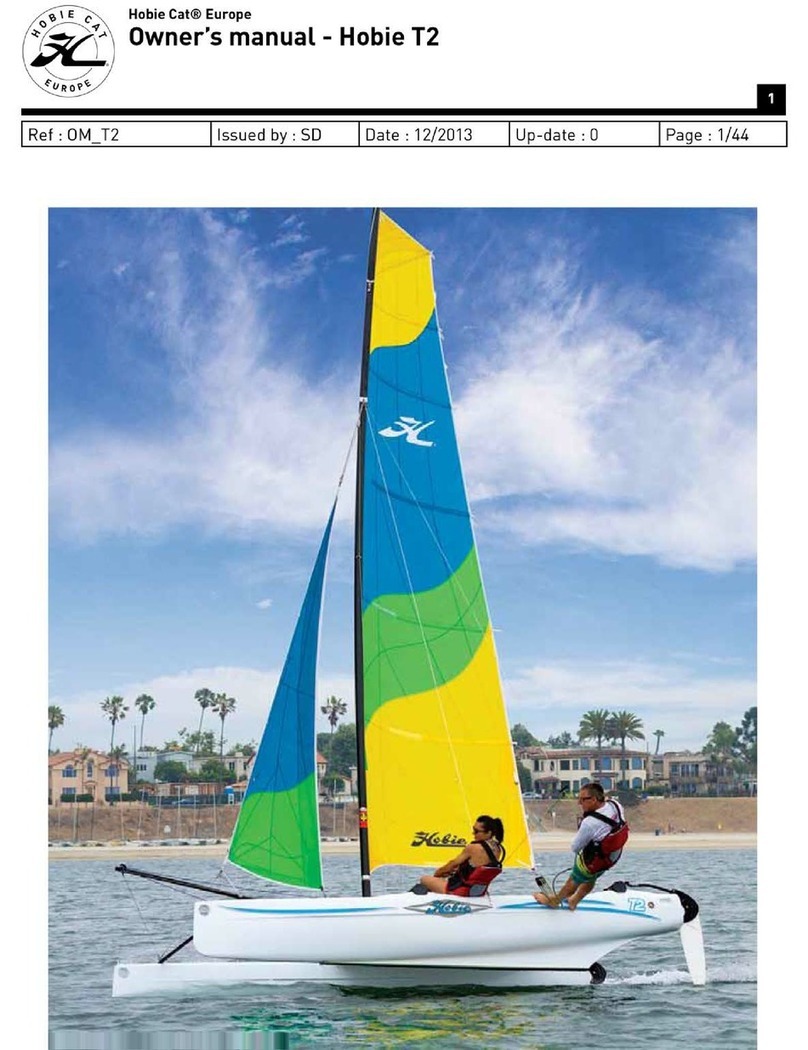
Hobie Hobie T2 User manual
Hobie
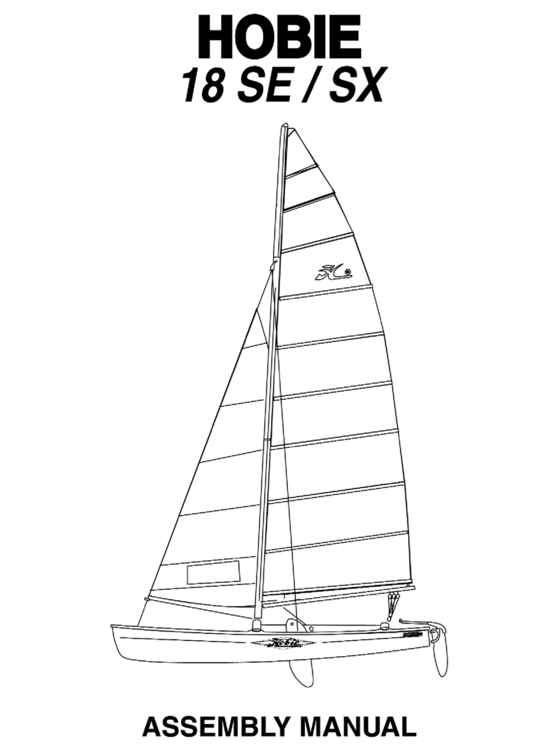
Hobie 18 SX User manual
Hobie
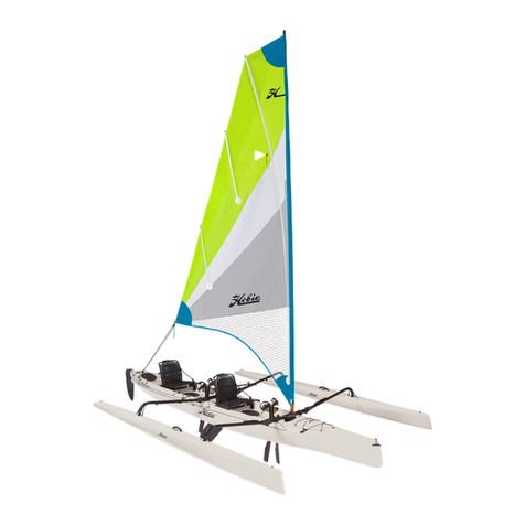
Hobie Mirage Tandem Island User manual
Hobie
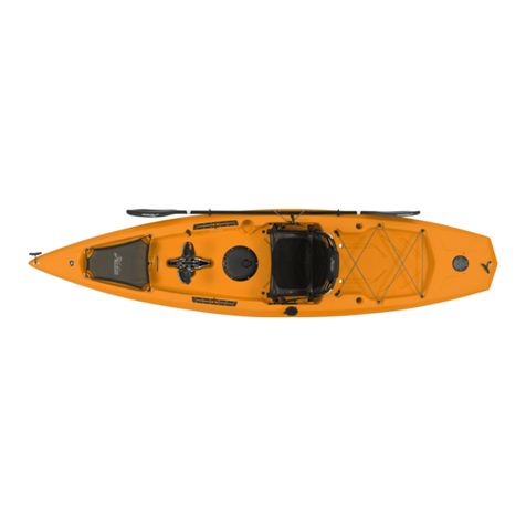
Hobie Mirage Compass User manual
Hobie
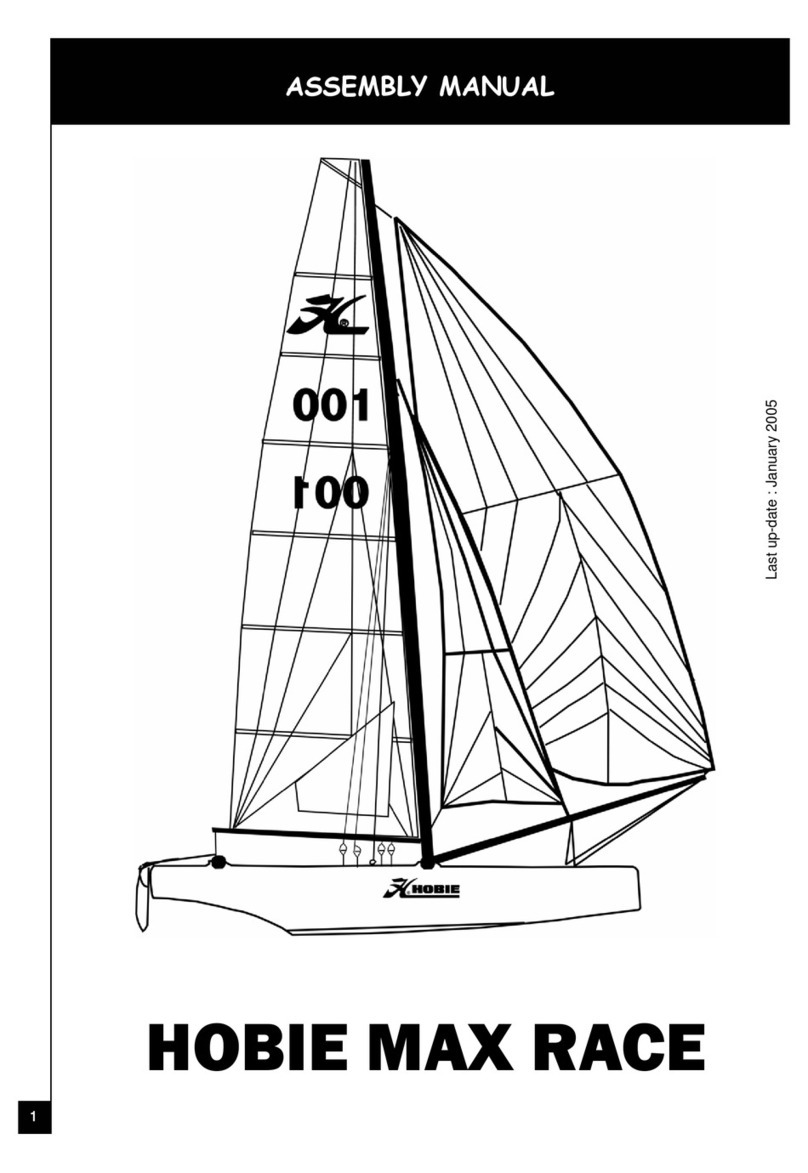
Hobie MAX RACE User manual
Hobie
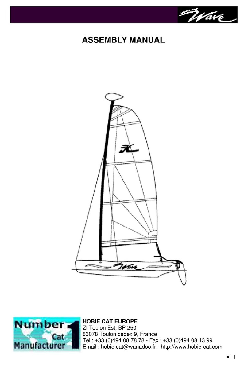
Hobie Wave User manual
Hobie
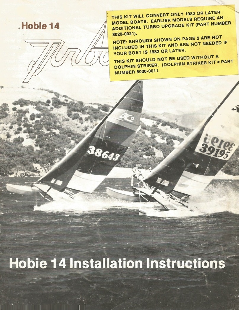
Hobie 14 Turbo User manual
Hobie
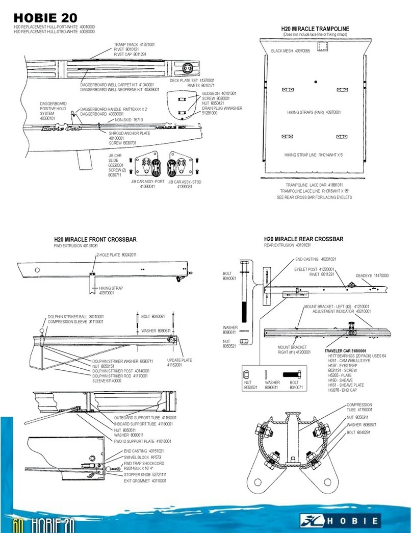
Hobie HOBIE Miracle 20 User manual
Hobie
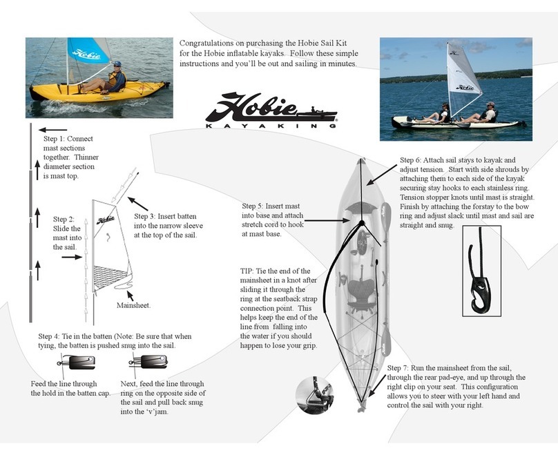
Hobie Mirage Inflatables User manual
Popular Boat manuals by other brands

Jeanneau
Jeanneau SUN ODYSSEY 41 DS owner's manual

Meridian
Meridian 490 Pilothouse owner's manual

Advanced Elements
Advanced Elements AdvancedFrame Expedition AE1009 owner's manual

Robo Marine Indonesia
Robo Marine Indonesia GEOMAR user manual

Swallow Boats
Swallow Boats BayRaider owner's manual

X SHORE
X SHORE EELEX 8000 owner's manual
