Hoffmann MORSO User manual

© Hoffmann Machine Company, Inc.
OPERATING MANUAL
for
MORSO manual notching machine
Model NFL
Hoffmann Machine Company, Inc.
1386 Drexel Road Valdese, NC 28690 USA
Phone: (828) 430 - 4510 Fax: (828) 430 –4620
e-mail: info@Hoffmann-USA.com
www.Hoffmann-USA.com
Toll-free Technical Support: (866) 248 –0100

Instructions Manual
MORSØ
Notch Cutting Machine
Model NF
CONTENTS
0
-
1
Introduction page A-1
Work Piece
Shortening of the work piece on
a circular saw before cutting page B-1
Functional Description
general description page C-1
machine description page C-2
description of the
lever system page C-3
Technical Data page D-1
Mounting Instructions
general page E-1
mounting of table extensions
and fences page E-1
Operating Instructions
before starting page F-1
adjustment of cock-bead stops page F-2
adjustment of centre stop page F-3
adjustment of flip stops page F-4
adjustment of height stop page F-5
Cutting of bars with rebate
Description page G-1
Service References
lubrication instructions page H-1
cleaning page H-1
changing of knives and chip
breakers - adjustment page H-2
grinding of knives page H-3
regulation of draw bar page H-4
adjustment of springs page H-5
changing of spare parts page H-6
Locating Faults / Methods for Repair page I-1
Safety
safety devices page J-1
regulations page J-1
Index of Spare parts
survey page K-1
machine page K-2
knife block unit page K-3
drive mechanism page K-4

Instructions Manual
MORSØ
Notch Cutting Machine
Model NF
INTRODUC
TION
A
-
1
We recommend to read this instruction manual
carefully before the first starting of the machine.
Defects on the machine provably arisen due to
mistakes in operation will not be covered by the
warranty.
Use of the Instruction Manual:
In this instruction manual all information needed
for using all possibilities of the MORSØ notch
cutting machine is found.
(see picture A-1-1)
(1) Head Lines
Refers to the head line of the chapter.
(2) Index of pages
The letter is the description of the chapter.
The figure is the consecutive page number in the
chapter.
(3) Text
The texts belonging to the chapter in which you
will find all information and explanations
necessary.
(4) Illustration
Drawing to the text in (3).
Picture A-1-1

Instructions Manual
MORSØ
Notch Cutting Machine
Model NF
WORK PIECE
B
-
1
Shortening of work piece on a circular saw
before cutting
Before the cutting of the work piece it must be
shortened in the correct length on a circular saw.
It is very important that the saw blade is exactly
adjusted in 90°proportional to the machine table
(see fig. 1). The blade must also be exactly
adjusted in 90°proportional to the fence (see fig.
2).
Fig. 1
If this adjustment is not correct on there will be a
gap in the finished joints.
Fig. 2

Instructions Manual
MORSØ
Notch Cutting Machine
Model NF
FUNCTIONAL DESCRIPTION C
-
1
General Description
MORSØ-NF notch cutting machine is an important
help to cut window bars, mullions, and cabinet
front frames requiring haunch joints.
MORSØ-NF is a manual foot-operated machine.
The operation is easy.
MORSØ-NF notch cutting machine is provided
with 6 sliding longitudinal stops, fences (1500 mm)
on both the right and left side of the machine,
nose knives, side knives, chip-breaker, cock-bead
stops, centre stop, safety guard, and waste chute.
With the MORSØ-NF you achieve a quite smooth,
clean, and exact cut by cutting the work piece in
two cuts.
This is done manually on the MORSØ-NF.
The conveying (forward movement) of the knife
block is continuously adjustable.
A
special lever system makes the operation of the
machine very easy. Twin return springs bring the
knife block back to starting position.
The height movement of the knife block (length of
stroke) is continuously adjustable.
The work pieces can be joined without any
finishing.

Instructions Manual
MORSØ
Notch Cutting Machine
Model NF
FUNCTIONAL DESCRIPTION C
-
2
Machine Description
The MORSØ-NF is constructed as a compact
machine with a solid dimensioned frame (1), with
built in lever system (2).
The cutting function (3) is placed on top of the
machine.
In the slide frame (4) fitted at the cross (5) the
knife block (6) is moved up and down. The cross
(5) runs in the guidings of the table.
The knives (7) fitted on the knife block cut the
mullion.
The conveying (forward movement) of the knife
block takes place manually.
The mullion is placed on the table (8) against the
fences (9).
The cock-bead stops (11) are adjusted to the
required cutting depth.
The adjustment of the sliding longitudinal stops
(12) is done by means of a template of the
mullion.
MORSØ-NLF can be fitted with nose knives from
12 to 26 mm.
MORSØ-NSF can be fitted with nose knives from
6 to 20 mm.

Instructions Manual
MORSØ
Notch Cutting Machine
Model NF
FUNCTIONAL DESCRIPTION C
-
3
Description of the Lever System
The cutting movement is carried out manually.
The length of stroke of the knives is adjusted to
max. 165 mm.
The cutting takes place by means of a foot
operated lever system.
The pedal (1) is pressed down.
The foot pedal tipper (2) pulls the draw bow (3),
draw bar (4), and the knife block (5) down.
By relieving the foot pressure from the foot pedal
the knife block returns to top position by means of
the two springs (6).
The height stop (7) is slidable.

Instructions Manual
MORSØ
Notch Cutting Machine
Model NF
T
ECHNICAL DATA D
-
1
Machine Dimensions (max.):
Length (a) : 3700 mm
Width (b) : 510 mm
Height (c) : 1150 mm
Weight : 96 kg
Placing Measures:
Spaciousness to Wall
min. : 1000 mm
Noise/Pollution:
Noise Level : noiseless
Pollution : none/no dust
Working Capacity:
Nose widths (NSF) : 6 - 20 mm
Nose widths (NLF) : 12 - 26 mm
Working Width (max.) : 70 mm
Working Height (max.) : 160 mm
Extension tables
(left and right) : 1000 mm
Fences (right and left) : 1500 mm

Instructions Manual
MORSØ
Notch Cutting Machine
Model NF
MOUNTING INSTRUCTIONS E
-
1
In General
The machine is delivered ready for start and
complete with standard equipment.
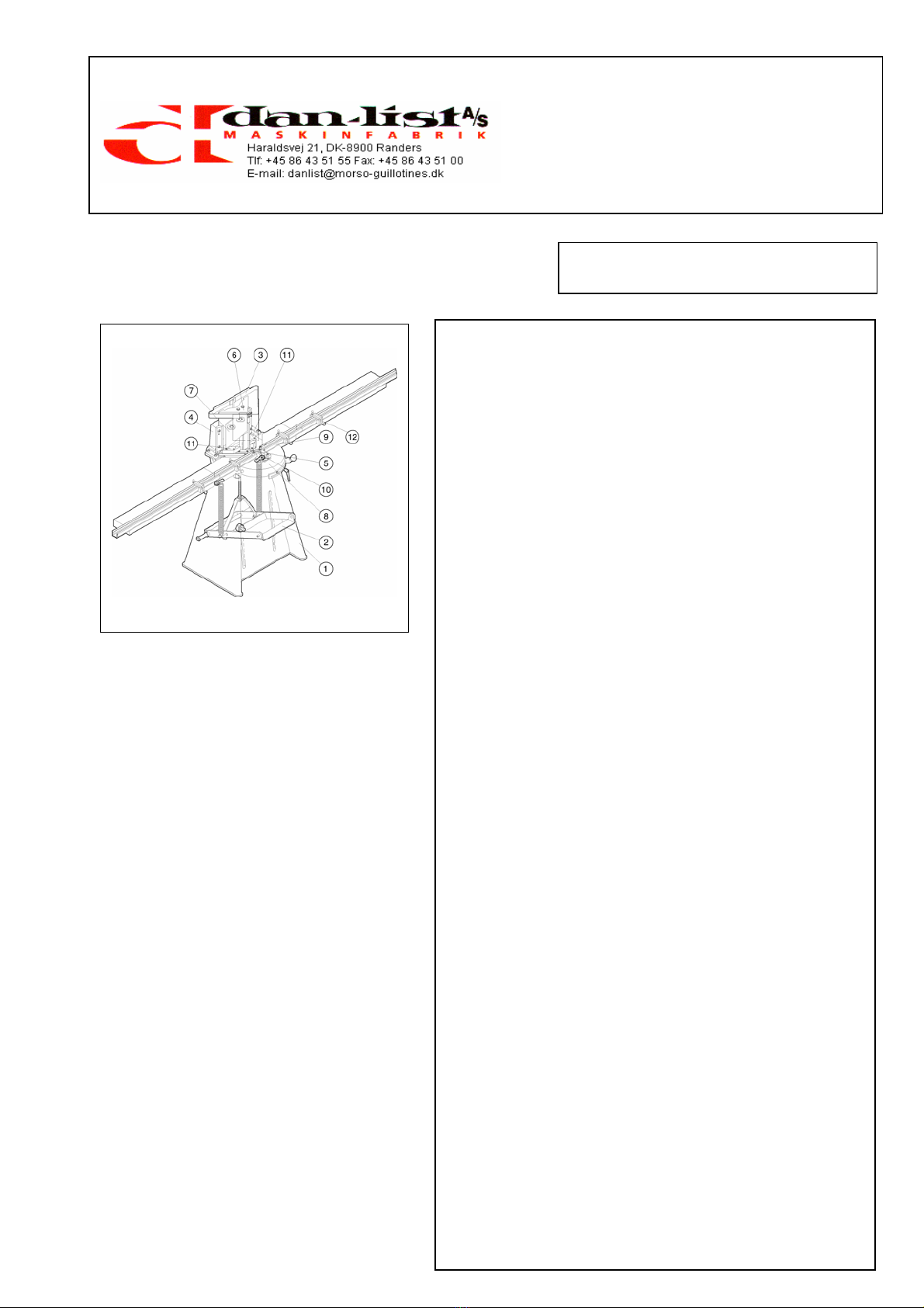
Only the table extensions (1) and fences (2) are
dismounted during transport.
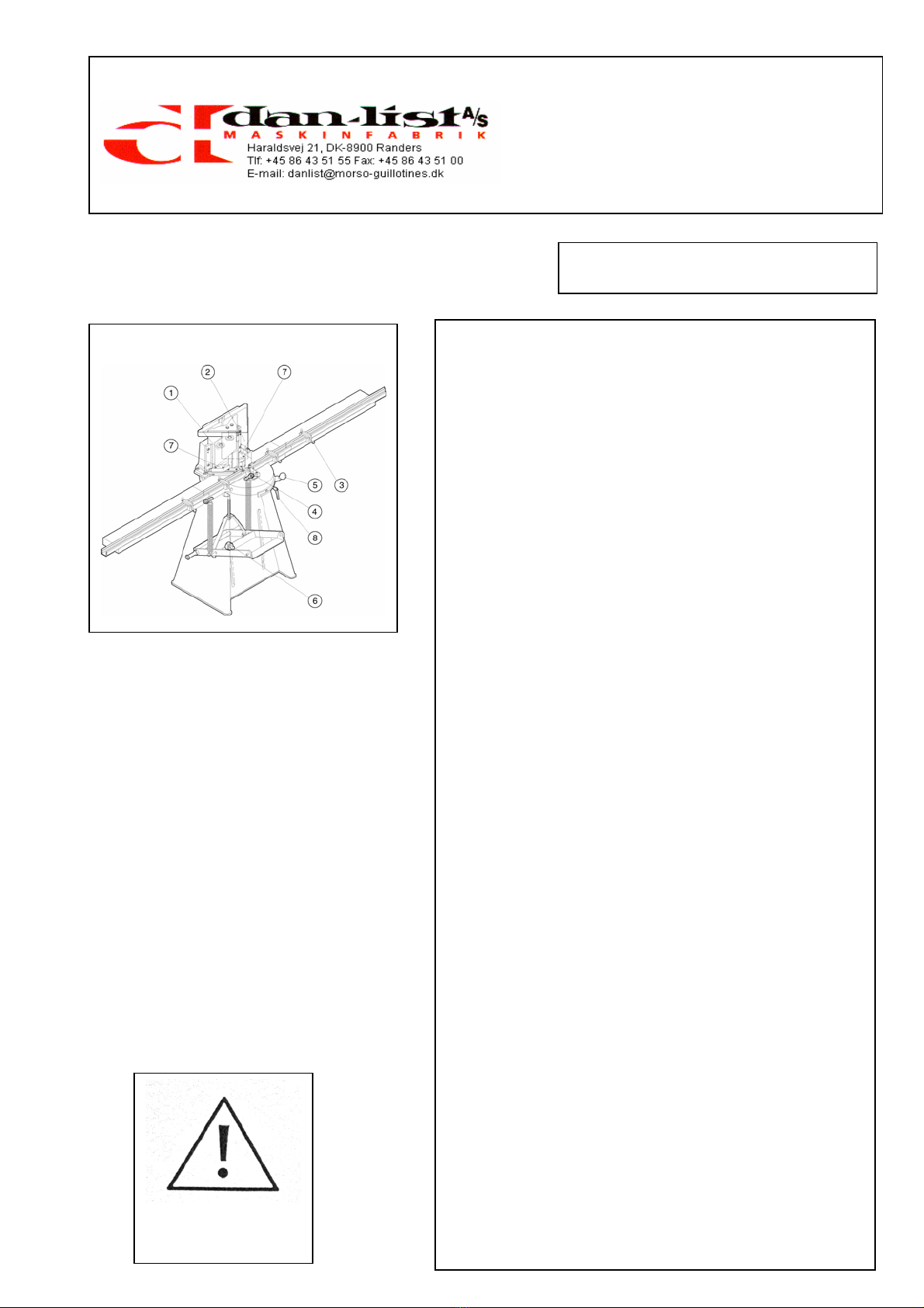
NOTE before starting up first time:
1. The handle on the tooth arc is loosened (it
functions as the rear stop when moving the
knife block backwards).
2. The knife block is moved halfway backwards,
and the waste chute is fitted.
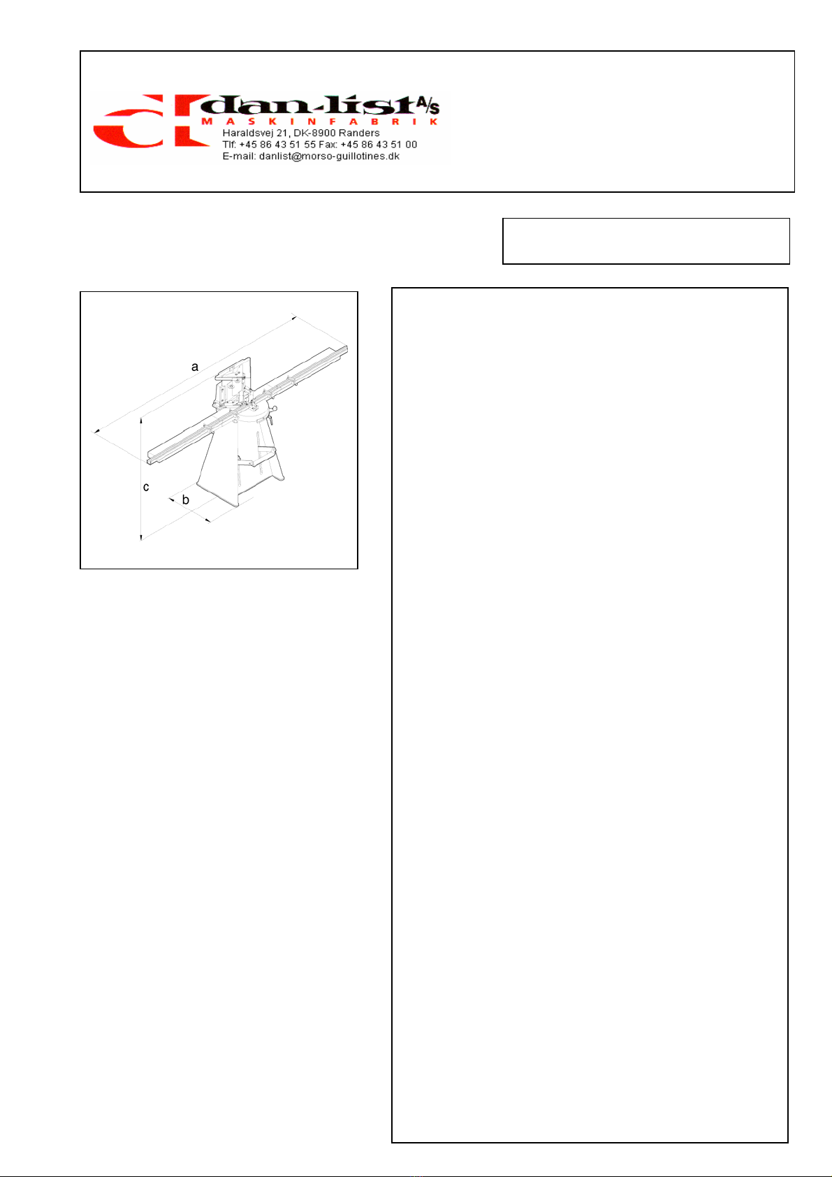
Placing according to the spaciousness to wall
stated in D-1. The machine can be fastened to the
floor with screws in the two holes in the bottom of
the machine frame.
Check before each start that all protection
devices are fitted correctly.
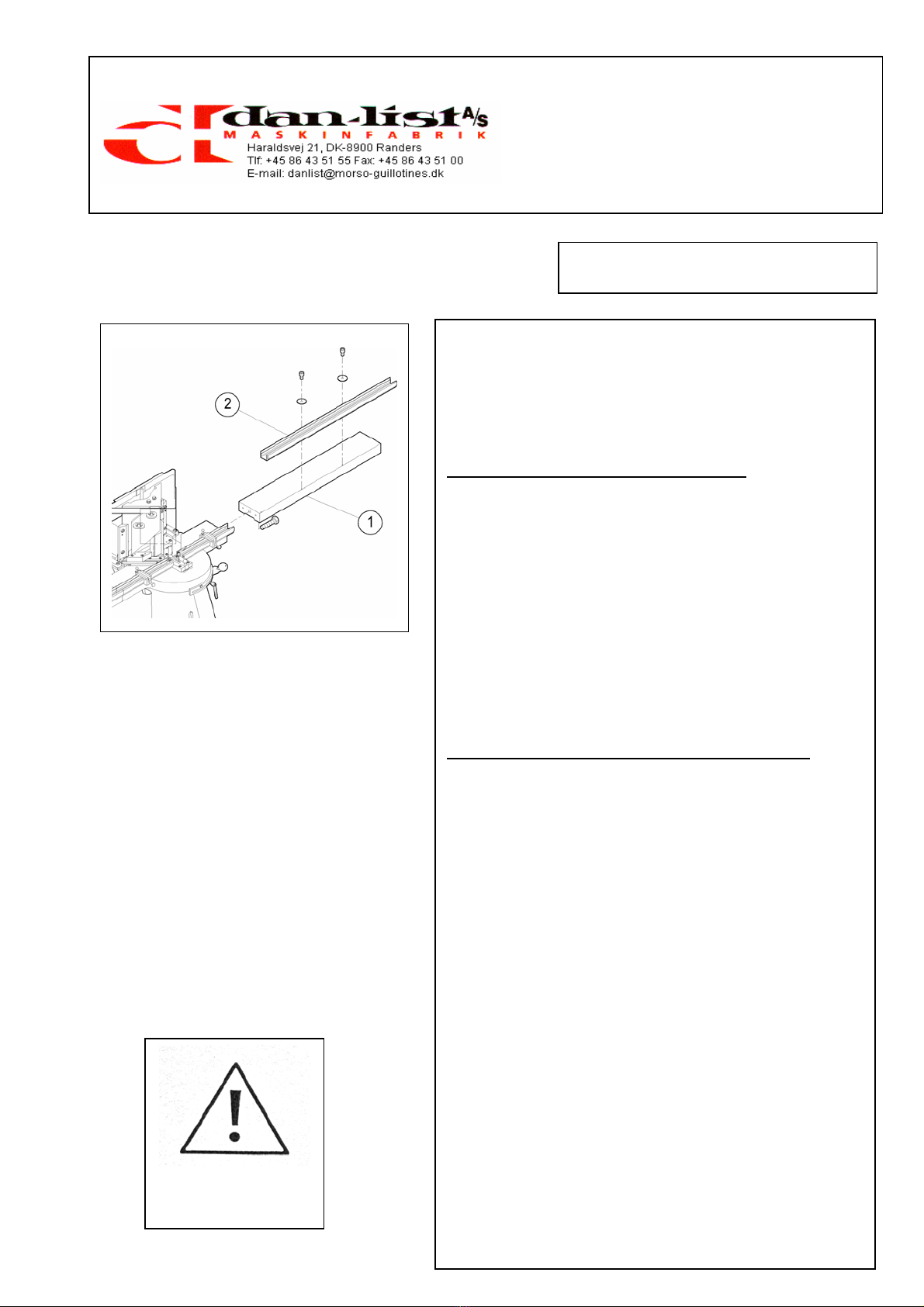
Fitting of the Table Extension and fences
(on the drawing the right side is shown, the same
procedure on the left side).
Before fitting the table extension (1) the ends of
the table extension and the table must be cleaned
very thoroughly. Special attention must be paid to
the pin and screw holes, as the smallest amount
of dirt will prevent the correct alignment.
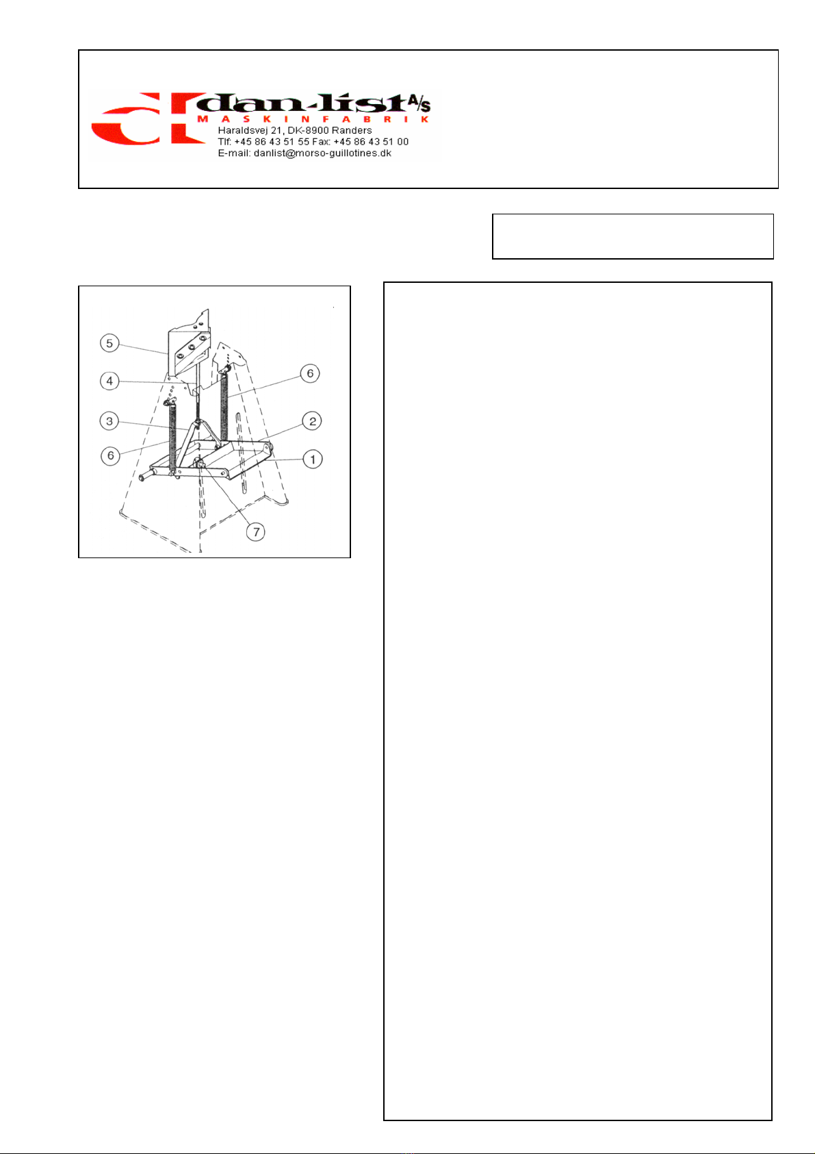
After the cleaning, the table extension is pressed
against the table so that the pins placed in the
table extension are inserted in the pin holes in the
table. The included screw is now inserted in the
screw hole and fastened with a standard screw
driver.
The fence (2) is fitted on the table extension (pins
are fitted in the table extension). It is fastened with
cylinder screw.
(Extra extension table and supporting leg can be
delivered as accessories).
BEWARE OF THE
EXTREME SHARP
KNIVES

Instructions Manual
MORSØ
Notch Cutting Machine
Model NF
OPERATING INSTRUCTIONS F
-
1
Before Starting
Before starting the machine the following must be
checked and adjusted:
1. Check
a) knives (1)
general condition
sharpness
b) waste
room for waste
c) safety devices
fitting of all safety devices:
safety guard for knives (2)
d) table and table extension
cleanness and undamaged surface
2. Adjustments
a) Cock-bead stops (7)
(adjustment instructions page F-2)
b) centre stop (4)
(adjustment instructions page F-3)
c) sliding longitudinal stops (3)
(adjustment instructions page F-4)
d) height stop (6)
(adjustment instructions page F-5)
f) Rear Stop (8)
BEWARE OF THE
EXTREME SHARP
KNIVES

Instructions Manual
MORSØ
Notch Cutting Machine
Model NF
OPERATING INSTRUCTIONS F
-
2
Adjustment of the cock-bead stops
The cock-bead stops (1) are adjusted as follows:
1. Loosen the Allen screws on the cock-bead
stops (1) and move these to rear of the sliding
guide.
2. Using a test piece (2) make a notch cut into
the cock-bead. This cut must be the same
depth as the cock-bead. The overall width
must be equal to the width of the centre cross-
rail. When you are satisfied the two sizes are
equal, we can now position the cock-bead
stops (1).
3. Press the foot-pedal down and hold it in this
position. By operating the hand lever, bring the
knife block (3) forward into the previously cut
notch. Position the cock-bead stops (1)
against the cock-bead and lock them in place
using the Allen screws. When these stops are
fixed in position the knife block (3) can only cut
into the cock-bead as far as this setting. The
notch cut depth is then referenced from the
face of the cock-bead. The width of stile can
vary without changing this setting.
4. Check the alignment of the two cock-bead
stops (1) using a straight edge. By bringing the
knife block (3) forward, check that they are
level and true with the fence.
5. Lock the second Allen screws on the cock-
bead stops (1).
6. This setting will allow you to make regularly
accurate notch cuts in the stiles. These stops
will need no further adjustment unless the size
of the cock-bead changes.
BEWARE OF THE
EXTREME SHARP
KNIVES

Instructions Manual
MORSØ
Notch Cutting Machine
Model NF
OPERATING INSTRUCT
IONS F
-
3
Adjustment of the centre stop
The centre stop regulates the amount of material
cut from the corners of the cross-rails.
The centre stop is adjusted as follows:
1. The adjustment screws (1) are located in each
side of the Teflon head (3) on the centre stop
(2). They can be turned in or out, to allow
more or less material to be cut from the corner
of the cross-rail.
The adjustment screws (1) are adjusted
exactly equal on both sides so that the
distance from the screw head to the centre of
the Teflon piece (3) is equal
Example:
Nose width 12 mm:
The width of the Teflon piece (3) is measured.
The screws (1) are adjusted exactly equal on
both sides, so that the distance from the screw
head to the centre of the Teflon piece (3) is 6
mm.
2. You can make minor adjustments if the width
of the cross rail should vary (e.g. 11.9 or 12.2
mm instead of 12 mm). Make a 45°cut in a
test piece on the cross-rail and offer it up to
the notch cut already made in the test stile
(see page F-2). If there is a gap in either of the
two corners, adjustments can be made on the
screws until an exact and tight joint is
achieved.
3. To achieve this balance, take a test piece of
centre-rail and cut one corner (4). Turn the
centre-rail to the opposite side of the knife
block up-side-down so that you cut in the
same corner. Place it against the centre stop
and bring the cutting block partially through. If
this causes a fine cut or the knives do not
touch the centre-rail, the two screws are not
balanced with each other. The adjustment
screws are balanced until the cut is correct.
It is particularly important to get this balance,
when frames are made with single cock-beads
on top and bottom rails. If the two corners are
not taken off exactly equal, there will be a gap
on one corner and an over-tight joint on the
other. This will also produce frames that are
not square.
BEWARE OF THE
EXTREME SHARP
KNIVES

Instructions Manual
MORSØ
Notch Cutting Machine
Model NF
OPERATING INSTRUCTIONS F
-
4
Adjustment of the flip
-
stops
Making a Template
For setting the flip stop positions a template of the
stile (upright section) is made. Mark the centre of
the positions on the cross-rails, incl. the top and
bottom rails (see fig. 2) on the stile.
1. To make the template, put the stile in the
machine. For the top and bottom rails always
start cutting from the end of the stile. Feed the
section in by 5 mm at each cut (to prevent
break out along the end grain). See fig. 1
Fig. 1 2. When a few cuts have been made, align the
rail with the set mark and the centre line on
the nose knife (see fig. 2). Make a proper cut
in the position.
3. Bring the first stop forward against the end of
the template and lock it.
4. Flip this stop over and go to the next position
marked on the rail. Make the second cut and
bring the second stop to the same end of the
rail. Lock the stop in position. Continue the
procedure until all stops have been positioned
and set.
5. When setting the last stop, make a few 5 mm
cuts from the end and in (see fig. 1) (to pre-
vent break out) before setting the stop and
locking it.
Fig. 2 6. The same template is used to position the
stops on the other side. Place the template on
the other side of the knife block up-side-down
when setting the stops. Bring the cutting block
into the existing notch cut outs and position
each stop in turn – as described above.
BEWARE OF THE
EXTREME SHARP
KNIVES

Instructions Manual
MORSØ
Notch Cutting Machine
Model NF
OPERATING INSTRUCTIONS F
-
5
Adjustment of Height Stop
The height stop (1) is used for adjustment of the
knife block (2) to a suitable height compared to
the moulding to be cut.
In this way you avoid unnecessary high foot
movements.
The moulding is placed on the table (the knife
block must be in the rear position, as shown on
the picture). The knife block (2) is moved forward
to the front position by means of handle (3).
With the foot pedal (4) the knife block (2) is moved
down to the height required, yet min. 20 mm
above the moulding.
The height stop (1) is loosened the spanner.
Fasten the height stop against the foot pedal
tipper (5).
The height stop is also used for locking the knife
block in the bottom position when the machine is
not used.
BEWARE OF THE
EXTREME SHARP
KNIVES

Instructions Manual
MORSØ
Notch Cutting Machine
Model NF
CUTTING OF BARS G
-
1
Cutting of bars with rebate
With the MORSØ-NF machine it is also possible
to cut bars with rebate.
You must make support mouldings (1) and
support blocks (3) for the rebate in the bar. If
these devises are not used the rebate will splinter
during cutting. The support mouldings and support
blocks can be made out of hard wood or nylon.
IMPORTANT: The height of the support blocks (3)
must be approximately 1/10 mm lower that the
height of the rebate.
Use the following procedure:
1. The support mouldings (1) for the bar rebate is
fastened onto the fences (2) with screws.
2. The support blocks (3) are fastened on the
cock-bead stops (4) with screws.
All adjustments before cutting are the same as
described on pages F-1 to F-5.
The carving of the coggin takes place manually on
a circular saw or a spindle moulder.
BEWARE OF THE
EXTREME SHARP
KNIVES

Instructions Manual
MORSØ
Notch Cutting Machine
Model NF
SERVICE
H
-
1
Lubrication Instructions
Approx. every two weeks lubricate:
The guidings for
1. Knife block (1)
2. Slide Frame (2)
3. Cross (3) (lubricates simultaneously the
forward movement of the knife block).
4. Links for the draw bar (4) of the knife block.
5. All links in the lever system (5), incl. spring
suspension.
Lubricant: Any acid-free oil.
Cleaning
MORSØ-NF must be cleaned thoroughly after
use.
Remove any waste wood from all the guidings.
Remove the waste wood from behind the
machine.

Instructions Manual
MORSØ
Notch Cutting Machine
Model NF
SERVICE
H
-
2
Changing of Knives and Chip Breaker –
Adjustment
1. Knife Block (1) is placed in top position
2. The side knives (2) + (3) are dismounted by
loosening screws (6). The nose knife (4) is
dismounted by loosening screws (5).
TAKE CARE OF YOUR FINGERS.
3. Clean the surfaces of the knife block and the
new side knives (2) + (3) very carefully as
even the smallest impurity between side knife
and knife block can cause an incorrect cut.
4. The nose knife (4) that fits the width of the
cock-bead of the rail is fitted by means of the
screws (5) on the front of the knife block.
5. The chip-breaker (7) is placed in the angle
where the bottom knives meet. The width of
the chip-breaker must be the same as the
width of the nose knife (a = b).
OBS: When changing the chip-breaker (7)
the knives must be dismounted.
6. Both side knives (2) + (3) are fitted with the
screws (6) on the knife block (1). The screws
must not be fastened.
7. The side knives (2) + (3) must meet precisely
with the nose knife and neither front edge must
be further ahead (they must balance with the
corners of the nose knife).
8. The screws (6) are fastened.
9. Check the length of travel on the knife block
(1), when operating the foot pedal. The nose
knife (4) must cut through the chip-breaker (7)
by only 1-2 mm. Adjust as necessary using the
height stop.
BEWARE OF THE
EXTREME SHARP
KNIVES

Instructions Manual
MORSØ
Notch Cutting Machine
Model NF
SERVICE
H
-
3
Grinding of Knives
When grinding the knives you must only grind on
the reverse of the cutting edge. You must under
no circumstances grind on the front or ends of
the knives, because the knives will then be
destroyed. The angle of the cutting edge
compared to the front of the knife must be 28°.
Hollow grinding (recommended), figure I.
Using a grinding wheel the diameter must be
between 200 - 300 mm. Using a cup wheel the
diameter must be 150 mm.
Surface grinding figure II
Honing figure III
By setting the cutting edge you shall use a soft
fine-grained silicon carbide hand flat stone that
must be kept in oil or kerosene.
By setting the cutting edge you must under no
circumstances sharpen lengthwise of the cutting
edge, always crosswise.
First sharpen on the reverse side of the knife. The
flat stone is to be kept in an angle of 29°
compared to the front of the knife.
Take off burrs, figure IV
After the honing the burrs on the front of the knife
are taken off with a slate flat stone that must be
quite straight.
The flat stone must here be completely in line with
the knife, because otherwise the outer cutting
edge will get an incorrect angle.
Even the slightest error here will cause that the
knife presses too hard against the wood during
the cutting.
Please also see page H-4: Regulation of Draw Bar
BEWARE OF THE
EXTREME SHARP
KNIVES

Instructions Manual
MORSØ
Notch Cutting Machine
Model NF
SERVICE
H
-
4
Regulation of Draw Bar
A
s the knives are worn it will be necessary to
adjust the draw bar (1).
The following procedure is used:
1. The foot pedal (2) is pressed home and
locked by means of the height stop (3).
2. Loosen nut (4).
3. The nut (5) is screwed so much upwards that
the edges of the knives go about 4 - 6 mm
under the upper side of the bottom knives.
4. Fasten nut (4) against the draw bow (6).
5. When fitting factory new nose knives the draw
bar must be adjusted back to original position.
BEWARE OF THE
EXTREME SHARP
KNIVES

Instructions Manual
MORSØ
Notch Cutting Machine
Model NF
SERVICE
H
-
5
Adjustment of Springs
The springs (1) that move the knife block (2) to the
top position are by means of the spring holders (3)
fastened in the bottom holes in the sides of the
frame.
If the up and down movement is not quick enough
or if the springs loose some of their tension after a
while the spring holders (3) can be moved up to
the next hole in the frame.
1. A piece of wood is placed under the knives on
the table (4) in order to keep the knife block (2)
up.
2. Loosen nut (5)
Only on the side you are adjusting.
3. Pull off the outer washer (6).
4. By means of a suitable tool the spring (1) is
lifted so much upwards that the spring holder
(3) can be moved to the next hole.
5. Put back washer (6) and nut (5) and fasten.
6. The same procedure on the other side.
BEWARE OF THE
EXTREME SHARP
KNIVES
This manual suits for next models
1
Table of contents
Other Hoffmann Power Tools manuals