Hogtunes WILD BOAR AUDIO WBA 600.4 User manual

WBA 600.4
instAllAtion mAnuAl
IMPORTANT!
A Radio “Re-Flash” Is Strongly Encouraged
Before Proceeding. Please Read Manual For More Information

Wild Boar Audio Contact Information
Tel: 705-719-6361
Thank you for your purchase of Wild Boar Audio’s WBA 600.4 Amp.
We want your new amp to work as well as it was designed to, so if you
us during regular business hours at 705-719-6361 (EST). If you still need
help, please consider a professional installation by your dealer.
Important:
1) In order for your new amp to work properly, your radio must have
the proper “flash” installed. Different radio flashes are used by the
“MoCo” based on the factory audio system that comes on different
model bikes. Re-flashes can be done at any OEM dealer, or a
“Techno Research” dealer. You can find the nearest Techno
Research dealer by visiting:
http://technoresearch.com/index.php/tuning-centers
The required flash to make this amp work best is called “4 speaker
no amp” and will give highest quality sound and best reliability. It
should be noted that non CVO Ultra models and Ultra Trike models
come from the factory with the required “4 speaker no amp flash.”
2) This kit is set up to power fairing and lid speakers, or fairing and
lower speakers, and does NOT include a wire harness to work the
rear speakers on an Ultra Classic and have the fader work. If you are
installing this amplifier on an Ultra Classic and want the rear “pod”
speakers to be controlled using the radios fader, you will need a
Wild Boar Audio “WBAURH” Ultra Rear Harness (Drag Specialties
Part #2120-0900)
This manual is written in 2 major sections:
Section 1: Installation for Street Glide/Ultra Models
Section 2: Installation for Road Glide/ Road Glide Ultra Models
IMPORTANT: Read the next page before installing!

1
The 2 separate amplifiers come pre-mounted to a plate which is used if you are
installing onto FLH (Street Glide/Ultra) model bikes. There is a second plate in the
box which is used when installing on a FLTR (Road Glide) model bike.
This is a powerful amplifier and is made to work with 4 Ωohm speakers only.
The amplifier has built in protection and will turn itself off if your charging system/
battery goes below 10.5 volts.
In very high heat situations the 600.4 amplifier will shut itself off before it damages
itself. Once cooled down to safe operating temperatures, it will turn itself back on.
BEFORE GETTING STARTED
The WBA 600.4 amplifier is a Class D design. It should be
understood that ALL Class D amplifiers, REGARDLESS OF BRAND, cause
a reduction in FM reception. The WBA 600.4 features a proprietary
circuit design called R.E.M.I.T. (Reduced Electro Magnetic Interference
Technology) that Wild Boar Audio believes gives the BEST FM reception
available for any Class D Amplifier designed for a motorcycle.
If you add additional amplifiers to your system, reduction
of FM reception is increased and is considered normal.
Wild Boar Audio understands that some riders prefer the cosmetics of
in fairing antennas, however it should be noted that NOTHING
works as well as the factory antenna. If FM is an important part of
your riding experience, we strongly advise against the use of
any in fairing type antenna!

street glide And ultrA
instAllAtion
section 1
2

Figure 1.1 - The white circle shows the new
location for GPS Antenna if your bike came
factory equipped with this feature.
Step #1: Remove the seat and both wires (+ and -) from the battery.
Step #2: Remove the outer fairing/headlamp assembly and set aside. Refer to a
service manual if you need help with this. Placing a towel or something
similar can stop “dings” in case you drop a tool.
Step #3: Over top of the radio,
pull up to release each
wire harness from the
black plate via the
factory “Christmas
Tree” fasteners. If the
bike has a factory
GPS, the small square
antenna will need to
be relocated just
behind the voltmeter
as shown in Fig 1.1
(right). Remove the
four factory T-20
“Torx” screws that go
through the top of the
black plate and into the top of the radio. Set these screws aside for now.
Step #4: As the amplifiers come in the box, they are “stuck” to a mounting plate
for use in FLH model bikes. “Peel” the amps off the plate. Take the plate
and place it on top of the radio oriented so the tab with the hole in it is
closest to the back of the radio (closest to you). Locate and install one
of the supplied “star” washers on each factory screw and re-install the
screw/washer through the new plate, through the factory black plate
and into the top of the radio.
street glide / ultrA instAllAtion
section 1
3

IMPORTANT
In this install we refer to one amp as the “Master” and the other
amp as the “Slave”. The Master always has the main input
harness go into it, and is always the amp that powers the
front fairing speakers. When installed, the amp on the left
(brake side) of the bike is the Master amplifier.
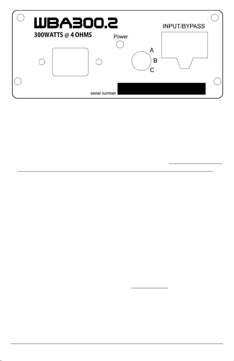
Step #6: Take one amp, and make sure its “Radio Flash Selector Switch” on the side
of the amp is set to position “A”. In the same orientation as it came out of
the box, “stick” the amp to the left half of the plate so the power harness is
closest to the back of the radio. The “amplified output pigtail” will sit closest
to your inner fairing. Have this pig tail so the 4 pin black plug is easy to
get to. This first amp goes on the left (brake side) and from here on out
is referred to as the MASTER amplifier. The second amp powers “other”
speakers on your bike and needs to have the “Radio Flash Selector Switch”
set. Please refer to the middle section of page 7 and set the switch for your
install. With the switch set, take the second amp and “stick it” on your right
(clutch) side oriented the same way as the first amp. From here on out, the
second amp you stick in place is referred to as the SLAVE amplifier.
Step #7: Locate the “splitter” power harness included in the kit. Plug one of the
“splits” into the power connector on each amplifier. Let the balance of the
power harness hang for now.
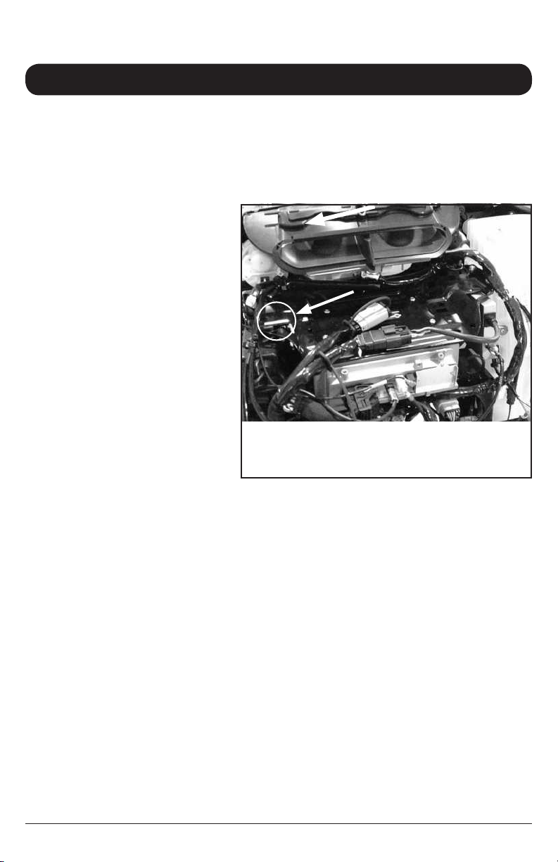
Step #8: On each front speaker’s cabinet, there is a 2 pin plug that has pink and pink
with black stripe wires. The plugs attach the speaker’s wiring to the bike’s
wiring and need to be separated. Locate the “main input” harness and insert
its 8 pin plug into the “audio input” on the MASTER (left side) amplifier. On
this input harness, take the plug with the green heat shrink on the end and
install it into the mating plug on the brake side of the bike. Take the plug with
the yellow heat shrink on the end and install it into the mating plug on the
clutch side of the bike.
Step #9: Locate a bag with a harness in it that says “Audio Out” and plug it into the
amplified out “pigtail” on the Master (left side) amplifier. Take the 2 pin plug
with the blue heat shrink on one end and install it into the plug going into the
brake side speaker cabinet. Take the 2 pin plug with the brown heat shrink
and install it into the plug going into the clutch side speaker cabinet.
Step #10: Locate the bag labeled “input link.” The input link has 2 blue plugs on it,
one of which mates to the empty blue plug on the master (left side) amps
main input harness. Plug these together. The 8 pin plug on the input link
plugs into the “audio in” on the slave (right) amp. This is how we get music
from the master amplifier into the slave amplifier. There will be 1 blue plug
that stays empty which is there for possible future system expansion.
4

5
Step #11: The last connection inside the fairing is to connect the second set of
speakers in the system to the slave (right side) amplifier.
If using Hogtunes lids, the harness included with the lids will work its way
up the bike, and plug right into the amplified out “pigtail” on the slave
(right side) amplifier. If you are installing this on an Ultra Classic model
and have the Wild Boar Audio “WBAURH” Ultra Rear Harness, please
go to the manual that came in that box.
In all other cases (such as lower glove box speakers) you will use the
“ACC” harness that came in this kit that has a 4 pin black plug on
one end, and no plug on the other. This will plug into the amplified out
“pigtail” on the Slave (right side) amplifier and you will “hardwire” your
second set of speakers to this harness. The wires on the supplied ACC
harness are clearly labeled which will make wiring easy, but to avoid
unnecessary warranty calls, please take EXTRA CARE of joining the wires
together.
Step #12: The power/ground harness will pass through the inner fairing where the
main wire harness passes through on the brake side of the bike. If your
comfortable removing and re-installing the fuel tank, the wires can go in
the factory wire “chase”. Alternatively, you can loosen the tank’s “chrome
console” and run wires up and over the gas tank, but under the tank’s
chrome console. There is a provision on the front of the tank console for
wires to pass. NOTE: During some routine bike services, the fuel tank
will be removed. Having the wires going up and over the tank could be
an inconvenience for the technician.
This amplifier comes set up to power front speakers and
speakers either in lids, or fairing lower glove boxes only. If you
are installing this amplifier on an Ultra Classic, you will need a
Wild Boar Audio “WBAURH” Ultra Rear Harness if you want to
power speakers in factory rear speaker “pods”, and have the
radio’s fader function properly.
Stock Harness and Amplifier’s
Harnesses Passing From Fairing To
Just In Front Of Tank (Arrow A).
Cable Tying the Harnesses To The
Main Bike Harness Just In Front Of
The Tank (Arrow B) Allows The Amp
Harnesses To Go Up Towards
The Tank’s Chrome Console Easier
And Makes For a Cleaner Install.

6
Step #13: Attach the splitter harness’ brown wire to the negative (-) battery
terminal and the amp’s red wire to the positive (+) battery terminal.
The factory battery wires are also re-installed at this point. When
attaching the power and ground wires, it is always a good practice to
do the negative first. When the positive connector touches the battery,
some sparking is normal. This is a function of the capacitors in the
amplifier charging up.
Turn the stereo on and, at low volume, test to make sure the speakers
are working. With everything working, re-install the seat making sure
the amplifier’s “+” and “-” connectors are positioned in such a way that
they will not bend or break when the rider’s weight is on the seat.
system Adjustment
Please Note: Having your radio
re-flashed to “4 Speakers No Amplifier”
in all cases is the preferred condition.
As explained at the beginning of this manual, in order for the system to work
properly you will need to have the correct “flash” in your radio. Visit an HD
dealer, or link:
http://technoresearch.com/index.php/tuning-centers.
Any dealer on that web page should be able to help. You either want to have the
correct flash installed, or verify that the correct flash is installed if you are not sure.
There is a 3 position switch “Radio Flash Selector” on the side of the amp marked
A, B, and C. Understanding the correct position for your application is VITAL in the
proper performance of this system.
If you are installing this amplifier on a Ultra Classic model, the factory flash that
came with your bike is the preferred “4 speaker no amp” flash. If your bike has
had no previous audio installed, you will not need a re-flash. If you have questions,
please call our tech support team before proceeding!

• The “Radio Flash Selector” switch positions have been carefully tailored to “work
around” the radio flashes, assuming you have the 4 speaker no amp flash, and
assuming the speakers you are using can handle the power of this amp. For
clarity, all Wild Boar Audio speakers were tested thoroughly with this amp.
• If you have your radio ashed to “4 speaker no amp” set the master and slave
amps to “A”.
• If you have installed the system on a Street Glide or Road Glide but cannot get
the radio reflashed, set the Master and Slave amps to “B”. In ALL cases, having
the radio flashed to “4 speakers no amp” and amps set to “A” is preferred!
If you are not using Wild Boar Audio speakers, and your speakers sound like
they “cant take the power”, putting both amps to the B position should make
things work better.
• In extreme cases only, depending on how the music you have on your USB
source was originally recorded, you may have distortion at around 60-70% of the
volume on your radio. If this is a common issue for you, and you want to have
“full swing” of the radios volume controls, setting the amps to C will fix the issue.
Final Installation Notes:
1) The Wild Boar Audio 600.4 amp has been designed to give great sound with
the radio bass and treble controls in the middle position. Adjusting the bass
and treble up or down no more than 3 bars from center will give excellent
and reliable performance for most kinds of music. If you choose to exceed this
suggestion and play at high volume levels, you may damage your system!
2) The Wild Boar Audio 600.4 amplifier is a HIGH POWER amplifier specifically
designed to work on the small charging system of a motorcycle. DO NOT
start your motorcycle with the radio past half on the
volume dial! When the start button is hit, all available current goes to
your bikes starter which “starves” the amplifier and may cause damage to
your system!
7

8
Before re-installing outer fairing, turn front wheel
to each extreme side making sure any wiring is
not impeding the steering of the motorcycle.
Failure to do so can result in serious
injury or death!
Re-install the fairing and the system is now ready to enjoy!
Warranty information is at the back of this manual
Please go to page 17 and record your
amplifier’s serial numbers

9
roAd glide / roAd glide
ultrA instAllAtion
section 2

10
As the amplifiers come in the box, they are “stuck” to a mounting plate for use in
FLH (Batwing) model bikes. “Peel” the amps off the plate and put that plate aside
as it’s not required for FLTR (Road Glide) installations.
In order for the system to work properly you will need to have the correct “flash”
in your radio. Visit an HD dealer, or link:
http://technoresearch.com/index.php/tuning-centers.
Any dealer on that web page should be able to help. You either want to have the
correct flash installed, or verify that the correct flash is installed if you are not sure.
In all cases, the preferred radio flash is called “4 speaker no amp”. There is a
3 position switch “Radio Flash Selector” on the side of each amp marked A, B,
and C. Understanding the correct position for your application is VITAL in the
proper performance of this system. More detail on these position is later in the
manual right before the amps get physically mounted to your bike.
The image below will be one you can reference throughout the installation. Please
take a minute and familiarize yourself with the items listed below in the image.
roAd glide instAllAtion
section 2
A
B
CD
Figure 1.1
A = Mounting points for Headlight assembly
B = Wire passage from fairing to bike
C = Brake side speaker harness (Pink and Pink with Black Stripe wires)
D = Clutch Side Speaker harness (Pink and Pink with Black Stripe wires)

11
Step #1: Locate the “splitter” power harness included in this kit. You will see one
end that has “ring terminals”, and the other end that “splits” and has 2
power connectors on it. Using the image on the bottom of Page 10 for
reference, run the “ring terminal end” of the power harness through “B”.
Position it so the 2 power connectors on the “split end” are accessible in
the inner fairing and the slack can be adjusted later in the installation.
Just in front of the tank, there is a structure that attaches the fairing to the
frame of the bike. The power harness will pass through this structure and
exit through the rectangular opening where the factory harness also exits
the structure on the BRAKE side of the bike. Note: it can be easier to
pass the wire harness through the rectangular opening if you “open” the
fuse holder and remove the fuse before passing the wire harness. Once
the ring terminal end of the wire harness is through the rectangular
opening and most of the slack is taken up, move to the next step.
Step #2: Preparing the Plate For the Amplifiers:
Locate the main plate that came in the kit
(Fig 1.2). Locate the 2 “hook and loop”
adhesive pieces included in the kit and
separate the halves of each. With the plate at
room temperature or higher, apply one side
of the hook and loop to the front of the plate
as shown by the black rectangle also is Fig
1.2. Apply a second piece on the back of the
plate as well.
Step #3: “Stick” one of the amplifiers to the BACK of
the plate in the same orientation as shown in
Fig 1.3 with the power harness on the left.
Fig 1.2
Fig 1.3

IMPORTANT
In this install we refer to one amp as the “Master” and the other
amp as the “Slave”. The Master always has the main input
harness go into it, and is always the amp that powers the
front fairing speakers. When installed, the amp on the left
BACK SIDE of the plate is the MASTER AMPLIFIER.
Step #5: Using the image on the bottom of Page 10 for reference, locate the
4 bolts on each of the 4 corners around “B” and remove the ones on
top left and top right (only). You will move the plate with the Master
amp to the bike now.
Step #6: Using the image on the bottom of Page 10 for reference, locate “C” and
“D” which are the 2 pin plugs on each front speaker’s cabinet that have
pink and pink with black stripe. These plugs attach the speaker’s wiring
to the bike’s wiring and need to be separated. Locate the “main input”
harness and insert its 8 pin plug into the “audio input” on the MASTER
(back side) amplifier. On this harness, take the plug with the green heat
shrink on the end and install it into the mating plug on the brake side of
the bike. Take the plug with the yellow heat shrink on the end and install
it into the mating plug on the clutch side of the bike.
Step #7: Locate a bag with a harness in it that says “Audio Out” and plug it
into the amplified out “pigtail” on the Master (back) amplifier. Take the
2 pin plug with the blue heat shrink on one end and install it into the
plug going into the brake side speaker cabinet. Take the 2 pin plug
with the brown heat shrink and install it into the plug going into the
clutch side speaker cabinet.
Take one of the 2 power connectors on the splitter harness, and plug it
into the power connector on the Master (back) amplifier.
Step #8: Locate the bag that came in the dual amp kit labeled “input link.” The
input link has 2 blue plugs on it, one of which mates to the empty blue
plug on the Master (back side) amps main input harness. Plug these
together and let the rest of the input link harness hang for now.
IMPORTANT—Before you proceed, make sure you
understand the Radio Flash Selector info on the next
page. The Master (back side) Amp will be difficult
to adjust later if you don’t do this now!
12

13
Step #10: The “Radio Flash Selector” switch positions have been carefully tailored
to “work around” the radio flashes, assuming you have the 4 speaker
no amp flash, and assuming the speakers you are using can handle
the power of this amp. For clarity, all Wild Boar Audio speakers were
tested thoroughly with this amp.
If you have your radio flashed to “4 speaker no amp” set the master
and slave amps to “A”.
If you have installed the system on a Street Glide or Road Glide but
cannot get the radio reflashed, set the Master and Slave amps to “B”.
In ALL cases, having the radio flashed to “4 speakers no amp” and
amps set to “A” is preferred! If you are not using Wild Boar Audio
speakers, and your speakers sound like they “cant take the power”,
putting both amps to the B position should make things work better.
In extreme cases only, if you regularly listen to music on your USB
source that has been recorded at unusually high levels, and its causing
the system to distort prematurely, set the amps to C. This would be a
“last case” after talking to our tech support people. On initial installa-
tion A or B should be used depending on the flash in your radio.
Step #10: Using the image on page 10 for reference, you will see 2 large
factory harnesses between “A” and “B”. Wiggle the amp/plate into
place around these harnesses so that the holes on the “legs” at the
bottom of the plate line up with the holes where the factory bolts
around “B” were.
With the plate in position, reinstall the factory bolts around “B” which
will secure the Master amp on its plate to the bike.
Step #11: Take the second (Slave) amp and plug the second power connector
from the splitter power
into the amp. There is
a 8 pin plug on the
“input link” which will
get plugged into the
“audio input” on the
front (slave) amp.
You can now “stick”
the Slave (front)
amplifier to the
plate in the same
orientation as
shown in Fig 1.4.
Fig 1.4

14
Step #11: The last connection to the Slave (front) amplifier is to the second set of
speakers in your system.
If using Hogtunes lids: the harness that comes with the lids will
work its way up the bike, and plug right into the amplified out “pigtail”
on the Slave (front) amplifier.
If you are installing this on a Road Glide Ultra and have the Wild Boar
Audio “WBAURH” Ultra Rear Harness, please go to the manual that
came in that box.
In all other cases (such as lower glove box speakers) you will use the
“ACC” harness that came in this kit that has a 4 pin black plug on
one end, and no plug on the other. This will plug into the amplified out
“pigtail” on the Slave (right side) amplifier and you will “hardwire”
your second set of speakers to this harness. The wires on the supplied
ACC harness are clearly labeled which will make wiring easy, but to
avoid unnecessary warranty calls, please take EXTRA CARE of joining
the wires together.
Step #12: If your comfortable removing and re-installing the fuel tank, the wires
can go in the factory wire “chase”. Alternatively, you can loosen the
tank’s “chrome console” and run wires up and over the gas tank, but
under the tank’s chrome console. There is a provision on the front of
the tank console for wires to pass. NOTE: During some routine bike
services, the fuel tank will be removed. Having the wires going up and
over the tank could be an inconvenience for the technician.
Step #13: Attach the amp’s brown wire to the negative (-) battery terminal and
the amp’s red wire to the positive (+) battery terminal. The factory
battery wires are also re-installed at this point. When attaching the
power and ground wires, it is always a good practice to do the
negative first. When the positive connector touches the battery, some
sparking is normal. This is a function of the capacitors in the amplifiers
charging up.
This amplifier comes set up to power front speakers and
speakers either in lids, or fairing lower glove boxes only. If you
are installing this amplifier on a Road Glide Ultra, you will need
a Wild Boar Audio “WBAURH” Ultra Rear Harness if you want
to power speakers in factory rear speaker “pods”, and have the
radio’s fader function properly.

15
Step #14: Turn the stereo on and, at low volume, test to make sure the speakers
are working. With everything working, re-install the seat making sure
the amplifier’s “+” and “-” connectors are positioned in such a way that
they will not bend or break when the rider’s weight is on the seat.
Step #15: If you have not already done so, PLEASE get the radio on the bike
flashed to “4 speaker no amp”. Visit an HD dealer, or link:
http://technoresearch.com/index.php/tuning-centers.
Any dealer on that web page should be able to help. You either want
to have the correct flash installed, or verify that the correct flash is
installed if you are not sure. If you operate your system at high volumes
without the correct radio flash, the system will “ break up” much earlier
than it should, and may cause damage to your speakers!
Final Installation Notes:
1) The Wild Boar Audio 600.4 amp has been designed to give great sound with
the radio bass and treble controls in the middle position. Adjusting the bass
and treble up or down no more than 3 bars from center will give excellent
and reliable performance for most kinds of music. If you choose to exceed this
suggestion and play at high volume levels, you may damage your system!
2) The Wild Boar Audio 600.4 amplifier is a HIGH POWER amplifier specifically
designed to work on the small charging system of a motorcycle. DO NOT
start your motorcycle with the radio past half on the volume
dial! When the start button is hit, all available current goes to your bikes
starter which “starves” the amplifier and may cause damage to your system!
Before re-installing outer fairing, turn front wheel
to each extreme side making sure any wiring is
not impeding the steering of the motorcycle.
Failure to do so can result in serious
injury or death!
Re-install the fairing and the system is now ready to enjoy!
Warranty information is at the back of this manual.

16
WBA 600.4 Quick Reference Wiring Diagram
A) Factory Connectors Between Radio and Speaker Cabinets (pink/pink with black stripe)
B) Master Amp Brake Side Input (Green Heatshrink)
C) Master Amp Clutch Side Input (Yellow Heatshrink)
D) Master Amp Brake Side Output (Blue Heatshrink)
E) Master Amp Clutch Side Output (Brown Heatshrink)
F) Master Amp Amplified Output “Pigtail”
G) Master Amp Bypass Out
H) Input Link From Master Amp to Slave Amp
I) Slave Amp Bypass Out For Possible Future System Expansion
J) Slave Amp Amplified Output Pigtail for Lids Or “ACC” Harness
K) Amplifier Main Power/Ground
This Page Is For Quick Reference Only.
To Avoid Damage To Your System, Please Read Entire Manual!

17
Wild Boar Audio branded amplifiers are warranted for a period of 3 years to
the original purchaser. Proof of purchase is required for all warranty claims.
Products found to be defective during the warranty period will be repaired or
replaced (with a product deemed to be equivalent) at Wild Boar Audio’s sole
discretion. Wild Boar Audio’s complete warranty policy is available on the website
at www.wildboaraudio.com
Please note: in the event of a warranty claim, if one of the 2 amplifiers that make
up WBA 600.4 fails, we will replace the defective amplifier ONLY!
What Is Not Covered:
1) Any expense related to the removal or re-installation of products.
2) Repairs to these products performed by anyone other than Hogtunes, Inc.
3) Subsequent damage to any other components.
4) Any product purchased from a non-authorized Wild Boar Audio dealer.
5) Damage to products from an accident or collision.
6) Damage from incorrect installation, improper use, abuse or modifications.
7) Reduction of FM reception.
8) Damage caused by incorrect factory radio “re-flash” and amp combination
9) Damage to inbound warranty product due to improper packing.
IMPORTANT: In the event of a warranty claim, please fill
out the form in the Warranty section of our website
www.wildboaraudio.com. Valid claims will have a Return
Authorization Number (RA#) generated which MUST appear
on the outside of the box when it arrives to our offices.
Goods Arriving Without An RA# Will Be Refused!
warranty information
Please record your amplifier’s serial #’s here:
“Master aMp”
“slave aMp”
Wild Boar Audio is owned by Powersports Audio Inc.

Wild Boar Audio products will play much louder than the
Original Equipment, which can be a distraction to
the rider and/or passenger. Please use caution
when adjusting or playing your stereo
at high volume, especially in traffic.
You are a valued customer so please:
Ride Alert
Arrive Alive!
www.wildboaraudio.com
www.hogtunes.com
Version 1.4
Table of contents
Other Hogtunes Amplifier manuals

Hogtunes
Hogtunes REV 200-AA User manual

Hogtunes
Hogtunes NCA70.2 User manual

Hogtunes
Hogtunes Quadcast QC475-RM User manual

Hogtunes
Hogtunes Wild Boar Audio WBA 400.2R User manual

Hogtunes
Hogtunes NCA 40.4 User manual

Hogtunes
Hogtunes REV 200SG KIT-RM User manual

Hogtunes
Hogtunes Wild Boar Audio WBA 800.4SG KIT User manual

Hogtunes
Hogtunes NCA 450-RM User manual

Hogtunes
Hogtunes REV 200-RM User manual

Hogtunes
Hogtunes WILD BOAR AUDIO WBARG KIT 2R User manual