7
This section is VITAL to the correct operation
of the system, please make sure you read
and understand it, or contact us!
The correct flash required for this system is the exact same one that comes in FLH
Ultra Classics (non CVO Models). The factory refers to this flash as “upper fairing/
rear pods, zero amps”. We understand that the flash we say to use indicates “zero
amps” and that there is an amp in this system. The flash we indicate to use gives
the correct sound and audio levels from the radio for the system to work correctly.
You can also visit a “Techno Research” dealer as they can flash the radio as well.
Techno Research dealers have a “Wild Boar Audio” Flash built in to their systems
which is identical to the required factory flash. You can look for a Techno Research
dealer by using the web link https://technoresearch.info/tuning-centers-map/
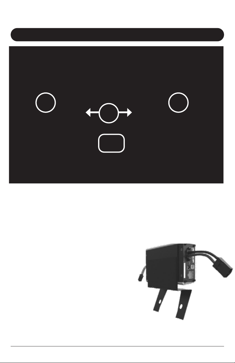
There is a 3 position “Radio Flash Selector” on the side of the amp marked A,B,
and C. In all cases, having the correct radio flash installed, and having the “Radio
Flash Selector” set to “A” is the preferred setting!
There is a 3 position “Radio Flash Selector” on the side of the amp marked
A,B, and C. In all cases, having the correct radio flash installed, and
having the “Radio Flash Selector” set to “A” is the preferred setting!
POSITION “A”
For “Non CVO” 15+ Road Glide or Road Glide Special, with the correct “front
and rear speakers without amp” or “Wild Boar Audio” flash installed, the switch
needs to be in the “A” position.
POSITION “B”
If you have installed this system but cannot get to a dealer for the correct flash,
put the switch to position B. In all cases, having the correct radio flash
installed, and having the “Radio Flash Selector” set to “A” is the
preferred setting!
POSITION “C”
Position C is there for any changes the factory may introduce in the future, and
SHOULD NOT be used for this installation.
RADIO FLASH INFORMATION
section 3