Hogtunes Wild Boar Audio Wbass Kit User manual

WBASG Kit
INSTALLATION MANUAL
IMPORTANT!
A Radio “Re-Flash” Is Strongly Encouraged
Before Proceeding. Please Read Manual For More Information

Wild Boar Audio Contact Information
Tel: 705-719-6361
Thank you for your purchase of Wild Boar Audio’s Amp with Front
Speaker Kit specifically made for “Rushmore” platform Street Glide®
and Ultra Classic® models. We want your new kit to work as well as
it was designed to, so if you have any questions or concerns, please
705-719-6361 (EST). If you still need help, please consider a
professional installation by your dealer.
Important:
This is a powerful system, and needs to be adjusted correctly for the
recommended dealer radio re-flash, or damage may occur. We
STRONGLY suggest reading this entire manual before proceeding!
This manual is written in 3 major sections:
Step 1: Speaker Installation
Step 2: Amplifier Installation
Step 3: Final System Adjustments/Radio Re-flash info
Please read the notes on the next page
before proceeding with the installation

1
This system requires a radio re-flash by a dealer to work properly. This is
explained in Section 3 of the manual. Please DO NOT ignore this important step,
or the system will not work as well as it has been designed to.
With the correct radio flash, the system can play at high levels with virtually no
audible distortion. The amplifier has built in protection. You will know you are
at the limits of the system if one channel of the amp turns off and back on. This
typically all happens in less than a second. Channels turning on and off quickly is
letting you know to adjust the volume down slightly. The tweeters on the speakers
are also protected by a poly thermal coefficient (PTC) switch. This heat sensitive
switch will temporarily turn the tweeter off until the switch cools off, and will then
turn the tweeter back on. This will only happen at high volumes.
Many users take advantage of the convenience of ‘streaming” music to the radio
using Bluetooth® Wireless Technology. It should be noted that plugging in the
music device using the radios USB cord sounds better and plays louder than using
Bluetooth. Make sure that any equalizers on the music playback device are OFF.
There are many different styles of amplifiers. Wild Boar Audio is a Class D design
as this is the best choice for high power on vehicles with smaller charging systems.
The main advantages of Class D are:
• Very efcient design (Big power output while not being too hard on bike’s
charging system)
• Much lower amplier heat compared to other designs
• Amplier can be much smaller compared to other designs
The downside to Class D design is that it can interfere with FM reception.
Although every effort has been made to reduce any FM interference, it is possible
to have some stations not come in clearly. For this reason, if FM reception is a very
important part of your listening, we strongly advise against the use of in fairing
antennas. After considerable testing, we have concluded that nothing works as
well as the factory antenna which is why Wild Boar Audio and Hogtunes do not
offer in fairing antennas.
BEFORE GETTING STARTED

2
Step #1: Remove the bikes seat, and undo the main (+ and -) connectors from the
battery. Remove the outer fairing/headlamp assembly and set aside.
Refer to a service manual if you need help with this. NOTE: Placing a
towel on the front fender can help prevent scratches or “dings” from
dropped tools or fasteners, etc.
Step #2: Speaker Cabinet Removal:
On the brake side speaker cabinet,
carefully remove the cable going into the
power port/cigarette lighter assembly.
If the bike has the CB module (mounted
“sideways” on the clutch side cabinet)
undo the antenna cable and main har-
ness. The CB Module will stay attached
to the clutch side cabinet when removed.
Undo the speaker wire plugs going into
each cabinet (pink & pink with black
stripe wires).
Removing the Factory Cabinets:
It is STRONGLY recommended to com-
plete the speaker swap on one side be-
fore moving to the other side! Figure 1.1
and 1.2 have arrows that point to all 8
factory fasteners (per side) that will be re-
moved to allow each cabinet to come out
of the bike. Although the brake side is
shown below, all 8 fastener locations are
common for both brake and clutch side
cabinets. In Fig 1.1 you will see where
the speaker wire exits the cabinets. The 3
cabinet fasteners below the speaker wire
are 7/16” heads that will also accept
a 3/16” allen head. A “ratcheting box
end” or “ball end” allen wrench will
make removing these 3 fasteners much
easier!
Figure 1.1
Side view
of brake
side
cabinet
Figure 1.2
Back view of
brake side
cabinet
SIDE VIEW
BACK VIEWBACK VIEW
SPEAKER INSTALLATION
section 1

3
Step #3: Installing the Speaker:
With the cabinet removed from the bike, undo the 4 screws that hold
the factory speaker to the cabinet and put these screws aside. Pull the
factory speaker away from the cabinet and carefully take off each
speaker wire by un-doing one at a time. Take a Wild Boar Audio
speaker and attach the speaker wires noting the factory speaker wire
connectors will lock into place on the speaker. Sit the Wild Boar Audio
speaker into the cabinet noting the speaker MUST be oriented so that
the wires are in the bottom (6 o’clock) position so the speaker frame
will not touch the small locater peg that sticks out from the face of the
cabinet. If the speaker is not placed correctly, the speaker may not
“seal” correctly to the cabinet and the bass response will suffer! Using
the supplied screws (which are longer than the factory screws), attach
the new speaker to the cabinet.
Repeat Step #3 for the second cabinet
Make sure to plug the power cable back into the power port/cigarette
lighter assembly on the brake side. If the bike has the CB module, make
sure to re-install the antenna cable and main harness. Let the factory
speaker wires that come out of the cabinets “hang” for now.

Step #1: Over top of the radio,
pull up to release each
wire harness from the
black plate via the
factory “Christmas
Tree” fasteners. If the
bike has factory GPS,
the small square an-
tenna will need to be
relocated just behind
the voltmeter as shown
in Fig 1.1. Remove
the four factory T-20
“Torx” screws that go
through the top of the
black plate and into
the top of the radio. The amplifier comes pre-mounted to a silver mount-
ing plate. Locate and remove the four screws (2 per side) that attach the
amp to the silver plate. Put these screws (just removed) and the amplifier
aside for now.
Step #2: Place the supplied silver
plate on top of the radio
so it is oriented as shown
in Fig 1.2. Locate one of
the supplied “star” washers
on each factory screw and
re-install the screw/washer
through the silver plate,
through the factory black
plate and into the top of
the radio. Locate the main
power harness and plug it
into the matching “pig-tail”
on the side of the amp.
Locate the harness with a
4 pin black plug and insert
into the “audio out” on the
side of the amp. Locate
the harness with the 8 pin
AMPLIFIER INSTALLATION
section 2
Figure 1.1 - The white circle shows the new
location for GPS Antenna if your bike came
factory equipped with this feature.
Figure 1.2 - Amplifier and mounting plate
correctly oriented. The plate with four small
holes is for mounting a popular Harley
accessory. The white circles show tabs which
are there for the “Christmas Tree” fasteners
to re-secure the harnesses lifted earlier.
4

white plug and insert it into the “audio in” on the side of the amp. Sit the
amp on top of the silver plate so when standing in front of the bike, the
power harness is on your left (aka the BRAKE SIDE of the bike). Re-install
the amp to the plate using the four screws removed earlier.
Also in Fig 1.2 is a white square which shows a smaller black 2 pin
factory plug. The orange wire from the amp has a plug that goes directly
into this factory harness. On the factory plug described, there may be
a factory plug with no wires already installed into it which will have to
be removed. The factory wire colors going into the plug are purple/
blue stripe and black and can be see under the factory sheathing. The
orange wire is the amplifier “turn on” lead and tells the amp to turn on/
off with the bike’s ignition. The amplifier will not turn on if this wire is not
hooked up to this (or any) switched B+ source!
Step #3: On the 4 pin black plug now installed into the amplified output on the
amp, locate the end with the green heat shrink and plug it directly into
the brake side speaker cabinet noting it will only go in one way. On the
8 pin plug now installed into the input socket on the amp, locate the end
with the green heat shrink and plug it directly into the factory connector
that originally plugged directly into the brake side speaker cabinet (has
pink/pink with black stripe wires).
Step #4: On the 4 pin black plug now installed into the amplified output on the
amp, locate the end with the yellow heat shrink and plug it directly into
the clutch side speaker cabinet noting it will only go in one way. On the
8 pin plug now installed into the input socket on the amp, locate the end
with the yellow heat shrink and plug it directly into the factory connector
that originally plugged directly into the clutch side speaker cabinet (has
pink/pink with black stripe wires).
The power/ground harness will pass together the inner fairing where the
main wire harness passes through on the brake side of the bike. Loosen
the tank’s “chrome console” and run wires up and over the gas tank,
but under the tank’s chrome console. There is a provision on the front of
the tank console for wires to pass. NOTE: Although not necessary, the
power and rear harnesses can go under the gas tank if you choose to
remove and re-install the tank.
5

Figure 1.3 - Stock Harness
and Amplifier’s Harnesses
Passing From Fairing To Just In
Front Of Tank (Arrow A). Cable
Tying the 2 Amp Harnesses To
The Main Bike Harness Just
In Front Of The Tank (Arrow
B) Allows The Amp Harnesses
To Go Up Towards The Tank’s
Chrome Console Easier And
Makes For a Cleaner Install.
A
BBA
6
Step #5: Attach the amp’s black wire to the negative (-) battery terminal and the
amp’s red wire to the positive (+) battery terminal. The factory battery
wires are also re-installed at this point. When attaching the power and
ground wires, it is always a good practice to do the negative first. When
the positive connector touches the battery, some sparking is
normal. This is a function of the capacitors in the amplifier charging up.
Turn the stereo on and, at low volume, test to make sure the speakers
are working. With everything working, re-install the seat making sure the
amplifier’s “+” and “-” connectors are positioned in such a way so they
will not bend or break when the rider’s weight is on the seat.
Before you start to “clean up” the wiring,
please MAKE SURE to route the amplifiers wires
(blue/silver) that go to the brake side of the bike on
top of the amp, but as close to the inner fairing as
you can. This is the best time to take a few minutes
to “clean up” the wiring and secure using supplied
zip-ties. Under NO CIRCUMSTANCES should any of
the blue/silver wires be zip tied to any factory
antenna cables anywhere on the bike.
installation tip

7
This section is VITAL to the correct operation
of the system, please make sure you read
and understand it, or contact us!
Step #1: In order for the system to work properly you will need to have the correct
“flash” in your radio. You can go to an HD dealer, or if you visit the
link http://technoresearch.com/index.php/tuning-centers, any dealer
on that web page should be able to help. You either want to have the
correct flash in-stalled, or verify that the correct flash is installed if you
are not sure.
There is a 3 position switch “Radio Flash Selector” on the side of the
amp marked A, B, and C. Understanding the correct position for your
application is VITAL in the proper performance of this system.
Position “A”
If you have a “Non CVO” 14+ Street Glide or Street Glide Special,
please have the dealer Re-flash the radio to “4 Speakers No Amplifier”
If installing this kit in a “Non CVO” 14+ Ultra, the factory radio comes
re-flashed from the factory as “4 Speakers No Amplifier.” If the system
has not had any audio changes made from the factory, you should not
need the re-flash although you may want to visit a dealer to be sure that
you have the correct re-flash!
Once you are sure you have the radio flash “4 Speakers No
Amplifier” in your radio, set the 3 position switch to “A” and proceed
to Final Install Notes.
SYSTEM ADJUSTMENT
section 3
Radio
Flash
Selector
A
B
C
Important!
Refer To
Manual

Please Note: Having your radio re-flashed to
“4 Speakers No Amplifier” in all cases is the preferred condition.
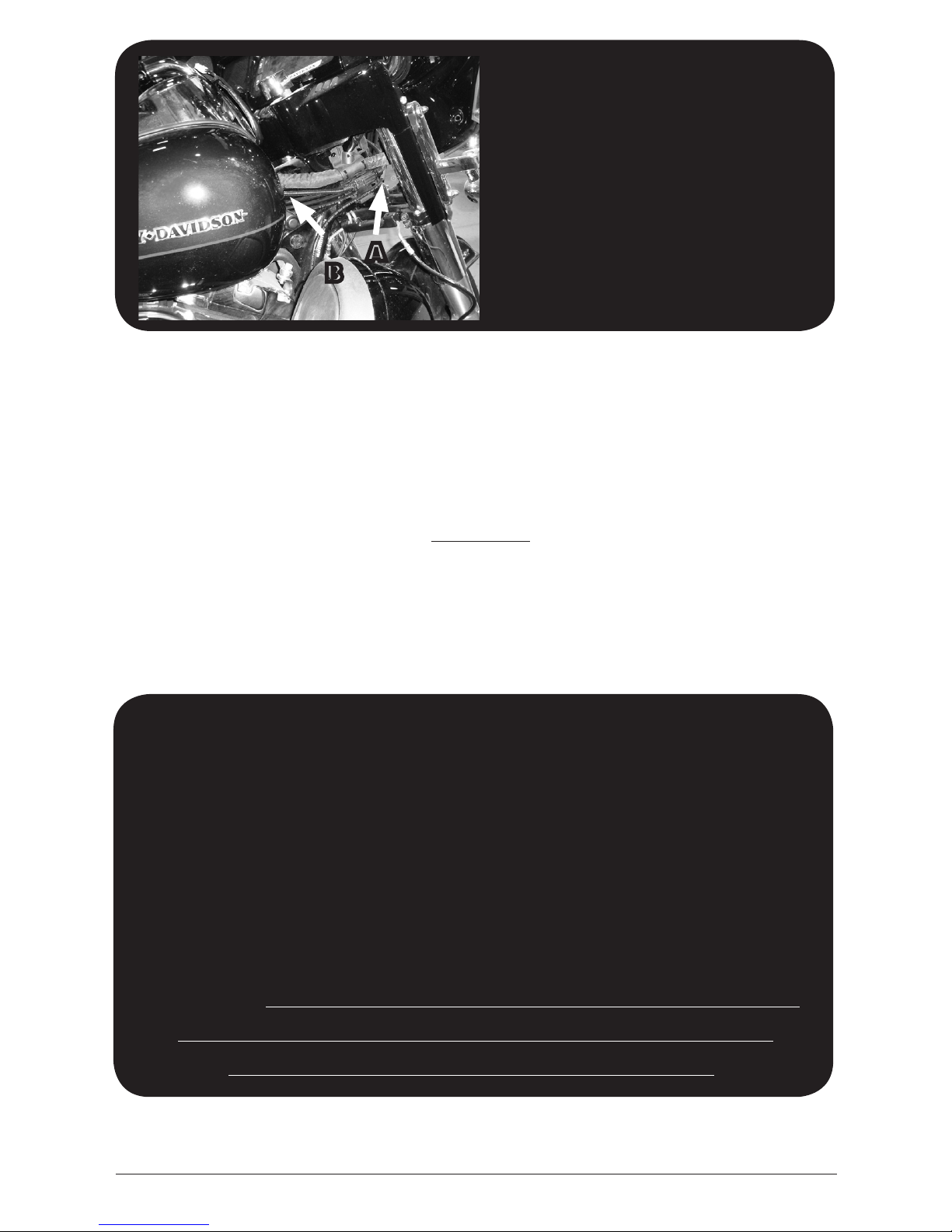
With this flash, and the amp set to “Position A” You will
get the best volume and your radio’s AVC
(Automatic Volume Control) will work.
Position “B”
If you have a Non CVO Street Glide and cannot get to a dealer for the
re-flash, set the amp to Position B. This is a “usable” setting, but you
will not be able to have your bass in the middle position without some
“break up” at high volume. At high volume, you may also experience
either side of the amplier turning off momentarily. The bikes AVC
(Automatic Volume Control) will work. The correct ash for “Position A”
is recommended for the best performance.
Position “C”
If you have a Non CVO Street Glide and are replacing a previously
installed factory amplier, or have a CVO model and are replacing the
fairing amplifier, the radio should have the “2 speaker 1 amp” flash.
Setting the 3 position switch on the side of the amp to “Position C” will
work in this case, however, the radios AVC (Automatic Volume Control)
will NOT work. The correct flash for “Position A” is recommended for the
best performance.
Final Installation Notes:
1) Many users will store music on a hand held type player and use that as the
music source for the bikes audio. PLEASE NOTE: If you “borrow” music files
from certain sites, they typically sound poor. Using a good quality file will only
make the system sound better!
2) Many users will take advantage of the convenience of “streaming” their
music to the radio using Bluetooth®. It should be noted that it was found that
plugging in the music device using the radios USB cord sounds better and
plays louder than using Bluetooth®.
3) Assuming you have the “4 Speaker No Amp” flash and the 3 position switch
on the side of the amp is set to “A”, we suggest having the bass on the radio
set to 1 or 2 bars above the center position, and the treble set to one or 2
bars below the center position. If you have bass heavy music, and are hearing
some “break up” there is nothing wrong with lowering the bass control on
the radio till everything sounds “right”. You can set the bikes AVC (Automatic
Volume Control) however you like it.
8

9
Before re-installing outer fairing, turn front wheel
to each extreme side making sure any wiring is
not impeding the steering of the motorcycle.
Failure to do so can result in serious
injury or death!
Re-install the fairing and the system is now ready to enjoy!
Wild Boar Audio branded speakers are warranted for a period of 5 years to
the original purchaser. Wild Boar Audio branded amplifiers are warranted for a
period of 3 years to the original purchaser. Proof of purchase is required for all
warranty claims. Please contact Hogtunes head office for all warranty claims.
Products found to be defective during the warranty period will be repaired or
replaced (with a product deemed to be equivalent) at Hogtunes sole discretion.
Hogtunes/Wild Boar Audio’s complete warranty policy is available on our website
at www.hogtunes.com
What Is Not Covered:
1) Any expense related to the removal or re-installation of products.
2) Repairs to these products performed by anyone other than Hogtunes, Inc.
3) Subsequent damage to any other components.
4) Any product purchased from a non-authorized Wild Boar Audio dealer.
5) Damage to products from an accident or collision.
6) Damage from incorrect installation, improper use, abuse or modifications.
7) Damage caused by incorrect factory radio “re-flash” and amp combination
8) Damage to inbound warranty product due to improper packing.
IMPORTANT: In the event of a warranty claim, please fill out the
form in the Warranty section of our website www.hogtunes.com.
Valid claims will have a Return Authorization
Number (RA#) generated which MUST appear on the outside
of the box when it arrives to our offices.
Goods Arriving Without An RA# Will Be Refused!
warranty information

Wild Boar Audio products will play much louder than the
Original Equipment, which can be a distraction to
the rider and/or passenger. Please use caution
when adjusting or playing your stereo
at high volume, especially in traffic.
You are a valued customer so please:
Ride Alert
Arrive Alive!
www.wildboaraudio.com
www.hogtunes.com
Version 1.1
Table of contents
Other Hogtunes Amplifier manuals

Hogtunes
Hogtunes WILD BOAR AUDIO WBA 600.4 User manual

Hogtunes
Hogtunes NCA 450-RM User manual

Hogtunes
Hogtunes Quadcast QC475-RM User manual

Hogtunes
Hogtunes REV 200-AA User manual

Hogtunes
Hogtunes REV 200SG KIT-RM User manual

Hogtunes
Hogtunes WILD BOAR AUDIO WBARG KIT 2R User manual

Hogtunes
Hogtunes NCA70.2 User manual

Hogtunes
Hogtunes Wild Boar Audio WBA 800.4SG KIT User manual

Hogtunes
Hogtunes USA 24.2 User manual

Hogtunes
Hogtunes REV 200-RM User manual