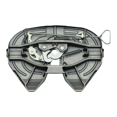
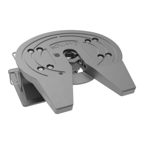
Holland XA-3501-03505 Series Manual

FIFTH
WHEELS
XL-FW313-01 Rev C 1
GO THE DISTANCE.
HITCH
OPERATING AND
MAINTENANCE PROCEDURES
XA-3501-03505 Series
Yard Spotter Fifth Wheel Top Plates
FIGURE 1
FIFTH WHEEL TILTED DOWN
FIFTH WHEEL
MUST LIFT
TRAILER
➠
➠
4˝- 6˝
USE LOW GEAR
FIGURE 2
SAFETY INSTRUCTIONS
1. Failure to read, understand, and follow the
important information contained herein may
result in a hazardous condition, or cause a
hazardous condition to develop.
2. Relative to tractor-trailer operations, there are
other checks, inspections, and procedures not
listed here, which are necessary, prudent,and/or
required by law. The following is in addition to
these and pertains to the fifth wheel only.
3. Perform these procedures in an area clear of
obstacles and other personnel.
CHECK EQUIPMENT PRIOR TO USE
1. Make sure the fifth wheel is properly lubricated.
2. Make sure the secondary lock is disengaged.
(See FIGURE 1).
3. Make sure the fifth wheel locks are open.
4. Make sure the fifth wheel ramps are tilted down
as shown in FIGURE 2.
COUPLING
1. Back up close to the trailer, centering the king-
pin in the throat of the fifth wheel. STOP. Set
tractor brakes.
2. Block the trailer wheels, connect brake lines and
set trailer brakes.
3. Check to see that the trailer is at the proper
height for coupling. (The front of the bolster
plate should contact the fifth wheel approxi-
mately 4˝ to 6˝ behind the fifth wheel’s pivot
point. If not, raise or lower the fifth wheel and,
if necessary, the trailer landing gear, to obtain
this position.)
continued
Manual
secondary
lock handle
Secondary lock
disengaged
Fifth wheel
locks are
open

UNCOUPLING
1. Position yard spotter tractor and trailer on firm,
level ground — clear of obstructions and people.
2. Set trailer brakes, lower fifth wheel until
the trailer landing gear touch the ground.
Set tractor brakes.
3. Block trailer wheels. Disconnect trailer
air supply and electrical connection.
4. If the manual secondary lock was engaged,
remove the hairpin clip on the secondary lock
handle, pull the secondary lock handle out-
ward to disengage the secondary lock. While
holding the handle out, re-insert the hairpin
clip into the hole in the handle on the outside
of the handle guide. (See FIGURE 5.)
5. Actuate the fifth wheel control valve and hold
it in to open the locks.
6. While holding the lock control valve in, slowly
pull out from the trailer.
7. After driving completely free of the kingpin,
release the lock control valve.
All elevating fifth wheels
— when towing trailers
in the elevated position —
are less stable than
conventional tractor-trailers
and are sensitive to speed
and maneuvers.
This unit is not recommended for operation on
public streets and highways. When such trailer
moves are necessary, the manual secondary
lock on the fifth wheel must be engaged (see
coupling procedure #5 at left) and the fifth
wheel must be in the down position. Limit
speed to 45mph maximum.
WARNING
4. Back under the trailer and engage the fifth
wheel locks with the trailer kingpin. Pull for-
ward to test the completeness of the coupling
as an INITIAL check. Set tractor brakes. Next,
visually inspect the fifth wheel, as shown in
FIGURE 3, to verify that it is properly locked.
5. If operation on public streets or highways is
required, the manual secondary lock must be
engaged. To engage the secondary lock, re-
move the hairpin clip on the secondary lock
handle allowing the secondary lock to pivot
and engage behind the locking yoke as shown
in FIGURE 4.
6. Remove blocks. Retract the landing gear, if nec-
essary. Release trailer and tractor brakes. Raise
trailer to desired height and move trailer.
WARNING
Failure to verify a proper
couple can result in tractor
and trailer separation causing
death or serious injury to
you or others.
LOCKS COMPLETELY CLOSED AROUND KINGPIN
View looking into the throat of the fith wheel
Bolster plate is flush
with the fifth wheel
FIGURE 3
SECONDARY LOCK DISENGAGED
MANUAL
SECONDARY
LOCK
HANDLE
SECONDARY LOCK
DISENGAGED
MANUAL
SECONDARY
LOCK HANDLE
GUIDE
2
SECONDARY LOCK
ENGAGED
MANUAL
SECONDARY
LOCK HANDLE
SECONDARY
LOCK ENGAGED
FIGURE 4
FIGURE 5
XL-FW313-01 Rev C

XA-3501-03505 AND XA-3501-UB PARTS BREAKDOWN
3
ITEM NO. ITEM NO.
NO. PART NO. REQ’D. PART NAME NO. PART NO. REQ’D. PART NAME
12
18
16
16
11
17
13
14 13
12 12
20
19
15
6
7
23
22
24
9
10 21
98
25
25
5
2
1
43
4
3
30
27
28
26
30 29
26
28
27
USED ONLY ON
XA-3501-03505
USED ONLY ON
XA-3501-03505
30
30 29
NOTE:
When replacing bracket bearings (Item 29), remove
only one bearing stop block (Item 30) from each side.
Replace bearings and install new stop blocks.
1* XA-1704-X 1 Lock Set
2 XB-GT-13-1 1 Extension Spring
3 XA-1313 2 Lock Pin
4 XB-5 2 Cotter Pin
5 XA-07295-THK 1 Yoke
6 XA-1706-1 1 Yoke Shaft
7 XB-1505 1 Spring
8 XA-1707-5 1 Release Handle
9 XB-PW-1732-1-116 2 Washer
10 XB-1028-1 1 Compression Spring
11 XA-1705-7 1 Cam Plate Sub Assembly
12 XB-2083 3 Hex Hd. Cap Screw 1⁄2˝20x13⁄4˝
13 XB-T-49 2 Washer
1⁄2˝
14 XA-1029 1 Roller
15 XB-T-69-A 3 Lock Nut
16 XB-1030-1 2 Washer
17 XA-1507-1 1 Cam Roller
18 XB-CX-58-F-134 1 Hex Hd. Cap Screw 5⁄8˝18x13⁄4˝
19 XA-2524-R-13-1 1 Air Cylinder
20 XB-698 1 45° Street Elbow
21 XA-3528 1 Secondary Lock
22 XB-2149 1 Torsion Spring
23 XB-21-S-500-2750 1 Roll Pin
24 XA-3546 1 Secondary Lock Handle
25 XB-H-38 2 Grease Zerk
26 XB-0011 2 Rubber Bushing
27 XB-21-S-375-1750 2 Roll Pin
28 XA-2016 2 Bracket Pin
29** XA-03423 2 Bracket Bearing
30** XA-0268 4 Bearing Stop Block
* Sold only as RK-63504.
** Used only on XA-3501-03505.
XL-FW313-01 Rev C

PERIODIC MAINTENANCE OF XA-3501-03505 SERIES
FIFTH WHEEL TOP PLATES
WEEKLY
1. Apply grease to the bracket supports through
the grease fittings as shown below.
2. Be sure the fifth wheel top plate is lubricated.
3. Check operation of the fifth wheel locking
mechanism.
MONTHLY
1. Steam clean the entire top plate thoroughly.
2. Inspect the fifth wheel top plate assembly.
Ê UÊ iVÊvÀÊpÊ>`ÊÀi«>ViÊpÊ>ÞÊLiÌ]ÊÜÀ]Ê
or broken parts.
Ê UÊ iVÊvÀÊVÀ>VÃÊÊÌiÊ̫ʫ>ÌiÊV>ÃÌ}ÊÀÊ
any component part.
Replace as required using only genuine HOLLAND
parts.
3. Check the fifth wheel locking mechanism
for proper operation using a HOLLAND
TF-TLN-1000 or TF-TLN-5001 Lock Tester. When
checking, move the lock tester fore and aft when
closed in the locks. If play exceeds 3/8˝, rebuild or
replace the top plate. See your Holland Distributor
for parts and ordering information.
4. Relubricate the entire fifth wheel as shown above.
LUBRICATE CAM PIVOT
AND TRAVEL PATH
BRACKET
SUPPORT
GREASE
FITTING
LUBRICATE
SPRING
AND ROD
GREASE THE TRAILER
CONTACT SURFACE.
GREASE THE BRACKET SUPPORTS
THROUGH THE FITTINGS ON BOTH SIDES.
USE WATER
RESISTANT
LITHIUM-BASE
GREASE.
4XL-FW313-01 Rev C
WARNING
DO NOT use any fifth
wheel which does not
operate properly.
HOLLAND USA, INC.
æ)NDUSTRIALæ"LVDæsæ0/æ"OXææsæ-USKEGONæ-)ææsæ0HONEææsæ&AXæ
WWWTHEHOLLANDGROUPINCCOM
&RS\ULJKW1RYHPEHU7KH+ROODQG*URXS,QF
Holland USA, Inc. Facilities:
'HQPDUN6&
0XVNHJRQ0,
'XPDV$5 :DUUHQWRQ02
+ROODQG0, :\OLH7;
Ph: 888-396-6501
)D[
Holland International, Inc.
+ROODQG0,
3KRQH
)D[
Holland Equipment, Ltd.
1RUZLFK2QWDULR&DQDGD
3KRQH
)D[
Holland Hitch Western, Ltd.
6XUUH\%ULWLVK&ROXPELD&DQDGD
3KRQH
)D[
Holland Hitch of Canada, Ltd.
:RRGVWRFN2QWDULR&DQDGD
3KRQH
)D[
Other Holland Automobile Accessories manuals
Popular Automobile Accessories manuals by other brands

Yakima
Yakima Q41 instruction manual

JCROffroad
JCROffroad XJ Install instructions

Ron Francis Wiring
Ron Francis Wiring MS-11 instructions

WeatherTech
WeatherTech No Drill MudFlap installation instructions

Thule
Thule Locking Ladder Holder 349 installation instructions

Steeda
Steeda 50-1015-100 installation manual