Holland XL-AR452 Guide

XL-AR452 Rev. C
TRAILER
SUSPENSIONS
Air Release Pin Pull Mechanism
for CB4000 Air Ride &
UltraLite2 Mechanical Suspensions
Installation & Operation Procedures
AIR RELEASE PIN
PULL MECHANISM
Includes Parts Information
AIR
RELEASE

2XL-AR452 Rev. C
TABLE OF CONTENTS
Introduction...............................................................................2
Warranty ....................................................................................2
Notes, Cautions, and Warnings...................................................2
Installation Preparations ............................................................3
Installation .................................................................................3
Plumbing Diagram .....................................................................5
Parts List.....................................................................................5
Operating Instructions...............................................................6
Contact Information ..................................................................8
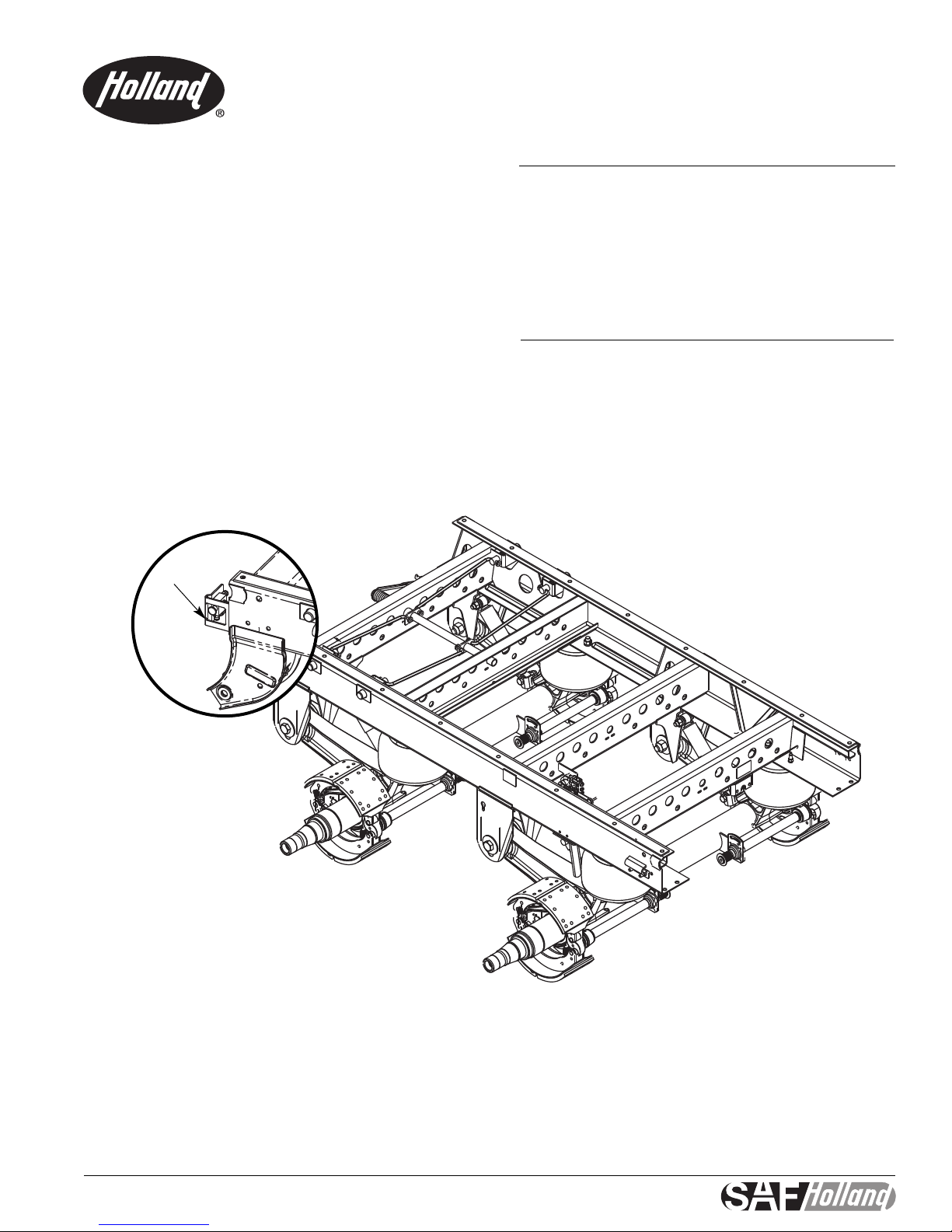
INTRODUCTION
This manual provides you information necessary for the
installation, adjustment, inspection, and safe operation of the
Holland air release feature for Trailer Sliding Suspensions.
No more pulling. New Air release effectively retracts and engages
slider pins with the pull/push of a knob. For added simplicity,
the Air Release operates with a proven design air brake chamber
just likecurrent braking systems.
No training is required and faster slide relocation is enabled by
the simple switch operation.
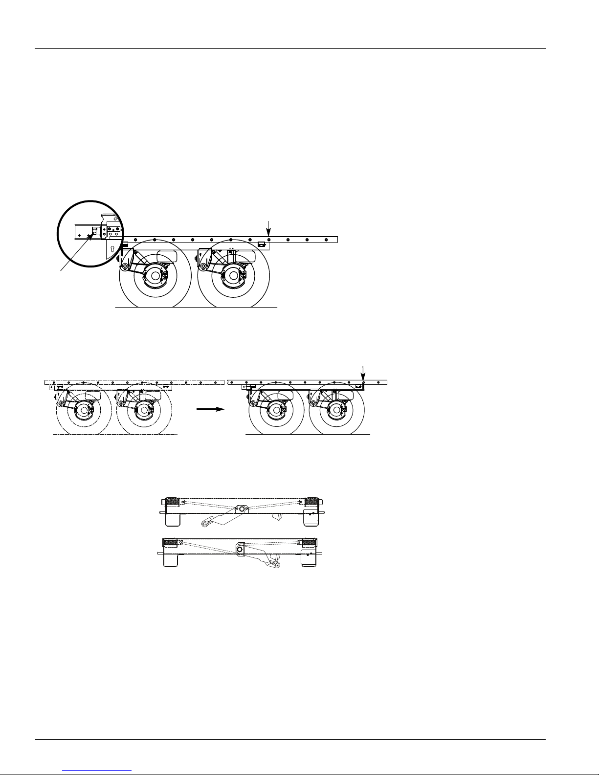
To adjust the slide, the driver must park on level ground and set
all the brakes.The driver reloactes the stop bar to the desired
location and pulls out the Air Release knob located on the front
of the slider. The air brake chamber then releases the pins and
locks in the out position to allowmovement.When pins have
released the driver slowly repositions the tractor until slide
contacts the manual stop bar. Set tractor brakes after positioning
is complete. Push in the knob and pins automatically engage and
lock into place.
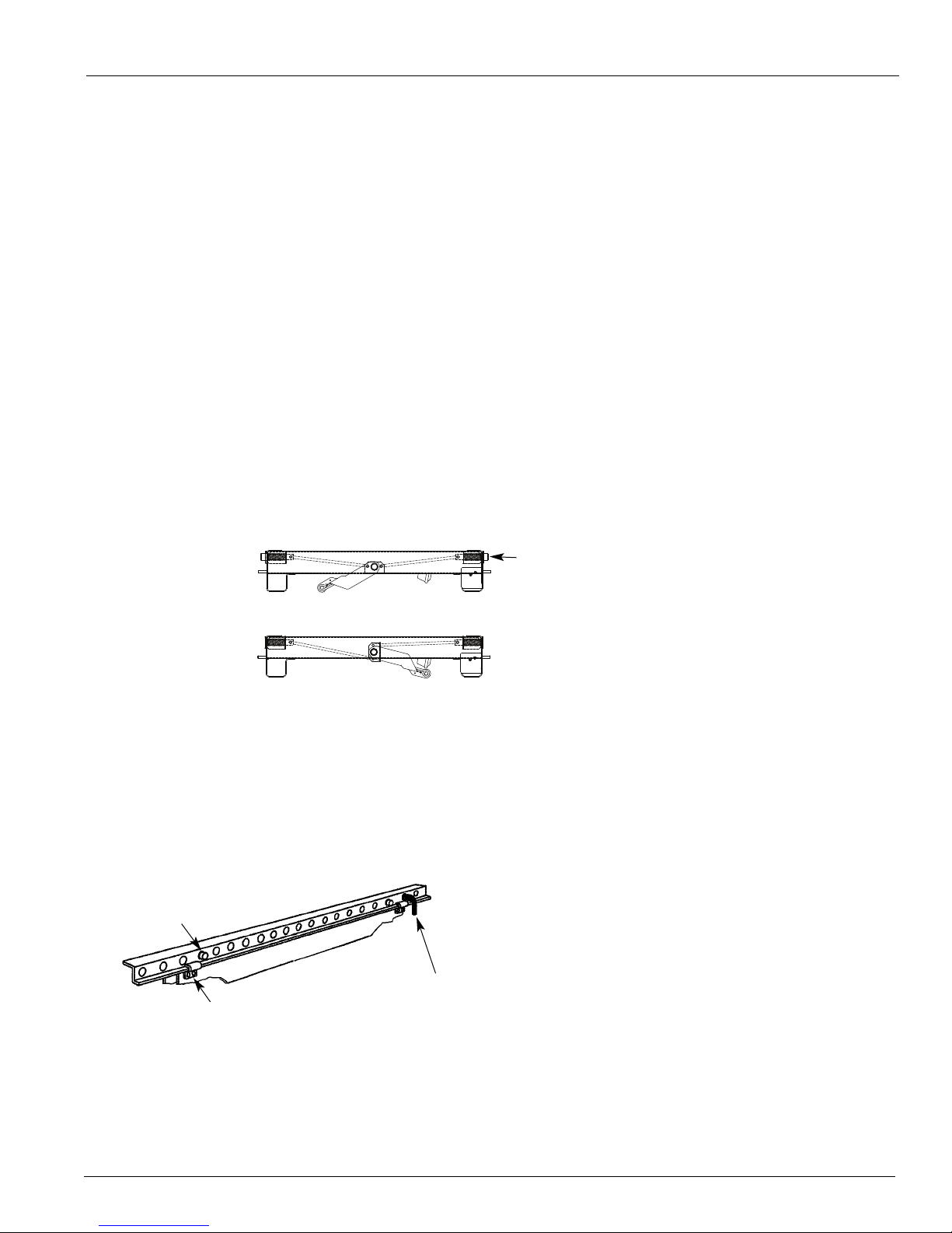
The driver must check to ensure lock pins extend through upper
rail.As an added measureof safety, the stop bar must be relocat-
ed 1 hole behind slider before operating the vehicle.
For added driver safety, the Air Release only works when the
parking brake is set and is connected to the air supply with a
valve to prevent draining.
Air Release is available on all models of Holland slides - new and
retrofit. Optional manual back up also is available.
WARRANTY
Refer to the complete warranty for the country in which the
product will be used.A copy of the written warranty is included
with the product as well as in the suspension catalogs and on
the Holland Group Web Site (www.safholland.us).
It may also be ordered directly by calling 1-888-396-6501.
NOTES, CAUTIONS,
AND WARNINGS
You must read and understand all of the safety procedures
presented in this manual before starting any work on
the suspension.
Proper tools must be used to perform the maintenance and
repair procedures described in this manual. Many of these
procedures require special tools.
Failure to use the proper equipment could result in
personal injury and/or damage to the suspension.
Safety glasses must be worn at all times when
performing the procedures covered in this manual.
Throughout this manual, you will notice the terms “NOTE,”
“IMPORTANT,”“CAUTION” and “WARNING” followed by impor-
tant product information. So that you may better
understand the manual, those terms are as follows:
NOTE: Includes additional information to enable accurate
and easy performance of procedures.
IMPORTANT: Includes additional information that
if not followed could lead to hindered
product performance.
Used without the safety alert symbol,
indicates a potentially hazardous situation
which, if not avoided, may result in
property damage.
Indicates a potentially hazardous situation
which, if not avoided, may result in minor
or moderate injury.
Indicates a potentially hazardous situation
which, if not avoided, could result in death
or serious injury.

XL-AR452 Rev. C 3
INSTALLATION PREPARATIONS
1. For ease of installation of the Air Release Kit, it is advisable
to remove the slider/suspension from under the trailer.
Follow the trailer manufacturer’s slider/ suspension removal
procedures or the suspension maintenance manual for the
safe removal of the slider/suspension.
2. If the trailer was equipped from the factory with an Air
Release, refer to FIGURE 1 and FIGURE 2 for the
appropriate configuration and location.
INSTALLATION
The following instructions will provide you with the necessary
information to accurately install the Air Release System on
your slider/suspension.
1. After the slider/suspension is out from under the trailer,
refer to Steps 2 – 6 for proper bracket locations.
NOTE: The pull handle must be removed from the slider
frame prior to the Air Release installation.
2. For a CB400/4000 suspension locate the actuator chamber
bracket and weld in place as shown in FIGURE 3. For a
mechanical suspension locate the actuator chamber bracket
as shown in FIGURE 4.
3. Locate the Spring Brake Cam as shown in FIGURE 3 and
FIGURE 3A for the CB400/4000 and tack weld in place. If
you have a Mechanical Suspension, refer to FIGURE 4 and
FIGURE 4A.
NOTE: The spring brake actuator rod and clevis should be
horizontal when attached for the CB400/4000
Suspension. Pay close attention to the spring brake
cam angle prior to finish welding.The cam pin must
be lower than the tube for ease of rotation proper
cam stroke for CB400/4000 suspension.
FIGURE 1
Air Ride Slider/Suspension (CB4000)
SLIDER - TOP VIEW
FIGURE 2
Mechanical Slider/Suspension (UltraLite 2)
SLIDER - TOP VIEW
FIGURE 3
Welding Actuator Chamber Bracket
(Air Ride CB Suspension)
ACTUATOR
CHAMBER
3.45˝
0.19˝
9.40˝ ±0.06˝
ACTUATOR CHAMBER
MOUNTING BRACKET
FRONT CROSSMEMBER
FIGURE 3A
Welding Actuator Chamber Cam Bracket
(Air Ride CB Suspension)
CAM
BRACKET
3.25˝
TORSION
CAM
PIN PULL
ROD
LOCK PIN
TORSION
CAM
PIN PULL
ROD
PIN PULL
ROD
ACTUATOR
CHAMBER
LOCK PIN LOCK PIN
ACTUATOR
CHAMBER
TOP VIEW FRONT VIEW
CAM
BRACKET
CAM
BRACKET
0.19˝,
2 PL
68º
CLEVIS

4XL-AR452 Rev. C
INSTALLATION continued
FIGURE 4A
Welding Actuator Chamber Cam Bracket (Mechanical Suspension)
0.16˝
FIGURE 4
Welding Actuator Chamber Cam Bracket (Mechanical Suspension)
10°
0.77˝
0.19˝
33°
4.49˝
0.19˝
BOTH
SIDES
MIDDLE CROSSMEMBER
COMPRESSION SPRING
4. For the Mechanical Suspension notice the Actuator
Chamber Bracket is at an angle and the Spring Brake Cam is
located with the cam pin location on the top of the
Torsion Cam Tube.
5. Locate the Valve Bracket as shown in FIGURE 5
and FIGURE 6.
NOTE: For air release without stinger mounting bracket.
6. Install the Actuator Chamber and male connector.Torque all
air chamber 1/2˝, mounting bracket nuts to 50 - 60 ft. lbs.
7. Install the Air Release Control Valve. Refer to the Air Release
Plumbing Diagram for proper plumbing (FIGURE 7).
FIGURE 5
Locating Valve Bracket
FIGURE 6
Locating Valve Bracket
0.19˝
MOUNTING
BRACKET
0.25˝
1.63˝ +0.00 -0.06˝
HOLE MUST BE
FREE OF WELD
SPATTER
0.50˝ +0.00˝ -0.06˝
0.25˝
0.25˝ 3.25˝
0.50˝ ±0.06˝
NOTE: For air release with stinger mounting bracket.
3.25˝
SEE
FIGURE 4

5
XL-AR452 Rev. C
FIGURE 7
Air Release Plumbing Diagram
AIR TANK
RESERVOIR
to supply
(emergency)
gladhand
LOCK PIN
RELEASE ACTUATOR
AIR RELEASE
CONTROL VALVE
PRESSURE
PROTECTION
VALVE
RESET
CYL
N.C.
Plumbing Connections
VALVE PORTS PLUMB TO
CYL Pin release actuator
RESET Supply line (emergency)
N.C. Air tank reservoir
PULL to Disengage
PUSH to Engage
TO CAM ON
TORSION CAM TUBE
PLUMBING DIAGRAM
Air Release Retrofit Kit Parts - SPK-0055
SPK-0055
HOLLAND
ITEM DESCRIPTION PART NO. QTY.
1 Bracket, Valve 900 26 223 1
2 Cam, Spring Brake 900 45 547 1
3 Bracket, Spring Brake 900 26 227 1
4 Push, Pull, 3/2 with Air Pilot Reset 905 60 012 1
5 Spring Brake Service Chamber 9 905 48 040 1
6Connector, Male, Push Connect 938 00 329 1
7 Literature Decal XL-AR429 1
8 Retrofit Air Release Installation Drawing SL0A1457 1
9 Air Release Plumbing Diagram XL-AR438 1
PARTS LIST
MALE
CONNECTOR

6XL-AR452 Rev. C
OPERATING INSTRUCTIONS
Operating instructions to reposition sliding tandems:
1. Do the following:
•Park on level ground.
•Set all brakes.
• Exit cab and locate slider Air Release control valve.
• Remove slider manual stop bar.
•PULL knob on the Air Release control valve.
NOTE: This will disengage the lock pins in the body rails.
2. Position manual stop bar at desired location.
NOTE: Stop bar should be located one hole foreor aft of
desired position.
3. Visually check to ensure the lock pins are disengaged or in
the pins “out” position.
4. If lock pins release, proceed to Step 6.
NOTE: If lockpins do not release, proceed to
Step 5 procedure.
CURRENT SLIDER/SUSPENSION
POSITION DESIRED SLIDER/SUSPENSION
LOCATION
MANUAL
STOP BAR
LOCK PIN
AIR RELEASE KNOB
MANUAL
STOP BAR
REMOVED
PINS “IN”
ENGAGED POSITION
PINS “OUT”
DISENGAGED POSITION

XL-AR452 Rev. C 7
LOCK PINS ENGAGED
IN SLIDER RAIL
FRONT OF
TRAILER
REPOSITIONED
MANUAL STOP BAR
6. When pins have released – slowly reposition tractor until
slide contacts the manual stop bar.
7. Do the following:
• Set tractor brakes after slide has been repositioned.
• Trailer parking brakes should still be engaged.
• Exit caband walk back to slider.
•PUSH the Air Release control knob to engage the pins.
8. Do the following:
•Check to ensure lock pins extend through upper rail.
•As an added measureof safety, the stop bar must be
relocated 1 hole aft of slider before operating
the vehicle.
• After finishing the walk around safety check, you are
ready to drive. Remember, always check that the lock
pins arethrough the holes in the upper rail.
OPERATING INSTRUCTIONS continued
5. Do the following:
• Be certain the vehicle is clear of people
and obstructions.
• Release tractor brakes only.
• Gently rock tractor and trailer.
• Listen for pins to release.
NOTE: The air actuator will automatically retract the lock
pins when the pressure on the lock pins is
released.
PINS “IN”
ENGAGED POSITION
PINS “OUT”
DISENGAGED POSITION
SLIDE BOX LOCKED IN PLACE
SLIDE BOX CAN MOVE
LOCK PINS ENGAGED
IN SLIDER RAIL

8XL-AR452 Rev. C
Engineering Your Road to Success
www.safholland.us
Copyright © May 2008-SAF-HOLLAND, Inc. All information contained in this document was correct at time of copyright, and is subject to change without notice. All rights reserved.
SAF-HOLLAND USA, Inc. SAF-HOLLAND Canada Limited
888.396.6501 Fax 800.356.3929 519.537.3494 Fax 800.565.7753
Western Canada
604.574.7491 Fax 604.574.0244
Table of contents
Other Holland Automobile Accessories manuals
Popular Automobile Accessories manuals by other brands

Muth Mirror Systems
Muth Mirror Systems Signal installation instructions

Rola
Rola PMX194 Fitting instructions

Gewiss
Gewiss JOINON Column Installation and operation manual

Rostra
Rostra RearSight 250-8800-LPB installation instructions

Gembird
Gembird BTT-05 user manual

Safe Fleet
Safe Fleet PRIME DESIGN VRR-CE11B manual

Thule
Thule Railing Load Carrier 754 installation instructions

Performance Accessories
Performance Accessories 843 manual

Roadmaster
Roadmaster 88336 installation instructions

Alpine
Alpine KTX-CMO installation manual

Fiamma
Fiamma ROLLO VENT 50 Installation and usage instructions

AutoMaxi
AutoMaxi SILVER Line KIT FIX 020 instructions