Holland FW0E70-02 User manual

Fifth
Wheel
Operating
Manual
FWOE70-02
FW0E70-03
Table of Contents
1 Component Part Identification and Specifications
1.1 Identification of component parts . . . . . . . . . . . . . . . . . . . . . . . . . .
1.2 Important specifications . . . . . . . . . . . . . . . . . . . . . . . . . . . . . . . . . .
Page
2 Operating Instructions
2.1 Pre-service inspection . . . . . . . . . . . . . . . . . . . . . . . . . . . . . . . . . . .
2.2 Trailer coupling procedures . . . . . . . . . . . . . . . . . . . . . . . . . . . . . . .
2.3 Trailer uncoupling procedures . . . . . . . . . . . . . . . . . . . . . . . . . . . . .
3 Routine Inspection and Maintenance
3.1 As Needed Lubrication . . . . . . . . . . . . . . . . . . . . . . . . . . . . . . . . . . .
3.2 Required Inspections and Adjustments . . . . . . . . . . . . . . . . . . . . . .
3.2.1 General fifth wheel inspection . . . . . . . . . . . . . . . . . . . . . . . . . . .
3.2.2 Inspection of locking mechanism . . . . . . . . . . . . . . . . . . . . . . . .
3.2.3 Lock adjustment procedure . . . . . . . . . . . . . . . . . . . . . . . . . . . . .
XL-FW1083-01
1
WARNING
You must read and understand the instructions in this manual
before operating your fifth wheel.
Failure to follow all of the important operating procedures
contained in these instructions may result in a dangerous condition
or cause a dangerous condition to develop.
These instructions apply to the proper operation of your fifth wheel
only. There are other important checks, inspections, and
procedures not listed here that are necessary, prudent, and/or
required by law.
Fifth Wheel
Operating Manual
2
2
3
4-5
5-6
6
7
7
8

1 Component Part Identification and Specifications
1.1 Identification of component parts
1.2 Important specifications
XD-71-D-E
14 Adjusting
Wedge
15 Bolt
16 Nut
17 Spring
13 Locking
Plunger
9 Secondary
Lock Pin
10 Grease
Fitting
11 Cotter pin
6 Secondary
Release Handle
3 Lock Jaw Pin
4 Retaining Ring
5 Grease Fitting
1 Primary
Release
Handle
24 Lock Nut
25 Lock washer
Fixed Front
Lock
18 Locking
Plunger
Spring
19 Release Arm
20 Bolt
21 Washer
22 Bushing
23 Nut
2A, 2B
Swing
Lock
Jaw
Bracket
Pocket
XL-FW1083-01
Part Number Height Weight
Vertical
Load D-Value Locks
FW0E70-03-TP
FW0E70-02-TP
top plate only
top plate only
148 kg
148 kg
3.5"
2"
36000 kg
30000 kg
240 kN
170 kN
FW0E70-03-200
FW0E70-02-200
200 mm
200 mm
184 kg
184 kg
3.5"
2"
36000 kg
30000 kg
240 kN
170 kN
Holland Europe reserves the right, without prior notice, to change specifications and dimensions.
HOLLAND
1033
880
695
510
40°
390 closed
485 open
254442
457
406
17
23
254
200
17
442
2
The load limits given are valid for
operation on paved roads and
under conditions prevailing in
Europe. For alternative conditions,
please consult Holland.
WARNING
Mounting must be carried out in
accordance with Holland instructions.
1
2A
XA-1117-H 1 Release handle, primary
3
XA-FW-104-D 1
4
5 XB-H-38-A
1
6
XB-09153 1
7
1
Lock pin, secondary
8
XA-08783 1
9
RK-65025 1 Secondary lock arm replacement kit
10
XB-16 1 Cotter pin
11
XA-1016-C 1
Locknut ( )
12
XB-0769 1
Socket Head Cap Screw ( )
13
XB-5 1
Release handle assembly, secondary
1
XB-1028-2 Secondary lock spring
1
Locking plunger
14
Grease fitting
Cotter pin
XA-1104
XD-3123-1 1 Adjusting wedge
15
1
XB-09407
16 1
XB-HNH-58-C
NO. PART NO. QTY. PART NAME
17 1Adjusting wedge spring
XB-403
18 1Locking plunger spring (red)
XB-1007
19 1Release arm
XA-1005-FH
Lock set replacement kit for 2,0" kingpin
2B XA-FW-104-03 1 Lock set replacement kit for 3,5" kingpin
5/8"-11
5/8"-11 x 4"
7 Secondary
Lock Arm
8 Cotter pin
12 Secondary
Lock Spring
20 1
XB-2083
21 1Washer ( ")
XB-T-49
22 1Bushing
XB-02949
23 1Locknut ( )
XB-T-69-A
24 1
XB-04473
Grease fitting
Retaining ring
XA-FW-108-D-15 Lock pin, primary
25 1Lock washer (1")
XB-10327
*Lock jaws and adjustment wedge are only sold as a
complete lock set kit and cannot be ordered individually.
Hex Head Cap Screw ( )
1/2"-20 x 1 "
3/4
1/2
1/2"-20
Locknut ( 1" - 14 )
2A, 2B

2 Operating Instructions
Inspect the fifth
wheel mounting Tighten loose fasteners with required torque
Replace missing fasteners
Repair/replace cracked components
Make sure
coupling area
is flat, level and
clear of obstacles
and persons
Lubricate the
fifth wheel-to-
trailer contact
surface with
grease
Tilt ramps down
Make sure the
locks are open
OK
If locks are closed:
1
2 3
4
FIRST, make sure SECONDARY
lock is open:
5 Pull handle straight
out
6 lift up, and hook
handle "tab" on edge
of casting
7 Insert long bar into
lock jaw opening and
pry open lock jaws
2.1 Pre-service inspection
OK
LOCKS CLOSED
TILT
DOWN
LOCKS OPEN
15
SECOND, make sure PRIMARY
lock is open:
6
))))))))))))))
23
))))))))))))))
HOOK HANDLE
"TAB" ON CASTING
))))))))))))))
HOOK "TAB"
ON CASTING
4
XL-FW1083-01 3
To Open
SECONDARY Lock To Open
PRIMARY Lock
PRIMARY
Lock Handle
SECONDARY
Lock Handle
1 grasp and pull inner
handle
2 move handle down
3 pull handle out
4 lift handle up and hook
handle "tab" on outer
edge of casting

2 Operating Instructions
7
89
2.2 Trailer coupling procedures
SLOWLY back into trailer Do a
pull test
WRONG
FIFTH WHEEL
MUST LIFT
TRAILER
➠
➠
FIFTH WHEEL
TILTED DOWN
100 - 150 mm
USE LOW
GEAR
➠
➠
➠
PULL FORWARD WITH TRACTOR
PULL TEST
TRAILER
BRAKES
LOCKED
Adjust trailer height so
fifth wheel will lift trailer
Trailer should contact
fifth wheel 100 - 150 mm
behind fifth wheel
bracket pin.
➠
➠➠
FIFTH WHEEL
WILL NOT LIFT
TRAILER
Chock trailer wheels
Connect brake
lines and light cord
Support slack in lines
to prevent interference
Set trailer brakes
3
4
5
6
XL-FW1083-01 4
Center kingpin
with fifth wheel
center
Back tractor
close to trailer
and STOP.
TRAILER
(top)
KINGPIN
11 2
The coupling procedure is not complete without a visual inspection. You
must get out of the tractor and verify that the fifth wheel is properly coupled.
Proceed to Step 10 on the following page for visual inspection procedures.
WARNING

2 Operating Instructions
2.3 Trailer uncoupling procedure
2.2 Trailer coupling procedures (continued)
11 Retract landing
gear until pads
come off the
ground
Re-check brake lines and light cord. Remove wheel chocks, continue with pre-trip inspection.
Switch to
high gear,
fully retract,
then secure
crank handle
12
Secure
handle
13
4
Position tractor and trailer on firm, level
ground clear of obstacles and persons
Set trailer brakes
Slowly back tractor
tightly against trailer
Set tractor brakes
Chock trailer wheels
5
3
2
1
1
10 Visual inspection
Get out of tractor
Visually check
that the fifth
wheel is locked
1 - 2 - 3
Failure to properly couple and inspect this fifth wheel could result in
tractor and trailer separation causing death or serious injury to others.
If you do not obtain a proper couple, repeat the coupling procedure.
➠
12
DO NOT USE ANY FIFTH WHEEL THAT FAILS TO OPERATE PROPERLY!
OK
LOCK
JAW
CLOSED
SECONDARY LOCK
HANDLE GUIDE
NO GAP BETWEEN
FIFTH WHEEL AND
TRAILER PLATE
3
SECONDARY HANDLE
LOCK NOTCH ENGAGED
BEHIND GUIDE OF CASTING
WARNING
USE
LOW
GEAR!
XL-FW1083-01 5

3 MAINTENANCE PROCEDURES
3.1 As needed lubrication
NOTE: Maintain adequate lubrication on the following surfaces by inspecting and
re-lubricating at regular intervals. Use a water-resistant, lithium grease.
LOCKING PLUNGER
SLIDING AND
ENGAGEMENT
AREAS
GREASETHETRAILER
CONTACTSURFACE
GREASE
BRACKET
SUPPORTS
THROUGH
FITTINGS (x 2)
LOCK PIN
GREASE
FITTINGS
SLIDING
HANDLE
BAR
and
SPRING
LOCK JAWS
(kingpin
contact areas)
11
6Extend landing
gear until pads
just touch
the ground
Switch to
low gear
and crank an
additional
4 - 8 turns
7
USE
LOW
GEAR!
Secure
handle
Unlock fifth wheel.
First open secondary lock:
8
2.3 Trailer uncoupling procedure (continued)
USE
HIGH
GEAR
1grasp and pull inner
handle
2move handle down
3pull handle out
4lift handle up and hook
handle "tab" on outer
edge of casting
11
2
))))))))))))))
23
))))))))))))))
HOOK HANDLE
"TAB" ON CASTING
))))))))))))))
HOOK "TAB"
ON CASTING
4
To Open
Secondary Lock
To Open
Primary Lock
Second, open primary lock:
1pull handle straight out
2lift handle up and hook
handle "tab" on outer
edge of casting
XD-71-D-E
XL-FW1083-01 6

WARNING
NOTE: Perform the following every three (3) months or 50,000 km, whichever comes
first. Thoroughly steam clean all components before inspecting or adjusting.
3.2.2 Inspection of Locking Mechanism
Verify the proper operation of the fifth wheel by locking and unlocking the
fifth wheel locks using Holland Kingpin Lock Tester TF-TLN-1000 or
TF-TLN-5001.
After each attempt, verify that the fifth wheel is properly
locked as shown below.
TO
LOCK
TO
UNLOCK
Set tool on fifth wheel
and rotate handle Push down and rotate the
"J" hook under the fifth wheel,
then pull handle back
1
23
4
3.2 Required Inspections and Adjustments
NOTE: Perform the following every three (3) months or 50,000 km, whichever comes
first. Thoroughly steam clean all components before inspecting or adjusting.
3.2.1 General Fifth Wheel Inspection
Inspect the
fifth wheel
mounting
and
fifth wheel
assembly
Tighten loose bolts
and fasteners with
required torque
•
Replace missing
or damaged bolts
Replace bet, worn,
or broken parts
Use only genuine Holland parts kits
XL-FW1083-01 7
If you do not obtain a proper couple, repeat the coupling sequence.
DO NOT USE ANY FIFTH WHEEL THAT FAILS TO OPERATE PROPERLY.
•
•

3 MAINTENANCE PROCEDURES
3.2 Required Inspections and Adjustments
3.2.3 Lock Adjustment Procedure
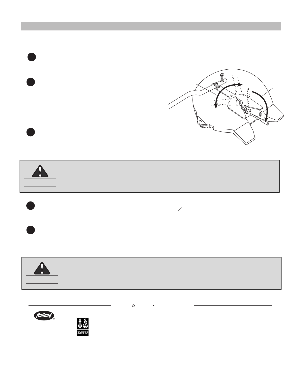
2Using a socket wrench with a 1/2" Allen hex
bit socket, tighten the lock by turning the lock
adjustment bolt clockwise 1/4 turn at a time.
Remove the socket wrench from the bolt
and rotate the tool as shown to check for
resistance between the tool and lock.
TIGHTEN
ROTATE
TOOL
3Continue to alternate tightening (clockwise)
the adjustment bolt 1/4 turn at a time, until the fifth
wheel lock is tight against the kingpin in the lock tester.
4Loosen the adjustment bolt (counter-clockwise) 1 turns.
The lock is now properly adjusted.
5Verify the proper adjustment by locking and unlocking the fifth wheel several times
with the lock tester. On each attempt, make sure the locks properly engage.
1Using Holland TF-TLN-5001 Lock Adjustment Tool, lock the fifth wheel and verify
that it is closed as shown in Step 10 on Page 5.
12
XL-FW1083-01 8
WARNING
At this point the fifth wheel is OVER-ADJUSTED and NOT usable.
The remaining adjustment procedures must be completed.
WARNING
Improper adjustment can cause improper locking of the fifth wheel.
If the fifth wheel does not operate properly, DO NOT USE IT!
Repeat the adjustment procedures or contact Holland.
Copyright June 2004 The Holland Group Inc.
Holland Europe GmbH
Altenkamp 9
D-33758
Schloss Holte-Stukenbrock
Germany
Phone: +49 (0) 5207-89560
Fax: +49 (0) 5207-895656
Holland Eurohitch Ltd.
Hoo Farm Industrial Estate
Worcester Road
Kidderminster
Worcestershire
DY11 7RA
Phone: +44 (0) 1562-732010
Fax: +44 (0) 1562-732020
Holland Transtrade
Far East SDN BHD
Shah Alam, Malaysia
Phone: 60 (0)3 734-2888
Fax: 60 (0)3 736-5588
The Holland Group, Inc.
Holland, MI 49423
United States
Phone: (616) 396-6501
Fax: (616) 396-1511
Holland Transtrade
(Thailand) Company, Ltd.
Bangkok, Thailand
Phone: 66 (0)2-513-8758
Fax: 66 (0)2-513-8757
Nippon Holland, Ltd.
Tokyo, Japan
Phone: 81-(0)3-3461-9130
Fax: 81-(0)3-3463-1407
Holland Hitch (Aust.) Pty. Ltd.
Melton, Victoria, Australia
Phone: 61-(0)3-9743-6799
Fax: 61-(0)3-9747-9617
EN ISO
9001:2000
Certified
Company
This manual suits for next models
1
Table of contents
Other Holland Industrial Equipment manuals
Popular Industrial Equipment manuals by other brands

GBC
GBC CombBind C800pro instruction manual

Moeller
Moeller PS 4 Overview and Engineering Guidelines

Zimmer
Zimmer WWR1000 Series Installation and operating instructions

Jung
Jung eNet FMUD5500REG operating instructions

UTEK
UTEK HRU GUIDE FOR INSTALLATION, USE AND MAINTENANCE

Flexologic
Flexologic FAMM user manual