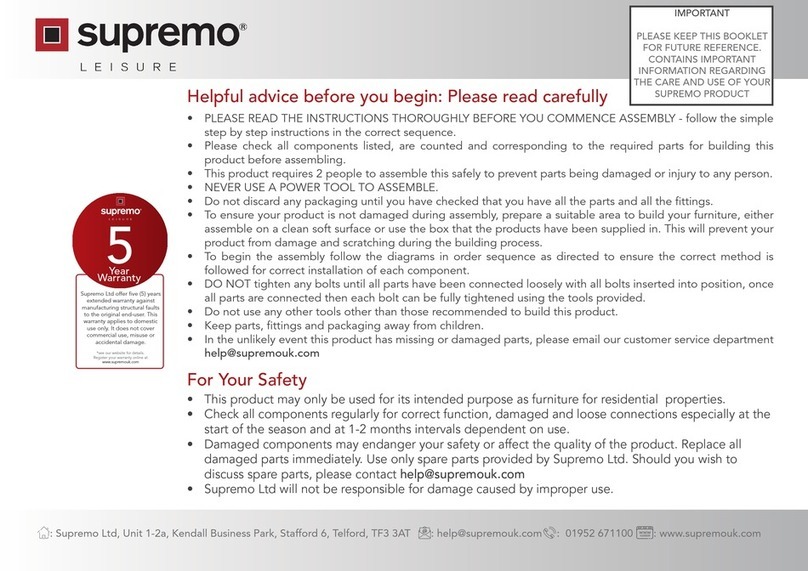
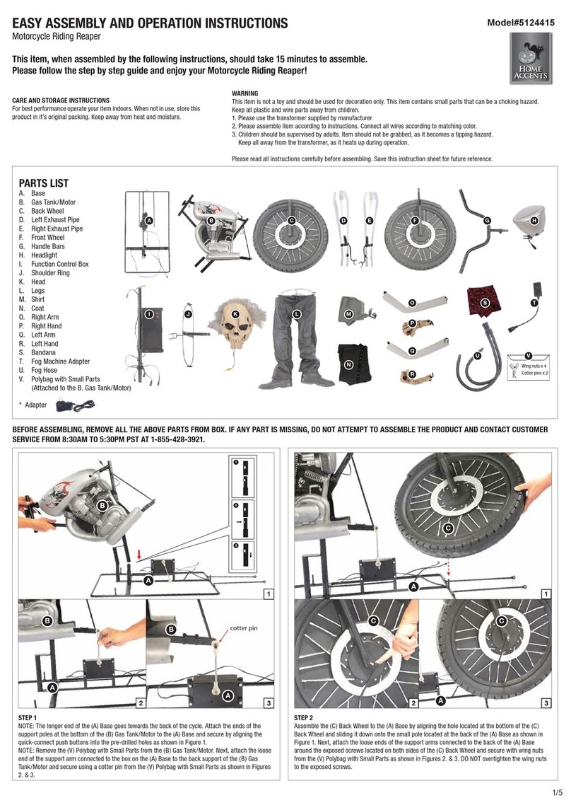
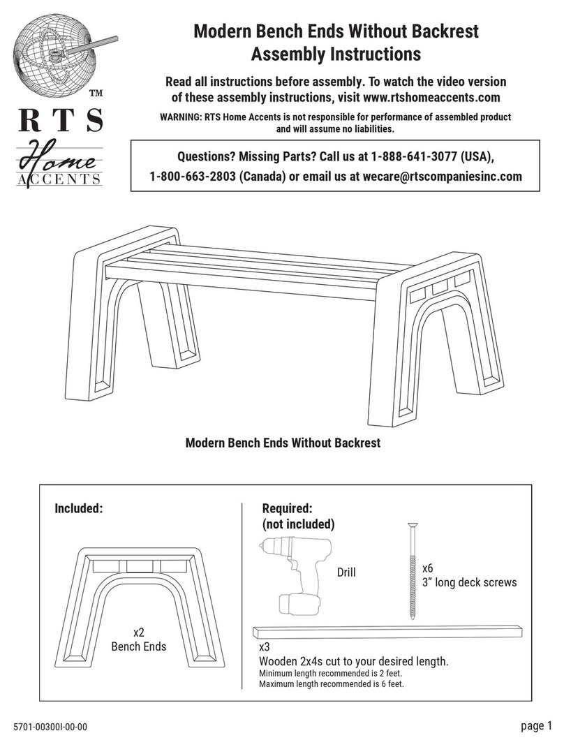
Home Accents Cauldron Witch Parts list manual

STEP 1 STEP 2
1/3
PARTS LIST
A. Base
B. Lower Support Poles x 2
C. Upper Support Poles x 2
D. Torso Frame
E. Hip Hoop
F. Shoulder Support
G. Head
H. Costume
I. Right Arm
J. Left Arm
K. Cloak
L. Hat
M. Cauldron
N. Cauldron Support Poles x 6
O. Cauldron Light Support Frame
P-1. Top Stir Stick
P-2. Middle Stir Stick
P-3. Middle Stir Stick
P-4. Middle Stir Stick
P-5. Middle Stir Stick
P-6. Lower Stir Stick
UL Adapter *
* UL Power Adapter Spec
Input: 100 - 240VAC 50/60Hz
Output: 5.9V 1.5A
A B C D E F G
HI J K L
M N O P-1 P-2 P-3 P-4 P-5 P-6
NOTE: The longer end of the (A) Base goes towards the front. First, secure the (B) Lower Support
Poles to the (A) Base by aligning the quick-connect push buttons into the pre-drilled holes. Then
set the cross-braces located at the (A) Base into the slot housings on the (B) Lower Support
Poles as shown in Figure 1.
Assemble the (C) Upper Support Poles to the (B) Lower Support Poles as shown in Figure 2, and
secure by aligning the quick-connect push buttons into the pre-drilled holes.
E
D
EASY ASSEMBLY AND OPERATION INSTRUCTIONS
Cauldron Witch
This item, when assembled by the following instructions,
should take 15 minutes to assemble. Please follow the step
by step guide and enjoy your Cauldron Witch!
Model#5124417
Sensor / Détecteur
5.9V
Note: Do not plug the UL Power Adapter into
power outlet until item assembly is completed.
OPTIONAL: If you choose to use the Step Here
Try-Me Activation Pad, plug the connector into
the input receiving jack marked “TRY ME” on the
Function Control Box and set the Step Here pad
in front of the character when ready to display.
STEP
HERE
UL
ADAPTER
(Not included)
Try me / Essaie-moi / Pruébame
B
CC
B
B B
AA
1
2
3
1 2
E
D
C C
2
1
NOTE: The speaker on the Function Control Box located on the (D) Torso Frame should be facing
front.
Attach the (D) Torso Frame on top of the assembled (C/B) Support Poles as shown in Figure 1, and
secure by aligning the quick-connect push buttons into the pre-drilled holes.
Attach the (E) Hip Hoop through the slots located on the (D) Torso Frame as shown in Figure 2.
Plug the Adapter into the input DC 5.9V on the function control box.
WARNING
This item is not a toy and should be used for decoration only. This item contains small parts that
can be a choking hazard. Keep all plastic and wire parts away from children.
1. Please use the transformer supplied by manufacturer.
2. Please assemble item according to instructions. Connect all wires according to matching
color.
3. Children should be supervised by adults. Item should not be grabbed, as it becomes a tipping
hazard. Keep all away from the transformer, as it heats up during operation.
Please read all instructions carefully before assembling. Save this instruction sheet for future
reference.
CARE AND STORAGE INSTRUCTIONS
For best performance operate your item indoors. When not in use, store this product in it’s
original packing. Keep away from heat and moisture.

STEP 3
STEP 4
STEP 5
2/3
J
D
G
F
I
Attach the (F) Shoulder Support into the slots located on the top of the (D) Torso Frame as shown in
Figure 1.
Set the (G) Head onto the (D) Torso Frame by sliding the forked-hook into the “neck” slot housing on
the (D) Torso Frame as shown in Figure 2.
Connect the cables from the (G) Head to small function box loacted the (D) Torso Frame as shown in
Figure 3.
Lower the (H) Costume down over the Head (G) & assembled (F) Shoulder Support as shown in
Figure 1.
Secure the hook & loop closures at the neck and inside collar as shown in Figure 2.
Slide the (I) Right Arm up through the Right sleeve of the (H) Costume and slide the forked-hook into
the right “shoulder” slot housing on the (D) Torso Frame as shown in Figure 1.
Slide the (J) Left Arm up through the Left sleeve of the (H) Costume and slide the forked-hook into
the left “shoulder” slot housing on the (D) Torso Frame as shown in Figure 2.
Secure the hook & loop closures at both wrists as shown in Figures 3.&4.
Make sure the circles of Arm joints don’t overlap and attach the arms from the front of the Witch as
shown in Figure 5.
STEP 6
HH
K
L
Back
Front
Back
Front
Locate the hook & loop closures at the back of (H) Costume as shown in Figure 1.
Set the (K) Cloak onto the shoulder of witch. Secure under the chin and at the back with the hook
and loop closures as shown in Figure 2.
Attach the (L) Hat onto the (G) Head, and secure the hats with the hook & loop closures at the
forehead and inside of the hats as shown in Figure 3.
H
K
GL
G
H
F
G
G
D
D
1
2
3
G
H
D
H
21
G
DJ
ID
I
J
1
3
13
2
2
4
5

3/3
STEP 8
STEP 9
NOTE: The Stir Stick has size-specific connections and can only be assembled one way.
First, slide the (P-2) Middle Stir Stick down through the hole in the hand of the (I) Right Arm as
shown. Then, slide the (P-3) Middle Stir Stick up through the hole in the hand of the (J) Left
Arm, and twist counter-clockwise to secure. Then attach the (P-1) Top Stir Stick to the top of
the (P-2) Middle Stir Stick, assemble the (P-3)&(P-4)&(P-5)) Middle Stir Sticks to each other to
the (P-6) Lower Stir Stick as shown. Next, set the (P-6) Lower Stir Stick into the mechanism
located on the (M) Cauldron as shown.
A2
A2
A3
A3
A1
A1
M
A
A
Set Assembled (M) Cauldron onto (A) Base by attaching the slots located at the front of (A) Base as
shown.
Connect A1, A2, A3 cables from the (M) Cauldron to the coordinating cables from the Function control
box on (D) Torso Frame through the (H) Costume.
STEP 7
Insert the tips of each flexible support rod
into the fabric slots sewn to the inside of
the Cauldron
M
M
N
Slot
Sensor
Elastic Band
O
O
Assemble the (M) Cauldron by sliding the ends of each (N) Cauldron Support Poles into the fabric
pouches found at the top and bottom of the inside of the cauldron as shown in Figure 1.
Attach the top center of the (O) Cauldron Light Support Frame on the top of the cauldron using
elastic band as shown in Figure 2.
Insert Poles of the (O) Cauldron Light Support Frame into the slots located on the cauldron base as
shown in Figure 3.
NOTE: Sensor located at the front of
cauldron under the (O) Cauldron Light
Support Frame.
M
P-6
P-5
P-4
P-3
P-2
P-1
I
I
J
J
OPERATION INSTRUCTIONS:
1. Plug the Adapter into a standard power outlet and adjust the settings on the Function Control Box,
located on the (D) Torso Frame , as desired.
2. Settings:
Sensor : This switch mode will only activate lights, sound, and animation when the Infra-red (IR) sensor
is activated. The item will operate for 1 audio-cycle with each sensor activation. The Infra-red
(IR) sensor will activate when someone comes within an 80-degree angle from left-to-right, as
well as from above and below. The Infra-red (IR) sensor has a range of up to 2 m / 6.5 ft.
: OFF - This switch mode will turn the lights, sounds, and animation off.
I : ON - This switch mode will continually operate the lights, sound, and animation of the item.
: Raise or lower the volume using the volume control turn dial, turn and click all the way down to
turn the volume off.
This device complies with Part 15 of the FCC Rules. Operation is subject to the following two conditions: (1) This device may not
cause harmful interference, and (2) this device must accept any interference received, including interference that may cause
undesired operation.
CAUTION: Changes or modifications not expressly approved by the party responsible for compliance could void the user’s
authority to operate the equipment.
NOTE: This equipment has been tested and found to comply with the limits for a Class B digital device, pursuant to Part 15 of the
FCC Rules. These limits are designed to provide reasonable protection against harmful interference in a residential installation.
This equipment generates, uses and can radiate radio frequency energy and, if not installed and used in accordance with the
instructions, may cause harmful interference to radio communications. However, there is no guarantee that interference will not
occur in a particular installation. If this equipment does cause harmful interference to radio or television reception, which can be
determined by turning the equipment off and on, the user is encouraged to try to correct the interference by one or more of the
following measures: Reorient or relocate the receiving antenna, Increase the separation between the equipment and receiver,
Connect the equipment into an outlet on a circuit different from that to which the receiver is connected. Consult the dealer or
experienced radio/TV technician for help.
CAN ICES-3 (B)/ NMB-3 (B)
Sensor / Détecteur
5.9 V
Try me / Essaie-moi / Pruébame
1
2
3
Other Home Accents Outdoor Furnishing manuals
Popular Outdoor Furnishing manuals by other brands

PHI VILLA
PHI VILLA PV-097 Use and care guide

Sunjoy
Sunjoy A106008100 Assembly instruction

Sunjoy
Sunjoy Royal Hardtop Gazebo quick start guide

Uberhaus
Uberhaus 79275038 Operator's manual

Target
Target Threshold 009050409 Assembly instructions

Forever Redwood
Forever Redwood HANNELL WOODEN GARDEN BENCH Assembly instructions

Forever Redwood
Forever Redwood ENSENADA WOODEN ROCKING CHAIR Assembly instructions

Sunjoy
Sunjoy STONEBORO L-GZ098PST-1D Assembly instruction

Outsunny
Outsunny 84B-771 manual

Dorel Home Products
Dorel Home Products 2261659 manual

sweeek.
sweeek. BOHEMIA AC3101CAN manual

Fortress Building Products
Fortress Building Products H Series installation instructions