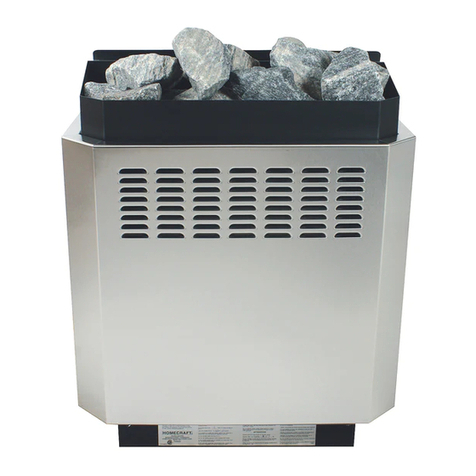
Homecraft CHSH 4 Assembly instructions

!"# $ " % ! # "" ! % $& % ' # !!( # )& * $& % * + % & "% ,
# "" & # "!) % !# % & + - ,./.
-./,0 /-!0
.12 - .12 .
2 -3 /2 -
4.0/-+ 2 /
54 -
Note: no combustible materials are permitted under the heater. Examples: duckboard flooring, towels, paper towels,
etc.
!
666 768769 : :-;8:<-7 =6 :6
666 768769 : 76-987 =6 :6
666 768769 : 7879-< 6 9
=" ' :6 76 ;9>
" ' 7 76 =66 ;9>
=" ' :66 :6 ;9>
"
#
"
Last edited January 6, 2007
$:-
15.00"
1.00"
8.00"
CHSH side view
12.00"
22.00"
1.00"
CHSH corner mount
1.00"

$7-
$=
- "
7- $ %
!?2 00
2 ,
..,-
2 2 /2 .-
* -
?
7# - 2 .
$=-
7'-" /,
2 0.2 -% ,
,
-
-& .2
-
7-
2 .
. -$.
0-
!?. 2 2 5/-! & ,
& )& % )& # & $"% # & % !3 & % -
73 - 2 2 .2 ,
.0-../2 ,
-
7& '''- $
.-
Temperature
Sensor
WallControl
FromBreaker
Panel
RelayControl
Box
Suggestedposition,
Refertonote#7
24.00"
12.00"3.00"
HSH side view
4.00"
20.00"
12.50"
HSH top view

$-
7$-# 0..@>
-3 2 /02 2 .
- 2 -3 2 ,-
=- (
.00,-2 .:7
4/2 - 2 .2 ,
2 -3 0-% /2 2
./2 - /:760
2 /-
- )*
# 2 02 / 002 .1
A. - 2 .2
/ .// 2 2
.2 -@/ >5/5
02 2 /-
- * $
!0 /52 .0-# /.
-
.
2 .
2 .
Sensorposition
2-1/2"belowceiling
7" 21"
29"
23"fromwallmaximum
Sensorposition
2-1/2"belowceiling
8-3/4"
8-3/4"
25" 25"
Wall brackets
13"maximum
Sensorposition
2-1/2"belowceiling
16"maximum
3.50"
14.00"
25"

- $ &
# 2 & ./-
2 0/.-.
>2 2 2 B1C-+ :>D >7>
D >2 / .0/2 0-
$-
$-
4.00"
4"
4"
28.75"
16.50"
4"
4"
4"
4"
4"
Adjoining wall
4"
4"
1"
12"
20"

;- + %
, $ $ -. $ $ / $ $ 0* .1 231- '
0 ,2 /-
2 //2 -
705( $.-' //-
* 4
5%* * " 5
)
5+ * 5)"")+ ")
5'* )
+ 57,.1 ,2 - .1.
2 -# 2 2 .2 ,
-
2 ?:C@/.1>702
/7C@ ,2 >2 7,.1B C./
//2 2 =C 2 ,
..2 2 5-
9- & ) #
@/.1>702 /2 .1- /
.1.2 2 - .1.2 /
0.5-E/2 /2 ,
/.1B71C - //2 /
/.1-# 2 /.1
0 ..0
-
!:7:98 /.1 ,
. -..2 2 =89>
2 /.1- .:98 ..2 2 .1-
# :98 ./
.1-)
.A2 .1-
2 :7// 2 2
:98 /-3 :7:98 -' ,
/. /.1 2 -
<-
@ >.2 ./2 5
- 2 .-
,@8% >
,@$8> . $2 2 12 2 2 ,
:<$B<6C2 ./-

,2 2 /A./.=- 2
.2 12 2 62 -
,/. /-
?2 -3 @1>2 2 .-# 2 .,
-
:6- 6
2 B:7C:987 -/,
5. ./ :987
-3 !% :7 -':987
-7'0:987 -
.>2 :987000-
2 :987 02 1./ /1
. - 2 2 89>,
2 0BC-
3 ./.0 -,
0/2 2 B/0
C2 2 /-
::- '
F 0
.7,:87>. -'2 002 2
0B
$;C
-!10 ,F
0 - 0,
5 -,
2
2 -
$;-
F7:,<,:<7
/' --G !
?:,966,9;6,;?6,999,=6=1?6,999,=:;
48 * "4* * * "
79: 6 + : 9%96 ((6 %: 9%9 ; (% ; 9
2 0102
- 2 00
2 12 2 /02 -
.2 /./@>:987
.- / 0,
:987.-'
2 :987
. /2
-
004/
.2 -
; 6 %: 94..0,
/0//.,
/-

Probe
Probe
24 VAC
24 VAC
Heater
Heater
24 VAC
Class II
Transformer
H2 H1 L2 L1
Breaker Panel
Sauna Heater
24 VAC
24 VAC
Heater
Heater
TKEC wiring diagram, with contactor
Single phase, 208/240 volt controls
Temperature Probe
"position per installation
instructions"
Wall Control (rear view)
Control Circuit
18/4 copper wire
Ground
Ground
18/2 wire
Line out to
sauna heater
This manual suits for next models
3
Table of contents
Other Homecraft Heater manuals