HomePluss ecoPLUS EP-600 Troubleshooting guide

OWNER’S MANUAL & INSTALLATION GUIDE
ecoPLUS™ EP-600
PLEASE READ THIS MANUAL CAREFULLY BEFORE
ATTEMPTING INSTALLATION. FAILURE TO FOLLOW THESE
INSTRUCTIONS MAY AFFECT THE PERFORMANCE OF YOUR
SYSTEM VOID YOUR WARRANTY AND RESULT IN
PROPERTY DAMAGE.
t

2
Congratulations on the purchase of your ecoPLUS™ Series premium whole house water
filtration system.
ecoPLUS™ is specifically engineered to treat city water by removing chlorine, chloramine,
disinfection by-products, bad tastes and odors, and other trace contaminants including
VO s, pesticides, herbicides, organic chemicals, lead, and more. ecoPLUS™ delivers
refreshing, great tasting drinking water, and protects your skin and hair from the damaging
effects of these contaminants.
To get maximum performance from your ecoPLUS™ system, we encourage to read this
manual in its entirely before installation and operation of your filter.
IMPORTANT SAFETY SYMBOLS
Hazards or unsafe practices that may result in personal injury
and/or severe property damage.
Hazards or unsafe practices that may cause operational
problems with your water treatment system.

3
Table of Contents:
GENERAL WARNINGS ……………………………………………………………………………………………...….. …….. 4
OPERATING ONDITIONS …………………………………………………………………………………………….…... 5
INSTALLATION ………………………………………………………………………………………………………….…..…..….. 6
Step 1 – Pre-Installation Inspection ……………………………………………………………..……… 7
Step 2 – Selecting an Installation Location ………………………………………………..…..... 8
Step 3 – Attach Mounting Bracket to Housing ap ………………………………..……… 9
Step 4 – Attach Housing ap to Wall …………………………………………………………………. 9
Step 5 – Install artridge Filter and Attach Sump ……………………………………….…… 10
Step 6 – onnect Outlet Assembly to the Bypass Assembly ……………………..…. 11
Step 7 – onnect the Bypass Assembly to Valve Head ……………………………..….. 12
Step 8 – onnect the Inlet Assembly to the Housing ap ………………………..…… 12
Step 9 – onnect the Bypass to the Inlet Assembly …………………………………..…….. 13
Step 10 – Turn off the Water & Electric Water Heaters ………………………………….… 14
Step 11 – onnect the System to Inlet and Outlet Pipes ………………………………… 15
Step 12 – Initial Start-up and Leak Testing …………………………………………………......…. 16
TROUBLESHOOTING ………………………………………………………………………….……………………….…..…… 18
MAINTENAN E ………………………………………………………………………………….…………………….…..….……. 19
VALIDATIONS ……………………………………………………………………………………..…………………….…..….……. 21
SATISFA TION GUARANTEE ……………………………………………………….…………………….…..….……. 22
WARRANTY INFORMATION …………………………………………………………………………………..……..…… 22

4
GENERAL WARNINGS
Do not allow children or pets to play on or around the water filter.
Do not install or store this filter system where it will be exposed to freezing temperatures.
Do not tamper with controls.
Do not repair, replace, or attempt to service any part of the system unless specifically
instructed to in this manual and you have the understanding, tools, and skills necessary to
carry out the procedure.
Packing materials can be dangerous to children. Keep all packing material (plastic bags,
polystyrene, boxes, etc.) well out of children’s reach.
Individual components of this water treatment system, and the installed system, are heavy.
Precautions should be taken to prevent personal injury or strain. Do not move heavy
components without assistance if you are not physically capable of safely carrying out the
procedure.
If the water treatment system is to be left unattended for an extended period of time
(vacation, etc.), we strongly recommend that you turn off the water supply to the system, or
the whole house, while you are away.
If your water pipes are metal (galvanized or copper), they may be used to ground electrical
systems, appliances, or your phone line. If this is the case, be sure to install regulation
ground clamps to the metal pipe on each side of the filter system and connect a jumper wire
between the 2 clamps (#4 gauge solid copper wire recommended). onsult a certified
electrician or plumber if you are unsure.
This water treatment system is designed specifically for the treatment of chlorinated city
water supplies. ecoPLUS™ is not intended to be used to treat water from private wells or
private surface water sources.

5
OPERATING CONDITIONS
The following chart provides guidance on the conditions required for successful operation of
your ecoPLUS™ system.
This water treatment system is designed specifically for the treatment of chlorinated city
water supplies. ecoPLUS™ is not intended to be used to treat water from private wells or
private surface water sources. If you are unsure of the status of your water supply, please
contact your dealer for assistance.
USE OF THIS EQUIPMENT OUTSIDE OF THESE OPERATING CONDITIONS MAY
ADVERSELY AFFECT THE PERFORMANCE OF YOUR SYSTEM RESULT IN SYSTEM
DAMAGE INCLUDING WATER LEAKS AND CORRESPONDING PROPERTY DAMAGE AND
MAY VOID YOUR WARRANTY.
Minimum Water Pressure 20 PSI
Maximum Water Pressure 90 PSI*
Recommended Water Pressure 40-70 PSI
Water Temperature 36F to 100F (2 to 38 )
Minimum Air Temperature 32°F (0° )**
pH Range 6.5*** to 8.5
Maximum Service Flow Rate 10 GPM (37 LPM)
Recommended Service Flow Rate <7 GPM (25 LPM)
Water Supply Treated ity Water
* While the ecoPLUS™ system is built to withstand pressures exceeding 90 PSI, if your water
pressure is greater than 70 PSI, we recommend that you have a certified plumber install a
pressure reducing valve ahead of the ecoPLUS ™ system.
** The system cannot be subjected to freezing conditions or severe damage to the system
and your property could occur.
*** pH correction is strongly recommended where pH levels are less than 6.5 to prevent
damage to your plumbing system, and to prevent the leaching of metals from copper and
brass plumbing components and solder in your home. ontact your dealer for
recommendations.
6
INSTALLATION
WE RECOMMEND THAT YOU READ THIS ENTIRE MANUAL BEFORE STARTING THE
ACTUAL INSTALLATION. WHILE WE STRONGLY RECOMMEND THAT A LICENSED
PLUMBER PERFORM ALL INSTALLATION WORK A MECHANICALLY-INCLINED
HOMEOWNER WITH SUITABLE PLUMBING KNOWLEDGE CAN INSTALL THIS SYSTEM.
IN ALL CASES IT IS CRITICAL THAT THE INSTALLATION BE DONE IN ACCORDANCE
WITH THESE INSTRUCTIONS AND ALL APPLICABLE PLUMBING AND ELECTRICAL
CODES. BE SURE TO OBTAIN ALL REQUIRED PERMITS. IF THESE INSTRUCTIONS AND
THE APPLICABLE CODES ARE IN CONFLICT THE RELEVANT PLUMBING/ELECTRICAL
CODE SHALL BE FOLLOWED. EQUIPMENT FAILURE PERSONAL INJURY OR PROPERTY
DAMAGE CAN RESULT IF THIS EQUIPMENT IS NOT INSTALLED PROPERLY.
KEEP THE MEDIA TANK UPRIGHT AT ALL TIMES.
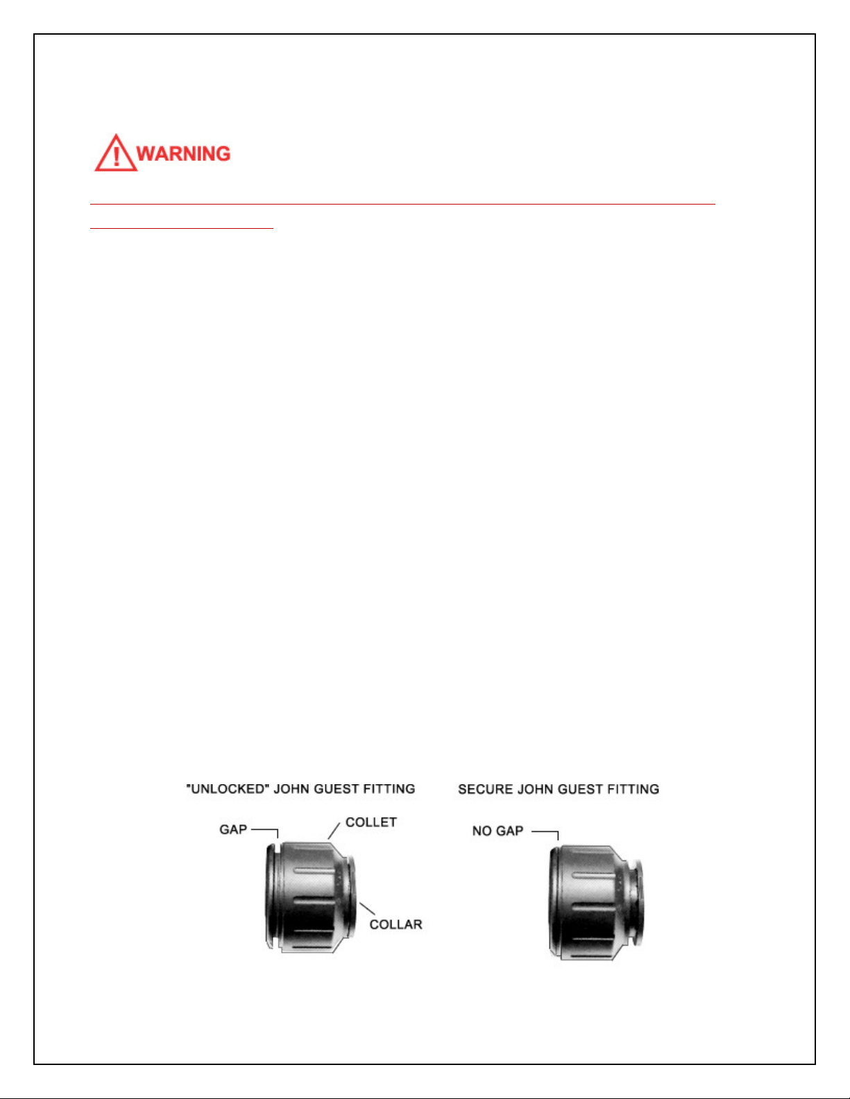
John Guest® Quick-Connect Style Fittings
Several steps in the installation use a special type of quick connect fitting made by
John Guest®. To connect a John Guest® fitting, unlock the fitting by turning the collet
counter-clockwise until the fitting loosens. A small gap will open between the collet
and the back of the fitting. Push the tube firmly into the fitting as far as it will go. Turn
the collet clockwise until tight to secure the fitting. Pull out on the tube to ensure a
good connection has been made. The pipe can be removed from the fitting by
loosening the collet again and depressing the collar evenly while pulling outward on
the tube.
7
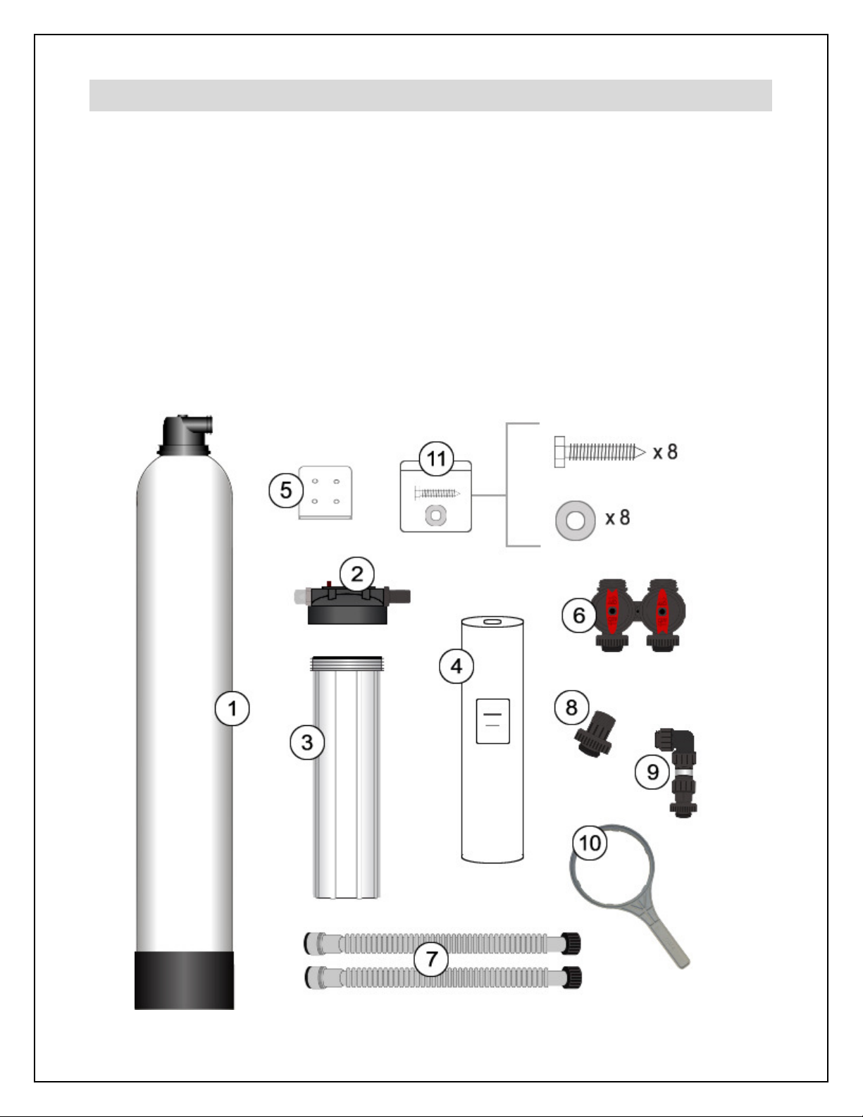
Step 1. – Pre-Installation Inspection
Inspect all of the components that you received with your unit. You should have received the
following:
1. ecoPlus™ Media Tank and Valve Head
2. artridge Filter Housing ap
3. artridge Filter Housing Sump
4. Sediment Pre-Filter (shipped inside #3)
5. Mounting Bracket
6. Bypass Assembly
7. Flexible Stainless Steel onnectors
8. Outlet Assembly
9. Inlet Assembly
10. Spanner Wrench
11. Small Parts Bag
(8 Lag Bolts and 8 Washers)

8
Step 2. – Selecting an Installation Location
While exterior installation in warm climate areas is possible, we strongly recommend interior
installation only. The system cannot be allowed to freeze or severe system damage could
occur. The system should not be exposed to rain and it should not be installed in direct
sunlight, as long-term exposure to UV light could damage components of the system.
Select a location for installation of your water filter that is within close proximity to the main
incoming water line of the home. The location should have a firm, level surface with enough
space for the unit itself and sufficient space surrounding the unit to facilitate maintenance.
The approximate minimum installation space required for
this model is:
28.5” Wide x 53” High x 20.5” Deep
In most cases, the system should be installed after the
branch line(s) to exterior irrigation, unless you want your
exterior faucets to deliver treated water. Depending on
the configuration of your plumbing system, this is not
always possible. ecoPLUS™ should be installed after
your pressure tank and booster pump, if applicable, and
before your hot water heater.
IF YOU HAVE OTHER WATER TREATMENT EQUIPMENT
YOU SHOULD DISCUSS THE ORDER OF YOUR TREATMENT EQUIPMENT WITH YOUR
DEALER PRIOR TO INSTALLATION.
WHILE WATER LEAKS ARE VERY RARE AND UNEXPECTED YOUR WATER FILTER
SYSTEM SHOULD BE LOCATED NEXT TO A FLOOR DRAIN OR PROTECTED BY A WATER
LEAK DETECTION SYSTEM WITH AUTOMATIC SHUT-OFF VALVE TO PREVENT WATER
DAMAGE TO YOUR PROPERTY IN THE UNLIKELY EVENT OF A WATER LEAK.
RECOMMENDED WATER LEAK DETECTION SYSTEMS ARE AVAILABLE AT WWW.A-LEAK-
DETECTOR.COM.
53”
28.5
”
9
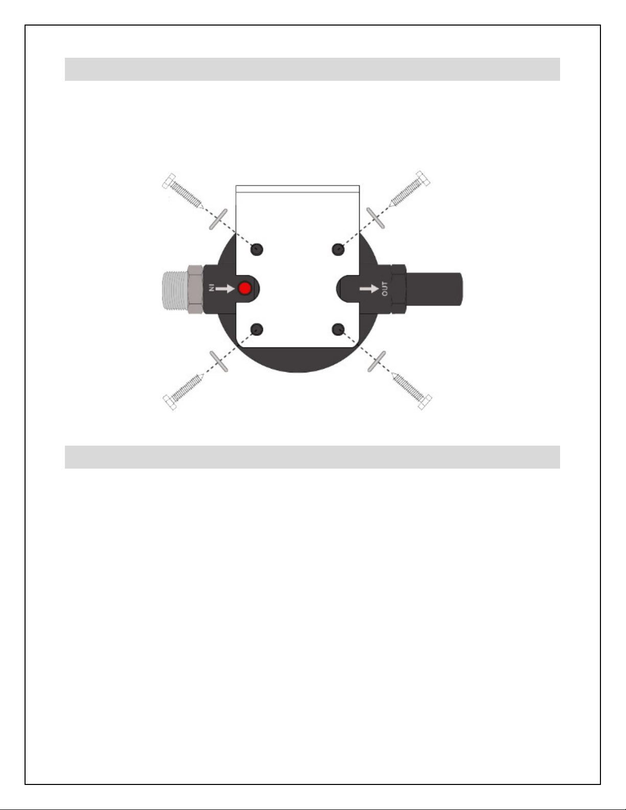
Step 3. – Attach Mounting Bracket to Housing Cap
Using four (4) of the lag bolts and washers from the small parts bag, attach the mounting
bracket to the cartridge filter housing cap as shown in the diagram below. The inlet of the
housing should be on the left.
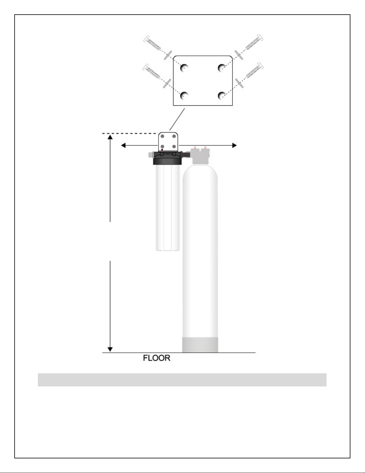
Step 4. – Attach Housing Cap to Wall
Attach the cartridge filter housing cap and mounting bracket to your wall using the
remaining four (4) lag bolts and washers as shown below. The top of the mounting
bracket should be mounted EXACTLY 52 3/4 (52.75) inches off the floor. Use a carpenter’s
level to ensure that the bracket is mounted level to the floor. You will need to ensure that
there is adequate space on either side of the bracket to accommodate the system. You will
need approximately 9-12 inches on the left and 15-18 inches on the right.
If mounting to drywall, we recommend that you use suitable wall anchors or that you mount
a small piece of 3/4 inch plywood to the wall first, ensuring that it is securely screwed into
the wall studs. When the cartridge filter housing is full of water, it is heavy, so it is important
to ensure that the mounting will be strong enough to support the weight.
10
Step 5. – Install Cartridge Filter and Attach Sump
Remove the protective plastic wrap from the sediment pre-filter and place it in the cartridge
filter housing sump. At the bottom of the sump, there is a raised portion in the middle
(standpipe) that will help center the filter in the housing. The standpipe will fit inside the hole
52 3/4 inches
from floor to
top of bracket
9 inches
clearance to
left of bracket
15 inches
clearance to
left of bracket
Table of contents
Other HomePluss Water Filtration System manuals


Popular Water Filtration System manuals by other brands

Atlantic Ultraviolet
Atlantic Ultraviolet Mighty Pure MP16A owner's manual

SunSun
SunSun CBG-500 Operation manual

Hayward
Hayward XStream Filtration Series owner's manual

Contech
Contech DownSpout StormFilter Operation and maintenance

Teka
Teka Airfilter MINI operating instructions

Wisy
Wisy LineAir 100 Installation and operating instructions

Schaffner
Schaffner Ecosine FN3446 Series User and installation manual

Pentair
Pentair FLECK 4600 SXT Installer manual

H2O International
H2O International H20-500 product manual

Renkforce
Renkforce 2306241 operating instructions

Neo-Pure
Neo-Pure TL3-A502 manual

STA-RITE
STA-RITE VERTICAL GRID DE FILTERS S7D75 owner's manual


