fault LED Indicator
Remote control-LCD
Power LED
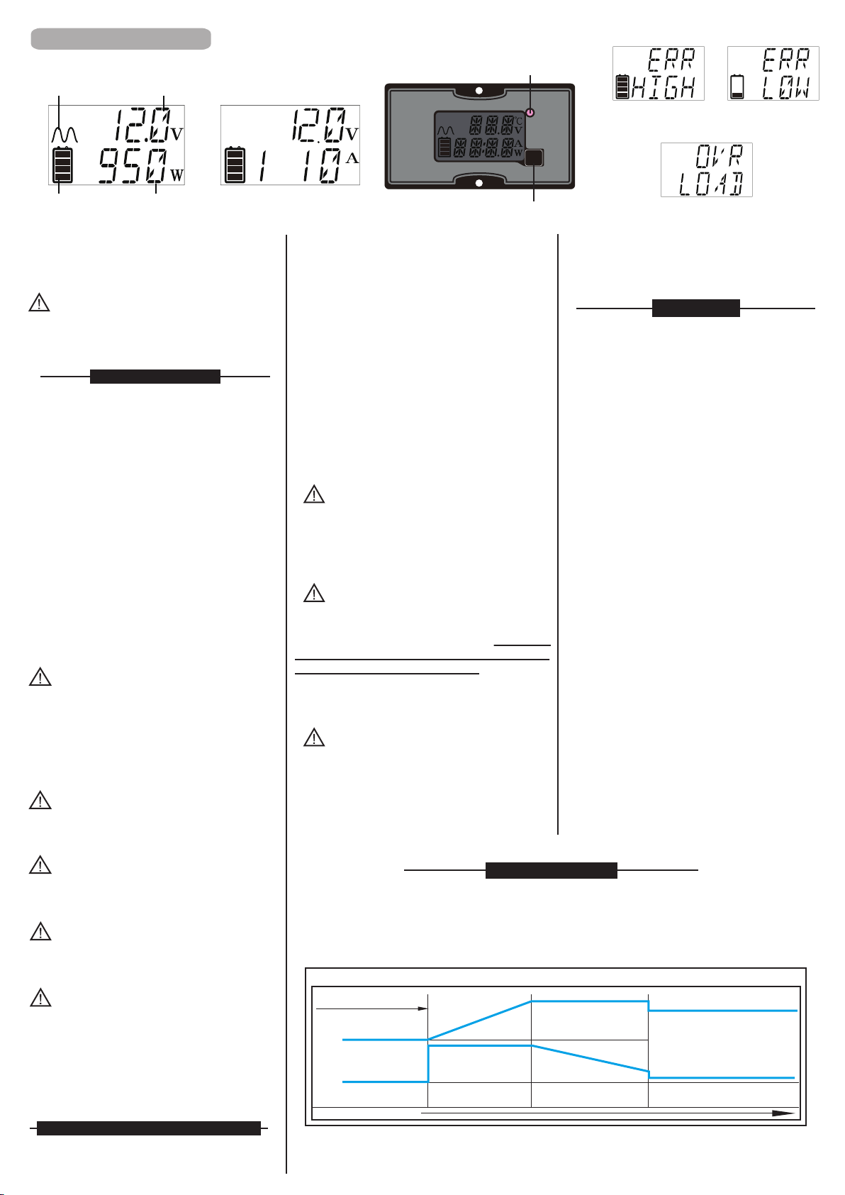
Waveform
Battery volt
Load watts
Battery capacity
High battery
volt protection. Low battery
volt protection.
Over temperature / Overload
If you would like to quick hook-up the power inverter/
5.
Connect the cable from the positive terminal
of inverter/charger tothe positive terminal of
the power source. Make secure connection.
WARNING!!
You may observe a spark when you make this
connection since current may flow to charge
capacitors in the power inverter.
Do not make this connection in the presence
of flammable fumes, explosions or fire may
result.
If you would like to quick hook-up the power inverter/
charger and check its performance before going
ahead with your installation, please follow these
guideline.
1.
Unpack and inspect the inverter/charger, check
to see that the power switch in the OFF position.
2.
Connect the cables to the power input terminals
on the rear panel of inverter/charger. The red terminal
is positive (+) and black terminal is negative (-).
Connect the cables into the terminals and tighten
the wing nut
to the wires securely.
3.
Connect the cable from the negative terminal
of the inverter/charger tothe negative terminal
of the power source. Make a secure connection.
CAUTION!!
Loosely tightened connectors result in
excessive drop and may cause overheated
wires and melted insulation.
4.
Before proceed further, carefully check if
the terminals connect correctly.
CAUTION!!
Reverse polarity connection will blow a fuse
in inverter/charger and may permanently
damage the inverter/charger. Damage
caused by reverse polarity connection is
not
covered by our warranty.
charger status display
For lead-acid and lead-calcium batteries only.
Stage1: Bulk Charge Max 14.5±0.5V, 10A.
Stage2: Absorption Charge 14.5±0.5V, 10~1A.
Stage3: Float Charge 13.6±0.5V, min. 0.5A.
Battery Charger
Charging started
Multistage Battery Charger
DC Voltage
DC Current
Time
Bulk stage
Constant current
at maximum
charge rate
Absorption stage
Constant voltage
at Absorption
voltage setting
Float stage
Constant voltage
at the Float
voltage setting
Load current on demand
Charger LED
Indicator Red Red Orange
your Amp-hour consumption between charging
cycles and use a battery bank with twice that
capacity.
To calculate Amp-hour consumption first look
at the rating plate on your AC appliance or tools.
Each appliance or tool will be rated in either
AC Amps or AC watts or AC VA (Volts-Amps)
apparent power.
Use one of the following formulas to calculate
the DC Amp-hour draw for a 12 Volt system:
(AC Amps x 10) x 1.1 x hours of operation
= DC Amp-hours
(AC watts/12) x 1.1 x hours of operation
= DC Amp-hours
(AC VA/12) x 1.1 x hours of operation
= DC Amp-hours
6. Set power inverter switch to the ON position
and turn the test load on, the inverter should
supply power to the load.
To achieve 50% cycling you should calculate
Batteries
Calculate the above for every AC appliance or
tool you intend to use on your inverter. This
will give you the total number of Amp-hours
used between recharges. Size your battery bank
using this number as a guideline.A good rule
to follow is to size the battery bank about 2times
larger than your total Amp-hour load requirement.
Plan on recharging when 50% discharged.
Many electric motors have monentary starting
requirements well above their operational rating.
Start up watts are listed where appropriate.
lndividual styles and brands of appliances may
vary.
In all formulas, 1.1 is the factor for inverter/charger
efficiency.
Quick hook - up and testing
compartment, overheating may result.
CAUTION!!
Risk of electrical shock. Both AC & DC voltage
sources are existed inside this equipment.
Each circuit must be individually installed.
CAUTION!!
Risk of electrical shock. Do not remove
cover, no user serviceable parts inside.
Refer servicing to qualified service personnel.
APPLICATION INFORMATION:
Provided with integral electronic protection
against AC & DC overloads.
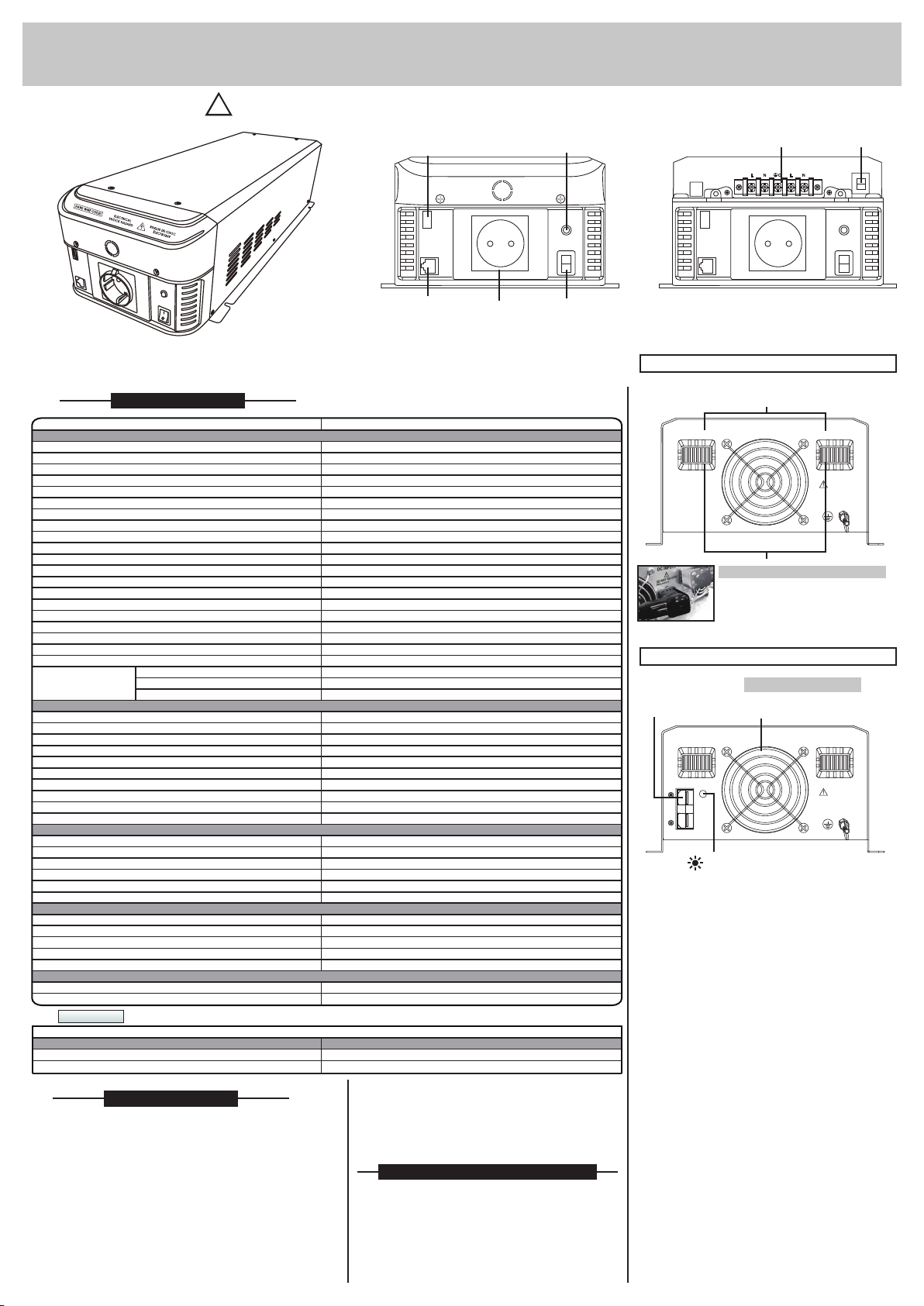
Installation
1. Where to install
The inverter/charger should be installed in a
location that meets the following requirements:
a. Dry - Do not allow water to drip or splash
on the inverter/charger.
d. Safe - Do not install the inverter/charger
in the same compartment as batteries or
in any compartment capable of storing
flammable liquids such as gasoline.
CAUTION!!
This equipment is not ignition protected and
employs components that tend to produce
arcs or sparks. To reduce the risk of fire or
explosions, do not install in compartments
containning batteries or flammable materials
or areas in which ignition protected equipment
is required.
CAUTION!!
To reduce the risk of electric shock and
prevent premature failure due to corrosion,
do not mount where exposed to rain or spray.
CAUTION!!
To prevent fire, do not obstruct ventilation
openings. Do not mount in a zero clearance
c.
Ventilated - Allow at least 3 inch (15cm)
of clearance around the inverter for airflow.
Ensure the ventilation openings on the rear
and bottom of the unit are not obstructed.
b.
Cool - Ambient air temperature should
be between -15°C ~ 45°C, the cooler
environment is better.
Reverse polarity connection will blow internal
fuse and may damage inverter/charger
permanently.
WARNING!!
Operation of the inverter/charger without a
proper ground connection may result in an
electrical safety hazard.