Honeybee AirFlex SDX User manual
200 Series & SDX
Quick Start Guide
2019
®
This guide is a supplement to the operators manual, do
not aempt to operate your equipment without rst
reading and understanding the full operator manual.
When you exit the combine, shut o the combine,
engage the parking brake, and wait for all moving parts
to come to a complete stop before approaching the
header.
If working on a raised header, ensure the feeder house
cylinder locks are in place.
Do not wear loose clothing or jewelry around moving
parts.
Avoid high pressure hydraulic spray. Seek medical
aenon immediately if it punctures your skin.
Ensure all equipment is secured against sudden drops.
Read and understand all safety instrucons in the
operator manual before proceeding.
Revision 1.2 P/N: 95111

Document Revision History
Revision Author Date Description
1.0 AD 05/26/2019 Document Created
1.1, 1.2 AD 05/29/2019 Spelling corrected, removed mention of upper stop bolt on
auger drum.

Page 3 Revision 1.2 P/N: 95111
Honey Bee Manufacturing Ltd.
AirFLEX 200 Series & SDX Header - Quick Start Guide
Header Preparaon
Raise front reel bats to
operaonal posion and
secure to the control arms
using the preinstalled nut and
bolt.
Remove and store the e-down brackets located
on the transport mounng bracket and strut on
the le side of the header.
Reinstall the ngs which secure the paddle pivot
pin.
Remove the wire holding the reel arms
and reel in place. Inspect thoroughly as
the wires can be in mulple locaons.
Ensure dividers are
securely installed
Secure divider with bolt.
Secure divider with handle.
Page 4 Revision 1.2 P/N: 95111
Honey Bee Manufacturing Ltd.
AirFLEX 200 Series & SDX Header - Quick Start Guide
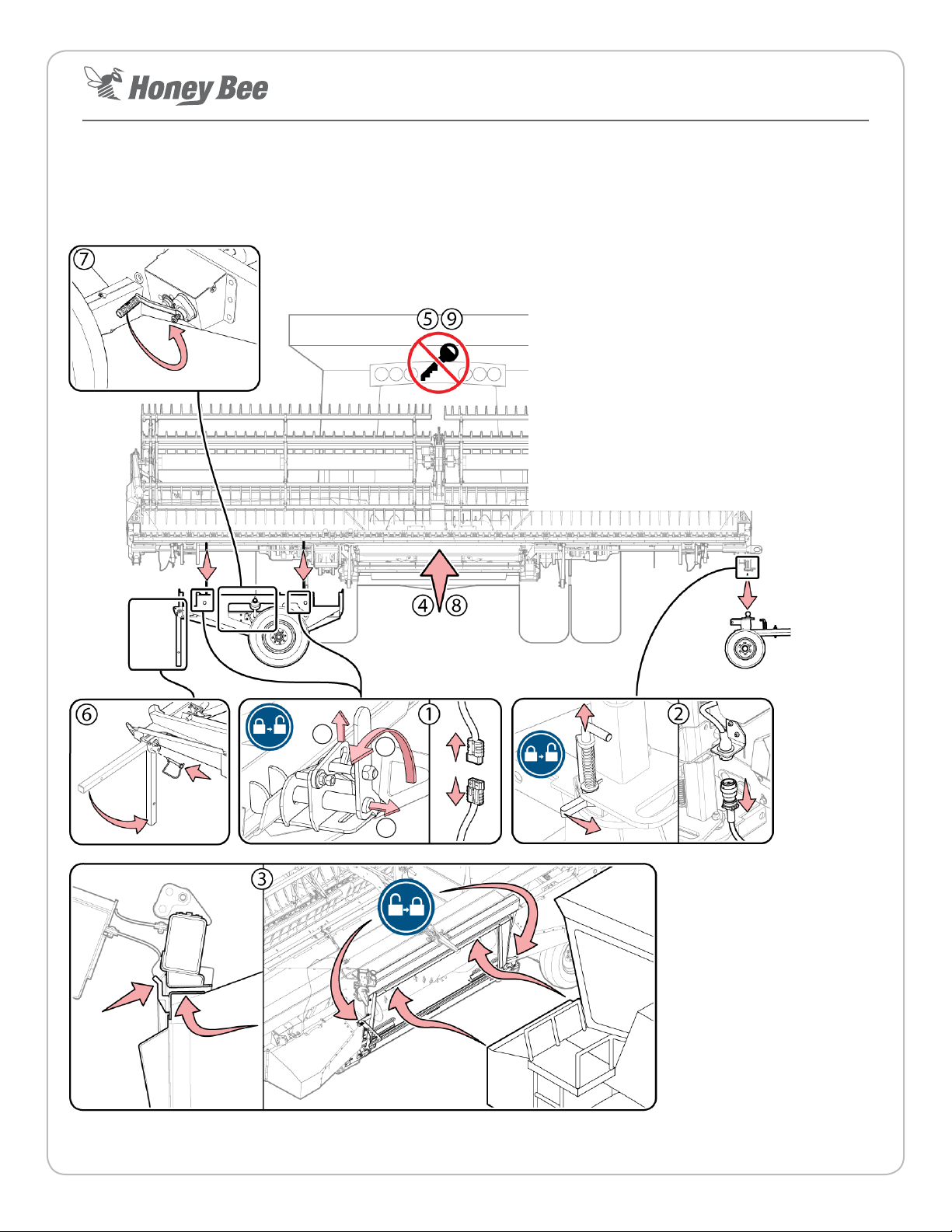
Mounng the Header 1 Release the two transport cart locks and disconnect
the cart’s electrical harness.
2 Release the draw bar lock and disconnect it’s
electrical harness.
3 Slowly drive the combine forward unl the feeder
house is inserted into the feeder house opening.
Ensure it is properly aligned
4 Slowly li the header 1-2 feet above its current
posion to release the transport cart & drawbar.
5 Shut down the combine, engage the parking brake
and engage the feeder house locks.
6 Lower the transport cart support bar and secure pin.
7 Lower the trasport cart with the hand crank and
unhook the straps from the header.
8 Raise the header and back away from the cart,
lower the header back down to a working height.
9 Shut down the combine, engage the parking brake
and engage the feeder house locks.
AB
C
Page 5 Revision 1.2 P/N: 95111
Honey Bee Manufacturing Ltd.
AirFLEX 200 Series & SDX Header - Quick Start Guide
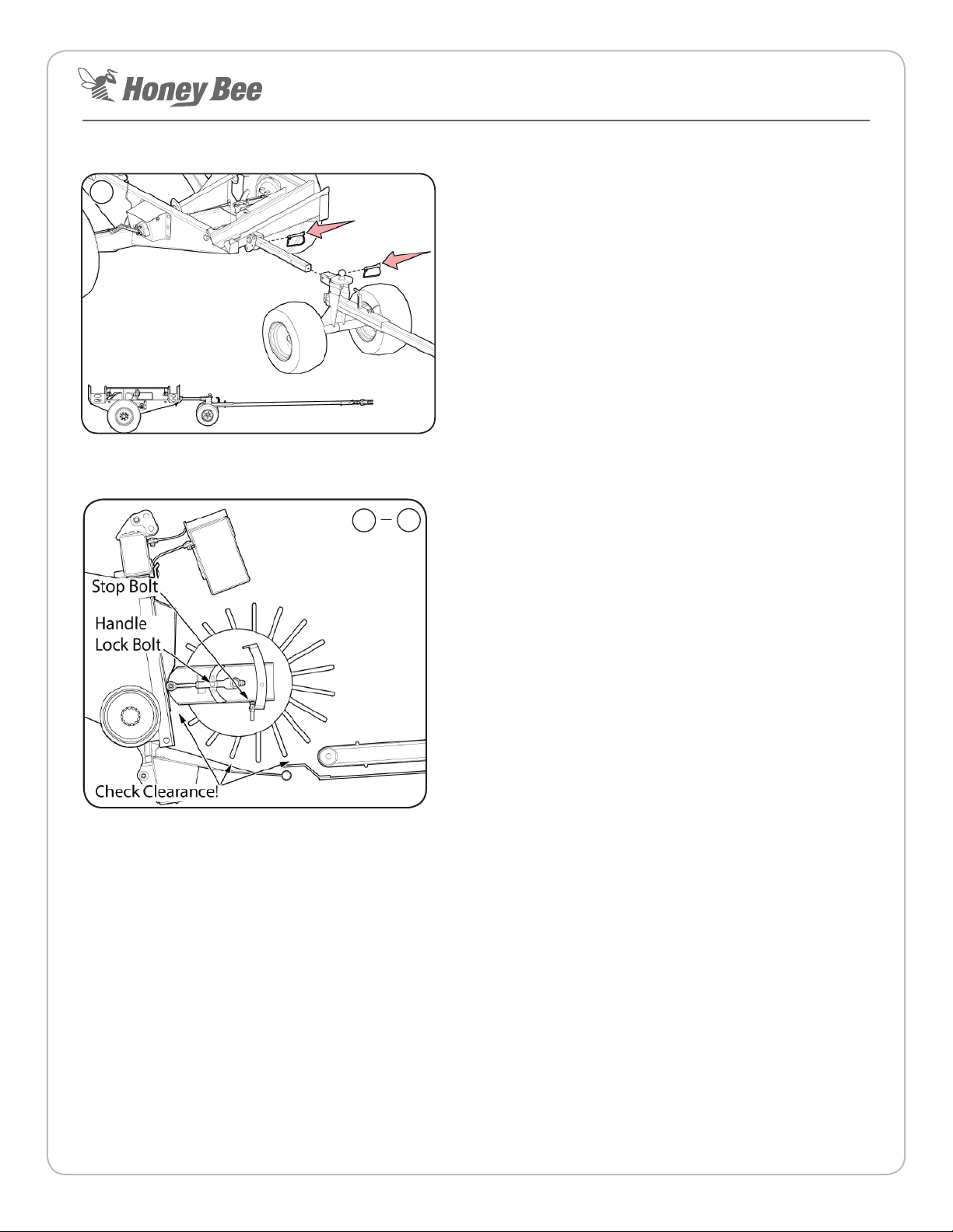
Secure the transport cart and draw bar cart together, secure
with pins as illustrated and place in a storage locaon.
Evenly adjust the le and right eye bolts on the feed auger drum
so it is moved to within 1/2”(1.3 cm) of the combine feeder
house protrusions.
Set the feed auger drum lower stop bolts to prevent the drum
from contacng the rest of the header.
Rotate the auger drum by hand to ensure it will not contact the
protrusions, ghten the lock nuts on the eye bolts.
Set Feed Auger nger ming so the feed auger ngers maintain
adequate clearance from the components surrounding the feed
auger drum.
Check All Clearances around the feed auger drum and adjust
accordingly.
10
Finish Mounng
11 15

Page 6 Revision 1.2 P/N: 95111
Honey Bee Manufacturing Ltd.
AirFLEX 200 Series & SDX Header - Quick Start Guide
Make Connecons
1 Turn o the combine’s master baery switch.
2 Make the hydraulic and electrical
connecons at the mulcoupler
located on the le side of the
feeder house. Connect both
drive shas to the combine.
3 Starng at the front of the combine, route
the automax harness under the combine
cab and inside. Connect to the automax
display. Route the remianing poron of the
harness to the combine’s baery. Connect
the harness to the power system aer the
power switch to ensure the Automax does
not drain the baery when the combine is
turned o.
Ensure enough slack is le in the electrical
harness at the feeder house pivot for it to go
through its full range of moon.
Page 7 Revision 1.2 P/N: 95111
Honey Bee Manufacturing Ltd.
AirFLEX 200 Series & SDX Header - Quick Start Guide
Header Setup Overview
1. Ensure each sensor ‘ag’ contacts its roller at the ‘heel’
of each strut at the rear of the header. The Flag should
contact the center of the roller. The two outermost sensor
tabs should be rmly in contact with their rollers while the
remaining tabs should only lightly touch their rollers. This
ensures the system reacts to input from the outer ends of
the header rst.
Roller
Flag
2. Verify the header height sensor voltages on the
AutomaxLite display:
RIGID mode header height control only pertains to the 200
series header. RIGID header height control sensors are not
installed on the SDX and therefore informaon about RIGID
sensors in this quick start guide can be ignored for the SDX
plaorm.
• In FLEX Mode: With the header air system pressurized
to approximately 30 psi, the sensor voltages should
range between 1.5 and 3.5 volts through the cuer
bar’s full range of moon.
• RIGID Center Subframe Sensing Mode (default from
factory): With the header air system pressurized to
approximately 90 psi, the sensor voltages should
range between 1.5 and 3.4 volts through the subframe
sensor’s full range of moon.
• RIGID Divider Mode (must be acvated by swapping
sensor wires and unlocking dividers as described
in operator manual): With the header air system
pressurized to approximately 100 psi, the sensor
voltages should range between 1.5 and 3.5 volts
through the divider’s full range of moon.
Note: Refer to operator manual for detailed instrucons.
IMPORTANT: Don’t make assumpons, don’t skip steps, x all
errors that occur before connuing.
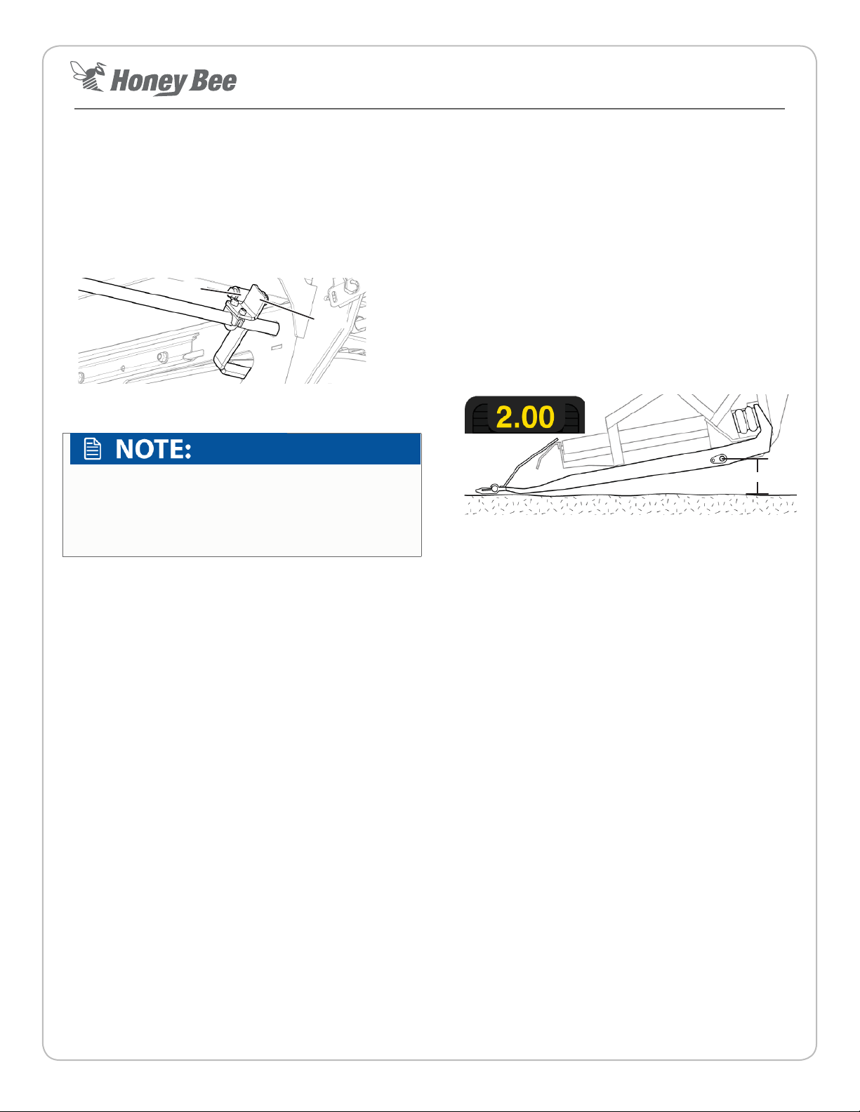
Set combine feeder house angle.
The Combine Feeder House must be lted at a specic angle
for opmal header operaon. To set proper operaon angle.
1. Park the combine and header on a rm level surface.
2. Set the header to FLEX mode and lower the air pressure
unl 30psi is reached.
3. Fully retract the hydraulic lt cylinder.
4. Lower the table unl the cuer bar is fully pushed up.
5. Slowly raise the header unl 2.00 volts (8 bars) show on the
sensor bar graph on the Automax Lite display
6. Measure down to the ground from the pivot point of the
outer-most paddle. There should be an 6-7” (15.4 - 17.8 cm)
space when at the opmal feeder house angle.
6-7” (15.2-17.8 cm)
• If the paddle ‘heel’ is more than 6-7” (15.2 - 17.8 cm)
above the ground, the feeder house is lted too far
forward and the cuer bar guards will dig into the
ground.
• If the paddle ‘heel’ is less than 6-7” (15.4 - 17.8 cm)
above the ground, the feeder house is not lted
forward enough and the rear of the paddle will drag on
the ground. 6-7” (15.2-17.8 cm)
7. Adjust the feeder house angle as necessary and re-test the
angle as outlined in the previous steps. Tilt can be adjusted
to suit ground condions and habits of the operator.

Page 8 Revision 1.2 P/N: 95111
Honey Bee Manufacturing Ltd.
AirFLEX 200 Series & SDX Header - Quick Start Guide
Combine Calibraon
1. The combine must be run at maximum RPM (harvest
speed) and the hydraulic oil must be up to operang
temperatures during calibraon.
2. Check the oil level to ensure there is no air in the system
(normally heard as a whining noise).
3. Set the AIRFLEX via the AutoMax Lite monitor to RIGID
mode if cung o the ground or FLEX mode if cung on
the ground.
4. Set combine hydraulic header raise rate so it takes 6
seconds to li the header from the lowest posion to the
highest posion.
5. Set combine hydraulic header drop rate so it takes 7
seconds to lower the header from the highest posion to
the lowest posion.
6. Refer the 200 Series/SDX operator’s manual for specic
instrucons on calibrang in each mode. Calibrate the
combine’s header height sengs as described in the
combine’s operator manual.
7. Slowly increase header height sensivity via combine
controls unl the header starts hunng up and down.
Decrease sensivity by 10-20% unl the header stops
hunng. Set the lt sensivity to half the height sensivity
minus 10%, so if the header height sensivity is set to 200,
the lt sensivity should be set to approximately 90 (200/2
= 100, 100 - 10% = 90).
8. When the combine calibraon is done, lower and run
the header and combine rotor so automac header
height is enabled. Record a set-point for header height
on the combine (i.e. 4” (10 cm)). Raise the table all the
way up and laterally lt it all the way to the le or right.
Press the return to set point buon on the combine.
The header should lower back to the set point AND level
out automacally. If this fails, it may indicate a combine
soware problem.
The combine specic sengs listed on the following
pages are recommendaons only. Opmal sengs will
vary by equipment conguraon and condions. It is
the equipment operator’s responsibility to ensure they
operate their equipment in a safe, ecient manner.
Reel Setup
Set the pitch of the reel ngers via the adjuster at the end of
the reel. The middle posion is a good place to start. If crop is
wrapping around the reel, set a less aggressive nger pitch.
Ensure the reel is level and that the reel ngers maintain
a minimum distance of 1-1/2” (3.8cm) from the cuer
bar. Adjust the reel height adjustment bolts located on the
underside of the reel arms if necessary.
Calibraon Troubleshoong:
Check that the combine is receiving the correct sensor voltages
from the header sensors.
Verify the correct combine sengs have been entered.
Inspect crop dividers, metal should contact metal if they are
lied and dropped. If the springs are too ght, the dividers
will ride up.
If header is not reacng quick enough, sensivies may
need to be increased. If header is hopping or jumping then
sensivies may need to be decreased.
Page 9 Revision 1.2 P/N: 95111
Honey Bee Manufacturing Ltd.
AirFLEX 200 Series & SDX Header - Quick Start Guide
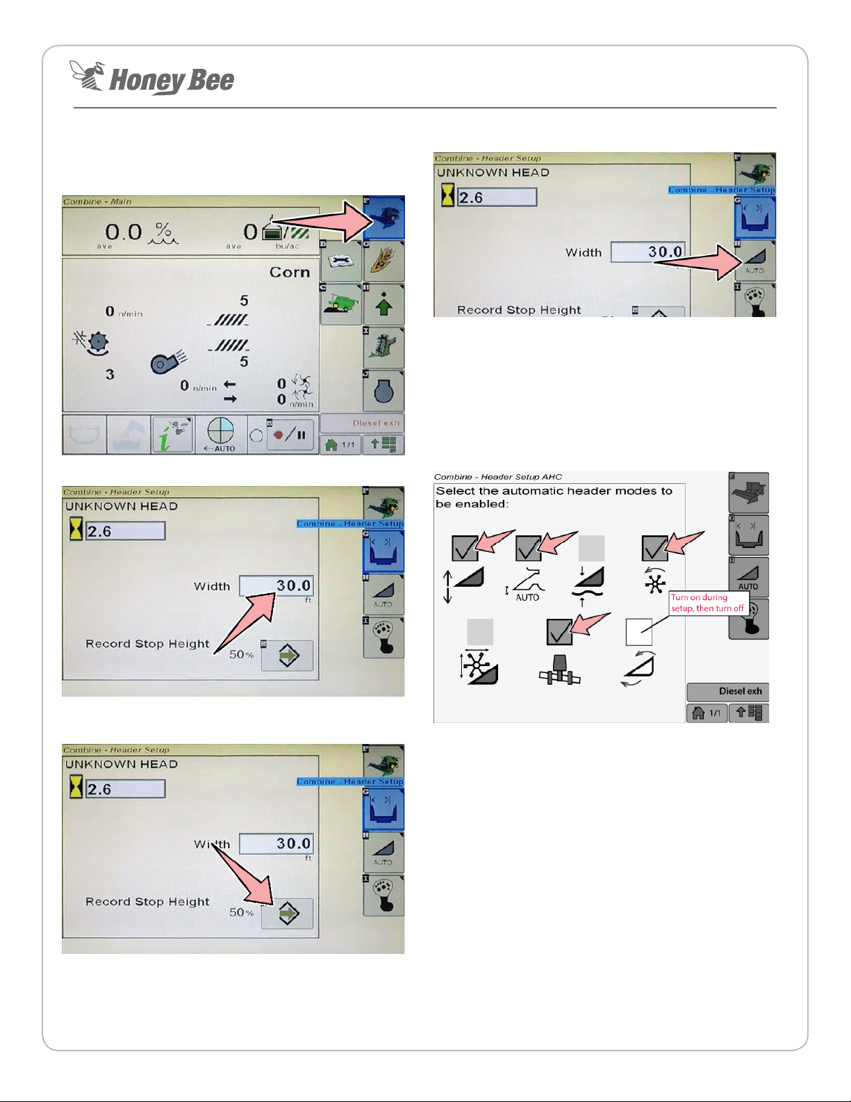
John Deere S550 and S600 Series Combines
1. Enter the combine’s header setup screen by selecng the
header icon.
2. Set the header width.
3. Raise the header to 60% of it’s maximum height and press
the enter buon to save the value.
4. Select the Auto Header screen via the AUTO buon.
5. Ensure the following boxes are checked:
• Header Height Control
• Auto HHC
• Auto reel speed
• Auto lt
• During setup, faceplate angle must be set.
Page 10 Revision 1.2 P/N: 95111
Honey Bee Manufacturing Ltd.
AirFLEX 200 Series & SDX Header - Quick Start Guide
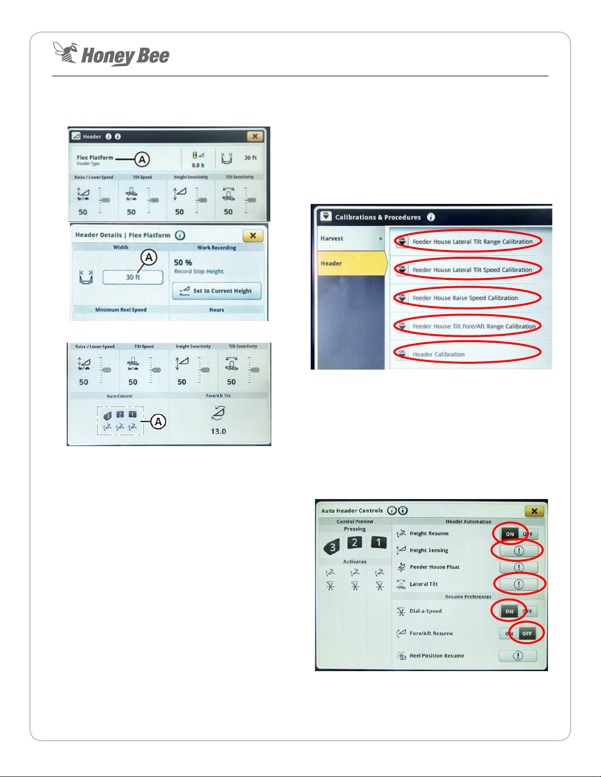
John Deere S700 Series Combines
1. Set the header width via the header screen
2. Select the Auto Contour icon (A) to get to setup screen.
3. The following calibraons must be peformed starng at
the top of the list and working your way down:
• Feeder House Lateral Tilt Range Calibraon
• Feeder House Lateral Tilt Speed Calibraon
• Feeder House Raise Speed Calibraon
• Feeder House Tilt Fore/A Range Calibraon
• Header Calibraon (Must be performed last)
4. Once all the calibraons are done (including the header
calibraon) then the Header Automaon sengs can be
set. Then set the following sengs on the Auto Header
Controls screen:
• Height Resume: On
• Height Sensing: Acvate
• Lateral Tilt: Acvate
• Dial-a-Speed: On
• Fore/A Resume: O
This manual suits for next models
1
Table of contents
Other Honeybee Farm Equipment manuals


Popular Farm Equipment manuals by other brands

Schaffert
Schaffert Rebounder Mounting instructions

Stocks AG
Stocks AG Fan Jet Pro Plus 65 Original Operating Manual and parts list

Cumberland
Cumberland Integra Feed-Link Installation and operation manual

BROWN
BROWN BDHP-1250 Owner's/operator's manual

Molon
Molon BCS operating instructions

Vaderstad
Vaderstad Rapid Series instructions


