Honeywell Home Inland Breeze 50510 User manual

1
User Guide
Inland Breeze Ceiling Fan
Model #50510, 50511
INDEX
Package Contents .............................................................................................................2
Hardware Contents ............................................................................................................2
Safety Information.............................................................................................................3
Care and Maintenance ........................................................................................................3
Preparation....................................................................................................................4
Initial Installation..............................................................................................................4
Standard or Angle Mount Instructions .........................................................................................5
Closemount Instructions ......................................................................................................6
Final Installation ..............................................................................................................6
Installation Without Light Kit ..................................................................................................8
Operating Instructions ........................................................................................................9
Troubleshooting ...............................................................................................................9
Warranty .................................................................................................................... 10
Replacement Parts List ...................................................................................................... 10
Home

2
PACKAGE CONTENTS
HARDWARE CONTENTS
Mounting Bracket Screw (x 4)
Switch Housing Screw (x 3)
Bulb (x 2)
Mounting Bracket
Canopy
Canopy Cover
Downrod
Downrod Clip
Downrod Pin
Blade Arm (x 5)
Blade (x 5)
Yoke Cover
Yoke
Finial
Closemount
Screw (x 3)
Motor Assembly
Switch Housing
Switch
Housing
Cap
Light Kit
Glass Bowl
Blade Balancing Kit
Plug Button
Blade Washer (x 15)
Blade Screw (x 15)
Wire Connector (x 3) Pull Chain Extension (x 2)

3
SAFETY INFORMATION
CARE AND MAINTENANCE
Please read and understand this entire manual before attempting to assemble, operate or install the product.
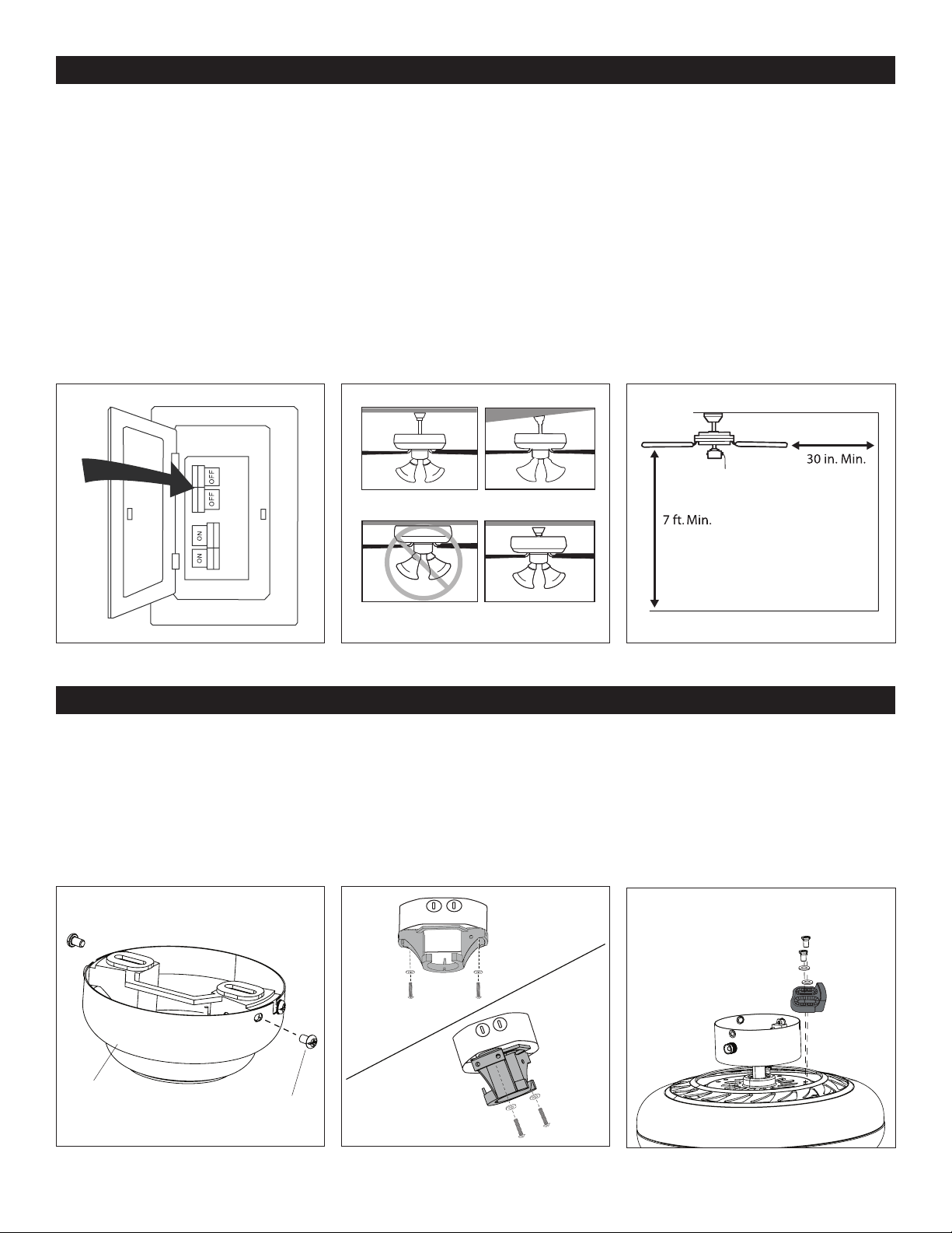
• Before you begin installing the fan, disconnect the power by removing fuses or turning off the circuit breakers.
• Make sure all electrical connections comply with local codes, ordinances, the National Electrical Code and ANSI/NFPA
70-199. Hire an electrician or consult a do-it-yourself handbook if you are unfamiliar with installing electrical wiring.
• Make sure the installation site you choose allows a minimum of 7 feet from the blades to the oor and at least 30 inches from
the tip of the blades to any obstruction.
• The weight of the fan is 23.01 pounds.
DANGER: When using an existing outlet box, make sure it is securely attached to the building structure and can support
the full weight of the fan. Failure to this can result in serious injury or death. The stability of the outlet box is essential in
minimizing wobble and noise in the fan after installation is complete.
WARNING: To avoid personal injury, the use of gloves may be necessary while handling fan parts with sharp edges.
WARNING: Using a full-range dimmer switch to control fan speed will cause a humming sound from the fan. To reduce the
risk of re or electric shock, do NOT use a full-range dimmer switch to control fan speed.
WARNING: To reduce the risk of fire, electric shock or personal injury, mount the fan to an outlet box marked
“ACCEPTABLE FOR FAN SUPPORT” and use the mounting screws provided with the outlet box. Most outlet boxes commonly
used for the support of lighting fixtures are not acceptable for fan support and may need to be replaced. Consult a qualified
electrician if in doubt. Secure the outlet box directly to the building structure. The outlet box and its support must be able to
support the moving weight of the fan (at least 35 lbs.).
WARNING: To reduce the risk of fire, electric shock or personal injury, wire connectors provided with this fan are designed to
accept only one 12-gauge house wire and two lead wires from the fan. If your house wire is larger than 12-gauge and/or there is
more than one house wire to connect to the two fan lead wires, consult an electrician for the proper size wire connectors to use.
WARNING: To reduce the risk of fire, electric shock or personal injury, do not bend the blade arms when installing them,
balancing the blades or cleaning the fan. Do not insert objects between the rotating fan blades.
WARNING: To reduce the risk of personal injury, use only parts provided with this fan. The use of parts other than those
provided with this fan will void the warranty.
CAUTION: Be sure the outlet box is properly grounded or a ground (green or bare) wire is present.
CAUTION: Carefully check all screws, bolts, and nuts on the fan assembly ensure they are secured.
This equipment has been tested and found to comply with the limits for a Class B digital device, pursuant to Part 15 of the FCC
Rules. These limits are designed to provide reasonable protection against harmful interference in a residential installation.
This equipment generates, uses and can radiate radio frequency energy and, if not installed and used in accordance with the
instructions, may cause harmful interference to radio communications. However, there is no guarantee that interference will not
occur in a particular installation. If this equipment does cause harmful interference to radio or television reception, which can
be determined by turning the equipment off and on, the user is encouraged to try to correct the interference by one or more of
the following measures:
--Reorient or relocate the receiving antenna.
--Increase the separation between the equipment and receiver
--Connect the equipment into and outlet on a circuit different from that to which the receiver is connected.
--Consult the dealer or an experienced radio/TV technician for help.
Please note changes or modifications not expressly approved by the party responsible for compliance could void the user’s
authority to operate the equipment.
At least twice each year, lower the canopy to check the downrod assembly and tighten all screws on the fan. Clean the motor
housing and blades with a soft brush or lint-free cloth to avoid scratching the finish.
Important: Shut off the main power supply before you begin any maintenance task. Do NOT use water or a damp cloth to clean
the fan.

4
INITIAL INSTALLATION
PREPARATION
Before beginning the assembly of this product, ensure all parts are present. Compare all parts with the package contents list
and hardware contents list. If any part is missing or damaged, do not attempt to assemble the product.
Estimated assembly time: 2 hours
Tools required (not included): Electrical tape, Phillips Screwdriver, Safety Glasses, Step Ladder, and Wire Strippers.
1. Turn off power to the fan at the breaker box and the wall switch (Figure 1.1). DANGER: Failure to disconnect the power supply
prior to installation may result in serious injury or death.
2. Choose one of the following mounting options (Figure 1.2) :
Standard Mount - best suited for ceilings 8 feet or higher. For very high ceilings, use a longer downrod (not included).
Angle Mount - best suited for angled or vaulted ceilings. A longer downrod is sometimes necessary to ensure proper blade
clearance. Ensure the ceiling angle is not steeper than 16 degrees.
Flushmount Installation - not available for this model.
Closemount Installation - best suited for ceilings 8 feet or lower.
3. Choose a suitable location - Ensure the blades will be at least 30 inches from any obstructions. Also check the downrod
length to ensure the blades will be at least 7 feet above the oor (Figure 1.3).
D
Figure 1.1
Figure 2.1
Figure 1.2
Standard and
Closemount
Angle Mount
Mounting
Bracket Screw
Canopy
Figure 2.2
Figure 1.3
Figure 2.3
Standard Mount
Flushmount
Angle Mount
Closemount
1. Loosen all four mounting bracket screws and completely remove the two screws from the round holes in the canopy. Then
remove mounting bracket from the canopy and save them for later (Figure 2.1).
2. Install the mounting bracket to the outlet box (sold separately) using the screws and washers provided with the outlet box
(Figure 2.2).
3. Remove motor screws, motor blocks and washers from underside of the motor assembly. Discard the motor blocks and
washers but keep the motor screws for blade arm attachment (Figure 2.3).
For CLOSEMOUNT INSTRUCTIONS, skip to page 6.
Motor Screw
Motor Block
Washer

5
STANDARD OR ANGLE MOUNT INSTRUCTIONS
1. Feed the fan wires through the yoke cover, canopy and downrod (Figure 3.1).
2. Partially loosen the two set screws in the yoke at the top of the motor assembly to allow for installation of the downrod. Slide
the downrod into the yoke of the motor assembly. Align holes and reinstall the downrod pin and downrod clip and re-tighten
the set screws (Figure 3.2).
3. Depending on the length of downrod you use, you may want to cut the fan wires to simplify wiring. After pulling the wires all
the way through the downrod, measure 8 inches of wire. Cut off the excess wire using wire cutters (not included). Then strip
1/2 inch of insulation from the end of each wire strand (Figure 3.3).
4. Install the ball end of the downrod into the opening of the mounting bracket (Figure 3.4). WARNING: Failure to align the slot
in the ball with the tab on the mounting bracket may cause the fan to fall, which could result in injury or death.
Skip to FINAL INSTALLATION, page 6.
Figure 3.1
Figure 3.4
Downrod Clip
Set Screw Downrod
Downrod Pin
Downrod
Canopy
Yoke Cover
Figure 3.2 Figure 3.3
8 in.
Mounting
Bracket
Downrod Tab
Slot

6
FINAL INSTALLATION
Figure 4.2
Figure 5.2
Figure 4.1
Figure 5.1
Figure 4.3
Figure 5.3
WARNING: Do NOT wire the
fan motor to a variable-speed
(dimmer) wall control.
Mounting
Bracket Screw
Mounting
Bracket Screw
1. Use wire connnectors to connect household supply and fan wires according to the diagram (Figure 5.1) and the following
steps:
• Connect the green wire from the downrod and mounting bracket to the Bare/Green (ground) supply wire. Note: Closemount
installation does not use the downrod, so there will only be two Green wires to connect.
• Connect the White wire from the fan to the White (neutral) supply wire.
• Connect the Black and Blue wires from the fan to the Black (hot) supply wire.
Note: If there is a second hot supply wire in the outlet box, connect it to the blue (light power) fan wire for separate light and
fan control.
2. Align the canopy over the loosened mounting bracket screws. Place the L-slot of the canopy onto the mount bracket screws
and rotate counterclockwise (Figure 5.2).
3. Secure the canopy with the two previously removed mounting bracket screws. Tighten all the mounting bracket screws
securely (Figure 5.3).
Black (Hot)
Wire Connector
White (Neutral)
Bare/Green (Ground)
Black
Blue
White
Green
Canopy Cover
Closemount
Screw
Mounting
Bracket
Canopy
Canopy
Canopy
Hook
CLOSEMOUNT INSTRUCTIONS (optional)
1. Remove the canopy cover from the bottom of the canopy (Figura 4.1).
2. Remove the three Phillips-head closemount screws from the top of the motor assembly. Then align the canopy with the holes
in the top of the motor assembly. The larger holes in the canopy will encompass the remaining screws. Secure the canopy to
the top of the motor assembly with the previously removed closemount screws (Figura 4.2).
3. Raise the motor assembly and place the canopy on the hook of the mounting bracket to free hands during the wiring process
(Figura 4.3).

7
FINAL INSTALLATION
Figure 5.5
Figure 5.8
Figure 5.4
Figure 5.7
Figure 5.6
Figure 5.9
Blade Screw
Rubber Washer
Switch
Housing
Screws
Blade Washer
Blade Arm
Hex Nut
Glass Bowl
Light Kit
Switch Housing
Screw
Finial
Blade Arm
Motor Screw
Single-pin
Connector
Blade
Bulb
4. Partially insert the blade screws along with blade washer through blade and into the blade arm. Tighten each blade screw starting
with the one in the middle. Repeat this step for the remaining blades and blade arms (Figura 5.4).
5. Install the blade arm to the underside of the motor assembly using the ten previously removed motor screws (Figure 5.5). To
INSTALL THE FAN WITHOUT THE LIGHT KIT, skip to page 8.
6. Remove the three switch housing screws from the top edge of the light kit. Then, remove the finial, hex nut, rubber washer,
and glass bowl from the light kit (Figure 5.6).
7. Connect the single-pin connectors from the fan to the light kit -- blue to black and white to white (Figure 5.7). Note: Align the
notch in the switch housing cap with the reverse switch on the switch housing.
8. Attach the switch housing cap to the switch housing using the previously removed switch housing screws (Figure 5.8).
9. Install the two E26-base LED bulbs (Figure 5.9).

8
Figure 5.11Figure 5.10 Figure 5.12
Hex Nut
Rubber Washer
Glass Bowl
Fan Pull Chain
Light Pull Chain
Finial
FINAL INSTALLATION
10. Lift the glass bowl up until the threaded rod of the light kit is visible, then install the rubber washer and hex nut to secure it.
Screw the finial onto the threaded rod of the light kit (Figure 5.10).
11. Attach the pull chain extensions to the pull chains. Note: When facing the reverse switch, the pull chain on the left is for the
light and the pull chain on the right (Figure 5.11).
12. Turn on power to fan at breaker box and the wall switch (Figure 5.12). Assembly is complete.
Figure 6.2Figure 6.1 Figure 6.3
Plug Button Fan Pull Chain
Notch
Reverse
Switch
Switch Housing Cap
Switch
Housing
Screw
Switch Housing Cap
Switch
Housing
Cap
Light Kit
Lock Washer
Hex Nut
INSTALLATION WITHOUT LIGHT KIT (optional)
To install the fan without the light kit:
1. Remove the preassembled hex nut and lock washer from inside the switch housing cap. Then remove the light pan and light
kit from the switch housing cap. Install the plug button (Figure 6.1).
2. Remove the three switch housing screws from the switch housing cap. Attach the switch housing cap to the switch housing
using the switch housing screws. Note: Align the notch in the switch housing cap with the reverse switch on the switch
housing (Figure 6.2).
3. Attach the pull chain extension (Figure 6.3). Turn on power to fan at breaker box and the wall switch. Assembly is complete.
Switch
Housing
Screw

9
Figure 7.2Figure 7.1
Reverse Switch
Light Pull Chain
Fan Pull Chain
OPERATING INSTRUCTIONS
1. The fan pull chain has four positions to control fan speed. One pull is high, two is medium, three is low and four turns the fan
off. The light pull chain has two positions to control the light, on and off (Figure 7.1).
2. Use the reverse switch located on the switch housing to optimize your fan for seasonal performance. In warmer weather,
push the reverse switch down which results in downward airow creating a wind chill effect. In cooler weather, push the
reverse switch up which results in upward airow that will help move hot air of the ceiling (Figure 7.2).
TROUBLESHOOTING
The fan does not move.
The fan is noisy.
The fan wobbles
excessively.
The fan operates
correctly but the lights
are not working.
1. Firmly push the reverse switch completely up or down.
2. Make sure the wall switch is turned on.
3. Turn the power on or check the fuse (breaker).
4. Turn the power off and check all connections at the ceiling outlet box.
1. Check and tighten all screws that hold the fan blades to the blade arms and the motor.
2. Check for a cracked blade. If one blade is cracked, replace the full set of blades.
3. Do not use a full range dimmer switch to control the fan speed.
4. Ensure the outlet box is secured to the building structure.
5. Ensure the mounting bracket is secured to the outlet box and that the screws are tight.
1. Ensure the single-pin connectors are properly secured.
2. Turn the power off and check all connections at the ceiling outlet box.
1. Check and tighten all screws that hold the fan blades to the blade arms and the blade arms to the
motor.
2. Switch one blade with a blade from the opposite side, or balance the fan using the blade
balancing kit.
3. Turn off the power. Loosen the canopy and verify that the mounting bracket is secure to the
electrical outlet box. The bracket must be ush without movement against the outlet box. Verify
the outlet box is secure.
4. Use a longer downrod (sold separately) or move the fan to another location.
5. Lift up the yoke cover and tighten the set screws on the yoke until secure.
PROBLEM CORRECTIVE ACTION
If you experience any faults, please check the Troubleshooting section below. If a problem cannot be remedied or you are
experiencing difficulty in installation, please contact Customer Service: 1-877-361-3883.
Warning: Shut off the power supply before you begin any maintenance task.

10
LIMITED LIFETIME WARRANTY
Set forth below, the manufacturer, Hong Kong China Electric Appliance Company (HKC) warrants the fan motor for this ceiling
fan to be free from defects in workmanship and material for the life of the product. Also, subject to the limitations below, HKC
warrants all ceiling fan parts (“ceiling fan parts” excludes the motor and parts made in whole or in part with glass) to be free
from defects in workmanship and material for a period of one year after the date of purchase by the original purchaser at retail.
All claims must be made by the original purchaser, whether such purchaser purchased the product through a store or
contractor. Ceiling fan part defects must be reported within the first year from the date of purchase. Parts made in whole or in
part with glass and the finishes of metal and other surfaces are not warranted.
Purchasers are responsible for all costs of removing and reinstalling the product. Any damage to any part caused by ordinary
wear and tear, accident, misuse, or improper installation, is not covered by this warranty. HKC assumes no responsibility
whatsoever for fan installation. Any service performed by a non-licensed electrician will render the warranty invalid.
HKC’s sole responsibility shall be to repair or replace the motor, parts, or product within the terms stated above. HKC shall not
be liable for any loss or damage of any kind, including any incidental or consequential damages resulting directly or indirectly,
from any breach of warranty, express or implied, or any other failure of this product. Some states do not allow the exclusion or
limitation of incidental or consequential damages so this limitation may not apply to you.
If the original purchaser ceases to own the fan, this warranty is voided.
Should the purchaser encounter a problem with your fan related to defects in workmanship or materials within the warranty
period associated with the defective part, HKC agrees to replace the defective part without charge, or at its option, to replace the
ceiling fan with a comparable or superior model.
HKC’s warranties are limited to the written warranties set out in this HKC ceiling fan limited lifetime warranty. All other express
and implied warranties, including, without limitation, the implied warranty of fitness for a particular purpose and the implied
warranty of merchantability are disclaimed. Some states do not allow the disclaimer of implied warranties, so this disclaimer
may not apply to you.
REPLACEMENT PARTS LIST
For replacement parts, call our customer service department (877-361-3883). Monday-Thursday 8am - 6pm, Friday
8am - 5pm, Eastern Standard Time.
A Downrod 4A000007330 4A000003610
B Mounting Bracket 4L000007100 4L000006470
C Light Kit 4A000007050 4A000007060
D Glass Bowl 4A164170000 4A164170000
E Yoke Cover 4A000007340 4A000003620
F Canopy 4A000007350 4A000007370
G Canopy Cover 4A000007360 4A000007380
H Blade Arm (x 5) 4A072340005 4A072340007
I Blade (x 5) 4A084390004 4A084390001
HW Hardware Bag 4A000007220 4A000007230
AB
C
D
E
F
G
HIHW
The Honeywell Trademark is used under license from
Honeywell International Inc ™.
Honeywell International Inc. makes no representations
or warranties with respect to this product.
This product is manufactured for
Hong Kong China Electric Appliance, LTD.
3350 Players Club Parkway, Suite 225
Memphis, TN 38125
1 (877) 361-3883 9305 • 031418
50510 50511
This manual suits for next models
1
Table of contents
Other Honeywell Home Fan manuals

Honeywell Home
Honeywell Home Y8150 User manual

Honeywell Home
Honeywell Home VNT5150H1000 User manual

Honeywell Home
Honeywell Home TrueFRESH ERV User manual

Honeywell Home
Honeywell Home DR65A3000 User manual

Honeywell Home
Honeywell Home Royal Palm User manual

Honeywell Home
Honeywell Home VNT2200A1000 User manual

Honeywell Home
Honeywell Home QUIETSET HYF260 Series User manual