Honeywell Home Evohome User manual

evohome
EN Installation Guide

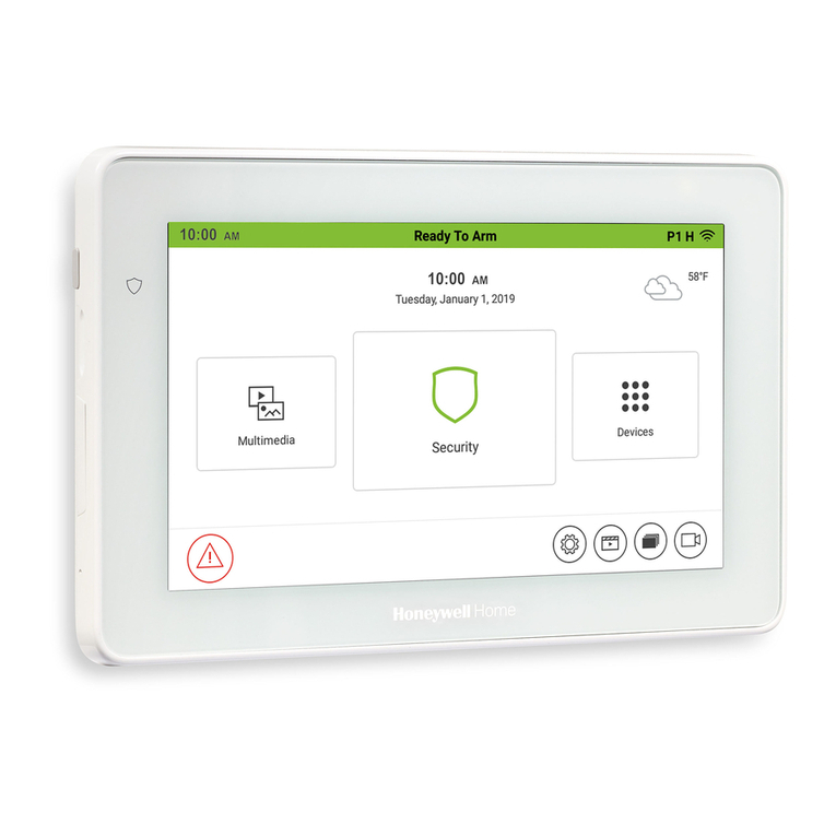
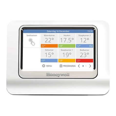
evohome Controller
(ATC928)
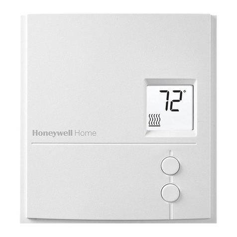
Digital Room Thermostat
(DTS92)
Wireless Relay Box (BDR91)
Wireless Cylinder Thermostat
Transceiver (CS92)
Wireless Cylinder Thermostat
Strap-on Sensor (CS92)
Wireless Cylinder Thermostat
Insertion Sensor (CS92)
Radiator Controller (HR92)
Radiator Controller (HR91)
Radiator Controller (HR80)
* Obsolete but compatible
Wireless OpenTherm Bridge
(R8810)
Mixing Valve Controller
(HM80)
* Obsolete but compatible
Underfloor Heating Controller
(HCE80 or HCC80)
evohome Controller Wall Bracket
(ATF600)
evohome Controller Table Stand
(ATF800)
Room Temperature Sensor
(HCW82)
* Obsolete but compatible
Single Zone Thermostat
(T87RF)
Room Temperature Sensor
(HCF82)
Hot Water Kit (ATF500DHW)
Icon key

1evohome Installation Guide
Thanks for choosing evohome.
evohome means more comfort, and
more control of the heating system. It’s
simple to install and easy to use.
Follow these instructions to set up the
evohome system. Devices that need to be
connected to the mains electricity supply
should be installed by a competent person.
Before you start
Make sure you have all the devices you need
for your system. If you used our ‘Design
your evohome system’ guide, match each
device to the room or zones in your plan.
It’s a good idea to carry out all the mains
electrical and other wiring work first.
In this guide
Step 1: Wire up the heating system 3
Step 2: Set up your evohome Controller 8
Step 3: Power up and bind devices 12
Step 4: System test 29
Configuration and modification 36
Appendix 39

2Step 1: Wire up the heating system
Step 2: Set up your evohome Controller
Power up the evohome Controller, connect to a WiFi network and follow the on-screen
instructions for your system
Go to Installer Menu Go to Guided Configuration Go to Home screen
You have…
a Connected Pack
+
Un-bound devices
You have…
an un-bound evohome
Controller
+
Un-bound devices
You have…
a Connected Pack
+
No additional devices
Step 3: Power up and bind devices
Power up all devices, including the battery powered ones,
and bind them to the evohome Controller
Step 1: Wire up your heating system
Connect all mains powered devices to the heating system
Step 4: Test the system
Check that all the devices are working properly

3evohome Installation Guide
In this section
Wireless Relay Box (BDR91) 4
Wireless Cylinder Thermostat (CS92) 5
Mixing Valve Controller (HM80), Underfloor Heating Controller (HCE80/HCC80),
Opentherm Bridge (R8810) 7
Step 1: Wire up the
heating system
evohome communicates using wireless on a robust 868Mhz
signal that is unaffected by common remote controls or WiFi.
Some devices need mains power or to be connected to external
equipment and it's best to wire up these items first to simplify the
binding process later in the setup. The evohome controller will
give on screen instructions when these should be powered up.
Before you power up your evohome Controller and install
the radiator controllers, it's best to install any devices
which are mains powered or need specific installation.

4Step 1: Wire up the heating system
Turn off at mains and
isolate the supply
before starting
If you’re fitting a Wireless Relay Box
(BDR91) to your boiler, zone valve
or Sundial valve, or as a Heat/cool
changeover device.
Mount the Wireless Relay Box on a non-metal
surface at least 30cm from your boiler, other
wireless devices or metallic large metal objects
Release the clip on the bottom to open the front cover
Follow the wiring diagram to connect the Wireless Relay
Box to your boiler’s thermostat terminals, zone valve
or sundial valve, and to the mains electricity supply
Replace the cover
Refer to boiler or Heat Pump instruction to locate the room thermostat
terminals, determine if the boiler required a permanent live supply.
Wireless Relay Box (BDR91)
!
BOILER
MINIMUM
30CM
REPLACE
FRONT
COVER
BOILER OR
Heat Pump

5evohome Installation Guide
Position the sensor from one quarter to a
third of the way up the cylinder.
Wire to CS92 Transceiver
Wireless Cylinder Thermostat (CS92)
If you’re fitting a Wireless Cylinder
Thermostat (CS92)
You will need to install the CS92 Transceiver and only
one of the two sensors (CS92 Strap-on Sensor or
CS92 Insertion Sensor).
To fit the CS92 Strap-on Sensor
Cut away a section of cylinder insulation
slightly larger than the sensor unit
Clean the exposed cylinder surface
Place the sensor on the cylinder surface
and secure it using the fixing strap – cut
the strap to size if it’s too long
Install the CS92 Transceiver in a suitable location
close enough for the cable from the sensor to reach
Connect the cable from the sensor
to the CS92 Transceiver
1/4 – 1/3
TOTAL
HEIGHT
45MM
80MM
MINIMUM
30CM
A x B Cy
A x B Cy

6Step 1: Wire up the heating system
Wireless Cylinder Thermostat (CS92) continued
If this sensor is used in
an unvented hot water
storage application,
the cylinder
manufacturer’s
instructions must be
followed to ensure
compliance with all
safety regulations.
If in doubt, contact the
cylinder manufacturer.
!
To fit the CS92 Insertion Sensor
Fit in the cylinder immersion well with suitable fittings
to provide strain relief and prevent accidental removal
If the sensor doesn’t fit tightly in the immersion
well fill the space with heat-conductive
compound to ensure maximum heat transfer
Install the CS92 Transceiver in a suitable location
close enough for the cable from the sensor to reach
Connect the cable from the sensor
to the CS92 Transceiver.
The wires are polarity free, so can be connected
in any order. Provide appropriate strain relief
to this end of the sensor cable as well.
DO NOT remove
existing thermostats
or high limit cut off
devices from thermal
stores, but the sensor
may be fitted in the
same pocket.
!
Wire to CS92 Transceiver
A x B Cy
A x B Cy

7evohome Installation Guide
If you’re fitting a Mixing Valve
Controller (HM80), Underfloor
Heating Controller (HCE80/HCC80),
OpenTherm Bridge (R8810)
Refer to the installation instructions
supplied with each device
Mixing Valve Controller (HM80), Underfloor Heating
Controller (HCE80/HCC80), OpenTherm Bridge (R8810)

8Step 1: Wire up the heating system
Step 2: Set up your
evohome Controller
The evohome Controller has a guided configuration
process to help you set up the zones for a single type of
system. For mixed systems (i.e. Under Floor Heating zones
plus Radiator zones) use Guided Configuration for the
larger system then “Add Zones” in the installer menu.
To add a stored hot water system use the guided configuration
Stored Hot Water option in the installer menu.
Some Heat Pumps can cool as well as heat, only
select the cooling option if it is available.
The following instructions cover the full configuring process
for a zone, but if you are using Guided Configuration your
evohome Controller will give you on-screen instructions to
bind the other components to the evohome Controller – just
follow the bind instruction for each device in this manual.
In this section
Powering up your evohome Controller 9
Language selection and WiFi configuration 10
Set-up the evohome controller for your system 11
9evohome Installation Guide
First, power up the evohome Controller
Remove the cover, remove the battery
tab and replace the cover.
Place it on the table stand or wall bracket
Once the batteries are fully charged, the evohome
Controller can be easily removed from the table stand or
wall bracket for ease of programming. After 30 minutes
the evohome Controller will emit a beep to indicate that
it should be replaced on the stand or wall bracket
Your evohome
Controller comes
with *rechargeable
batteries which are
pre-charged allowing
you to set-up the
system while off
the table stand or
wall bracket.
Place the evohome
Controller on the table
stand or wall bracket
for normal use.
*Only use the
AA rechargeable
batteries provided.
!
PULL TAB

10 Step 1: Wire up the heating system
Select a language for the evohome
controller and connect to a WiFi network
Select a language for the evohome
controller user interface
Follow the on-screen instructions to connect to a WiFi
network. This enables automatic setting of the date
and time for your location, as well as enabling remote
connectivity via an Apple or Android Smartphone.
• To configure WiFi you will need the
home WiFi network password
Instruct the homowner / user to visit
getconnected.honeywellhome.com to
create an account, register the evohome
Controller and download the app.
• To create an account and register the evohome
Controller the homeowner will need the
MAC ID and CRC which can be found:
– On a label behind the front cover
of the evohome Controller
– on screen during the WiFi set-up
– in the SETTINGS > WiFi SETTINGS menu
after set-up has been completed
If you don't have the
WiFi network details,
or the homeowner
doesn't require remote
access you can skip the
WiFi configuration and
proceed with setting up
the heating system.
WiFi can be configured
later in the SETTINGS >
WIFI SETTINGS menu.
!
Language selection and WiFi configuration
Select your store Total Connect Comfort Int

11evohome Installation Guide
Now choose the correct option for
the system you’re installing:
For a Connected Pack* and NO additional
un-bound devices we recommended
pressing ‘Home’ – then go to "Step
4: System test" on page 29.
For an un-bound evohome Controller,
PLUS additional un-bound devices
we recommended pressing ‘Guided
Configuration’ to add the un-bound
devices and follow "Step 3: Power up
and bind devices" on page 12.
For a Connected Pack*, PLUS additional
un-bound devices we recommended
pressing ‘Installation Menu’ to add the
un-bound devices and follow "Step 3: Power
up and bind devices" on page 12.
* A Connected Pack contains devices which are
already bound to the evohome Controller. Choosing
"Guided Configuration" will delete the binding from
evohome Controller and will require to be bound
again.
The Wireless Relay Box (BDR91) in a Connected
Pack is bound as a boiler controller. If you
intend to use it as a Zone Valve or SPlan/YPlan
(Sundial) Valve controller the binding must be
cleared from the Wireless Relay Box first.
Set-up the evohome controller for your system

12 Step 3: Power up and bind devices
Step 3: Power up and
bind devices
If you bought a Connected Pack only — your devices are already bound.
Go to Step 4.
If you bought an unbound evohome Controller, plus other un-bound
devices and are using ‘Guided Configuration’ follow the instructions on
your evohome Controller screen and use this section to put the devices
into binding mode.
If you bought a Connected Pack, plus other un-bound devices, you need
to power up all devices and then bind them to the evohome Controller
using the ‘Installation Menu’. It may be easier to power up and bind some
devices while they’re close to the evohome Controller – you can install
them in their assigned zones later.
Follow the instructions for the device(s) you’re going to bind. When you
bind a device to the evohome Controller the devices permanently store
the connection and there should never be a need to rebind them again –
even after a power cut.
In this section
Radiator Controllers (HR91/92) 13
Wireless Cylinder Thermostat (CS92) 16
Wireless Relay Box (BDR91A or T) to control a Boiler or Heat Pump (BDR91T) 18
Wireless Relay Box (BDR91T) to act as a Heat Cool Switch 20
OpenTherm Bridge (R8810) 21
Wireless Relay Box (BDR91A or T) to control a Zone Valve 22
Underfloor Heating Controller (HCE80 or HCC80) 24
Mixing Valve Controller (HM80) 27

13evohome Installation Guide
Power up and bind Radiator Controllers
(HR91)
Bind the Radiator Controllers (HR91)
Remove the top cover
Open the battery clip and insert the AA batteries supplied
Close the clip and replace the cover
Press the Binding button for 5 secs.
The LED will flash amber for up to 2 mins whilst
binding. Successful binding is confirmed by
LED showing continuous green for 5 seconds.
You should receive a SUCCESS message on the
evohome Controller (if not go back and re-bind)
Either press the green tick to add another
radiator to the zone. Or press the red cross if
you don’t need to add another radiator to the zone
Radiator Controllers (HR91/92)
5 SEC
2 MIN 5 SEC
If you are NOT
following GUIDED
CONFIGURATION
follow these steps
on your evohome
Controller display first:
1. Press and hold
‘Settings’ for 3
seconds
2. Press the green tick
3. Press ADD ZONE
4. Type a name for the
new zone and press
the green tick
5. Press RADIATOR
VALVE
6. If you want to control
the zone temperature
with the evohome
Controller (which
needs to be located
in that zone) press
YES, otherwise press
NO.
You must repeat these
steps for each radiator
controller.
evohome
Controller

14 Step 3: Power up and bind devices
Power up and bind Radiator Controllers
(HR92) – Your evohome Zone Kit
Bind the Radiator Controllers (HR92)
Remove the circular top cover
Open the battery clip and insert the AA batteries supplied
Close the clip and replace the cover
Press the button once − it should say UNBOUND
Press and hold the button for a further
5 seconds until it says BIND
Press the button once – it should say BINDING
You should receive a SUCCESS message on the
evohome Controller (if not go back and re-bind)
The name of the allocated zone should appear on
the HR92 display when you press the button
9
Either press the green tick to add another
radiator to the zone. Or press the red cross if
you don’t need to add another radiator to the zone
If you are NOT
following GUIDED
CONFIGURATION
follow these steps
on your evohome
Controller display first:
1. Press and hold
‘Settings’ for 3
seconds
2. Press the green tick
3. Press ADD ZONE
4. Type a name for the
new zone and press
the green tick
5. Press RADIATOR
VALVE
6. If you want to control
the zone temperature
with the evohome
Controller (which
needs to be located
in that zone) press
YES, otherwise press
NO.
You must repeat these
steps for each radiator
controller.
evohome
Controller
Radiator Controllers (HR91/HR92)
PRESS
ONCE
PRESS
AND HOLD
5 SEC
PRESS
ONCE

15evohome Installation Guide
Install the Radiator Controllers
Locate the room (zone) for the radiator controller
Slide the locking mechanism to the unlock position
Remove the adaptor from the bottom of the controller
Unscrew the black wheel fully anti-clockwise
Remove any existing control on the radiator valve
Screw the white end of the adaptor
on to the radiator valve
Push the controller fully on to the adaptor
with the screen facing towards you
Slide the locking mechanism to the locked position
REMOVE
ROTATE

16 Step 3: Power up and bind devices
Power up and bind the CS92 Transceiver
On the CS92 Transceiver
Remove the CS92 Transceiver cover, pull out
the battery tab and replace the cover
On the CS92 Transceiver press and hold the
button for 5 seconds. The green light should
come on and the red light should flash
Press the button again
You should receive a SUCCESS message on the
evohome Controller (if not go back and re-bind)
Choose the correct hot water valve type for the system
you’re installing and follow the on screen instructions
To control a stored hot water system you first need to bind
the CS92 Transceiver and then bind the Wireless Relay
Box (BDR91) that is controlling the hot water valve.
If you are NOT
following GUIDED
CONFIGURATION
follow these steps
on your evohome
Controller display first:
1. Press and hold
“Settings” for 3
seconds
2. Press the green tick
3. Select GUIDED
CONFIGURATION
4. Press STORED
HOT WATER
CONFIGURATION
5. Press the green tick
evohome
Controller
Wireless Cylinder Thermostat (CS92)
PRESS
ONCE
PULL
TAB
PRESS
AND HOLD
5 SEC

17evohome Installation Guide
To bind the Wireless Relay Box (BDR91A
or T) controlling the hot water valve
On the Wireless Relay Box, press and hold the
button for 15 seconds (until the red LED blinks
rapidly) to clear any previous binding data
Press and hold the button again for 5 seconds
(until the red LED blinks slowly)
On the evohome Controller press
the green bind button
You should receive a SUCCESS message on the
evohome Controller (if not go back and re-bind)
You may need to refer
to the wiring diagrams
in the Appendix
!
The Wireless Relay
Box in a Connected
Pack is bound as a
boiler controller. If you
intend to use it as a
SPlan/YPlan Valve
controller the binding
must be cleared from
the Wireless Relay Box
first – as described in
step 1.
!
PRESS
AND HOLD
15 SEC
PRESS
AND HOLD
5 SEC

18 Step 3: Power up and bind devices
Power up and bind a Wireless Relay
Box (BDR91A or T) to control a boiler or
buffer tank secondary pump.
Make sure the Wireless Relay Box (BDR91A or T) is
wired to the boiler and powered up.
To bind the Relay Box
Press and hold the button for 15 seconds (until the red
LED blinks rapidly) to clear any previous binding data
Press and hold the button again for 5 seconds
(until the red LED blinks slowly)
On the evohome Controller press
the green bind button
You should receive a SUCCESS message on the
evohome Controller (if not go back and re-bind)
If you are NOT
following GUIDED
CONFIGURATION
follow these steps
on your evohome
Controller display first:
1. Press and hold
‘Settings’ for 3
seconds
2. Press the green tick
3. Press SYSTEM
DEVICES
4. Press APPLIANCE
CONTROL
5. Press WIRELESS
RELAY
evohome
Controller
Wireless Relay Box (BDR91)
PRESS
AND HOLD
15 SEC
PRESS
AND HOLD
5 SEC
Other manuals for Evohome
1
This manual suits for next models
2
Table of contents
Other Honeywell Home Home Automation manuals

Honeywell Home
Honeywell Home TUXEDOW Assembly instructions

Honeywell Home
Honeywell Home Tuxedo Touch TUXWIFIS Assembly instructions

Honeywell Home
Honeywell Home DCP917 Series User manual

Honeywell Home
Honeywell Home RLV3150 User manual

Honeywell Home
Honeywell Home resideo evohome ATC928G2000 User manual