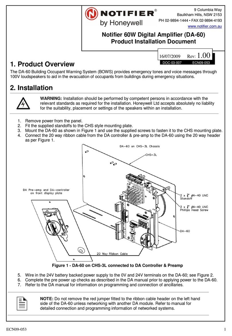
Honeywell X-618 User manual

M_2000061032_EN_3.2
X-618 Public Address System
Installation Manual
2000061140 X
-
618 Installation Manual_FCC_V1.
2
3


Copyright
© 2018 Life Safety A/V (Guangzhou) Co., Ltd. All rights reserved.
No part of this document may be reproduced in any form without the written permission of the
copyright owner.
Disclaimer
The contents of this document are subject to revision without notice due to continued progress in
methodology, design, and manufacturing. Honeywell shall have no liability for any error or damage
of any kind resulting from the use of this document.
Trademark List
All trademarks mentioned herein are the property of their respective owners. These are shown in
the document Trademark Information.


i
Precautions
Danger
This sign reminds users of “dangerous voltage” on the
product.
Caution
This sign reminds users of important instructions
attached to the product.
Safety
guideline
In order to prevent electric shock, this equipment plug
shall not be used as conductor to extend power supply
line.
Do not block the equipment’s ventilation opening or put
other equipment on it.
Safety
guideline
Protect this equipment against rainwater or moisture so
as to avoid fire or electric shock.
Unpacking
After removing the amplifier from the carton, inspect for any exterior damage to the unit. If damage
is noted, notify the carrier at once so that a claim can be justified. Save all packing material. This
is important when the claim is processed.
Ventilation
To offset heat generated by the unit, it is necessary to provide ample ventilation around the unit.
Avoid blocking or impeding the ventilation holes on the unit. To prevent unnecessary problems,
install the unit in a place free from any vibrations, direct sunlight, humidity or dust circulation.
Prevent liquids or other materials to enter cabinet
If the unit gets wet or any foreign material enters the amplifier cabinet, immediately disconnect the
AC power cord and consult your dealer or qualified technician.
Important Safety Instructions
•Read these instructions.
•Keep these instructions.
•Heed all warnings.
•Follow all instructions.
•Do not use this apparatus near water.
•Clean only with a dry cloth.
•Do not block any ventilation openings. Install in accordance with the manufacturer’s instructions.
•Do not install on or near any heat sources such as radiators, heat registers, stoves or other apparatus
(including amplifiers) that produce heat.
•Do not defeat the safety purpose of the polarized or grounding-type plug. A polarized plug has two blades
with one wider than the other. A grounding type plug has two blades and a third grounding prong. The wide

ii
blade or the third prong are provided for your safety. If the provided plug does not fit into your outlet, consult
an electrician for replacement of the obsolete outlet.
•Protect the power cord from being walked on or pinched particularly at plugs, convenience receptacles, and
the point where they exit from the apparatus.
•Only use the attachments/accessories specified by the manufacturer.
•Use only with the cart, stand, tripod, bracket or table specified by the manufacturer,
or sold with the apparatus. When a cart is used, use caution when moving the
cart/apparatus combination to avoid injury from tip-over.
•Unplug this apparatus during lightning storms or when unused for long periods of
time.
•Refer all servicing to qualified service personnel. Servicing is required when the
apparatus has been damaged in any way such as power supply cord or plug is
damaged, liquid has been spilled or objects have fallen into the apparatus, the apparatus has been exposed
to rain or moisture, does not operate normally, or has been dropped.
•Apparatus shall not be exposed to dripping or splashing and no objects filled with liquids, such as vases,
shall be placed on the apparatus.
•WARNING – To reduce the risk of fire or electric shock, do not expose this apparatus to rain or moisture.
•The mains plug is used as disconnecting device and shall remain readily operable.
•The apparatus is unsuitable for use in air-handling spaces.
•This device complies with part 15 of the FCC Rules. Operation is subject to the following two conditions: (1)
This device may not cause harmful interference, and (2) this device must accept any interference received,
including interference that may cause undesired operation.
•Class I apparatus shall be connected to a mains socket outlet with a protective earthing connection.
Network Security
Placement
•Please put the device in a safe place, lock the cabinet and keep the keys well.
•The access control system of the central control room should be under strict management.
•Any person except authorized maintainer is forbidden to disassemble or change parts of device.
•It is forbidden to communicate X-618 system with third party system unless updating the configuration.
Password Precaution
•Please change the password during the system deployment.
•Users need to change the password regularly.
•The password with six numbers is preferred.

1
Table of Contents
Precautions.............................................................................................................................................i
Unpacking ................................................................................................................................................ i
Ventilation................................................................................................................................................. i
Prevent liquids or other materials to enter cabinet ................................................................................... i
Important Safety Instructions ...............................................................................................................i
Network Security...................................................................................................................................ii
Placement ............................................................................................................................................... ii
Password Precaution .............................................................................................................................. ii
Table of Contents..................................................................................................................................1
Preface ...................................................................................................................................................2
Brief Introduction.............................................................................................................................................. 2
Intended Reader .............................................................................................................................................. 2
Relevant Documents........................................................................................................................................ 2
Use Instructions ............................................................................................................................................... 2
1 System Overview .............................................................................................................................3
2 Preparation for Installation ...........................................................................................................96
Gathering Information .................................................................................................................................... 96
Preparing Tools.............................................................................................................................................. 96
Preparing Auxiliary Materials ......................................................................................................................... 96
Preparing Cables and Auxiliary Equipment.................................................................................................... 96
Packing List Inspection ................................................................................................................................ 118
3 System Installation ......................................................................................................................129
Installation Requirements of Cabinet ........................................................................................................... 129
Installing the Devices in the Appliance Cabinet ......................................................................................... 1310
Installing the DCS, NRI and DA into the associated appliance cabinet ............................................. 1310
Installing the X-NPMS on a Cabinet .................................................................................................. 1411
Connecting the X-618 System Components ..............................................................................................1512
Connecting the Sound Source Equipment to the DCS or NRI........................................................... 1512
Connecting the DCS to the DA.......................................................................................................... 1613
Connecting the Dry Contacts (Optional)............................................................................................ 1916
Connecting the Noise Detector (Optional)......................................................................................... 2218
Connecting the Loudspeakers........................................................................................................... 2421
Connecting the DCS and NRI to the NPM......................................................................................... 2521
Connecting the Power Supply Cables........................................................................................................ 2622
Connecting the DCS and the NRI Main and Standby Power Supply Cables..................................... 2722
Connecting the DA Main and Standby Power Supply Cables ........................................................... 2823
Connecting the NPM Power Supply Cable........................................................................................ 2924
Connecting the NRI with the Telephone Interface...................................................................................... 2925
4 Installation Inspection ...............................................................................................................3126
Inspection................................................................................................................................................... 3126
Manual Setting ........................................................................................................................................... 3126
Inquiring the device IP....................................................................................................................... 3126
Impedance Calibration ...................................................................................................................... 3126

2
Preface
Thank you for purchasing the X-618 Public Address System. Please carefully read this manual
prior to system use to ensure correct use of the system.
Brief Introduction
This manual describes the appearance, installation, and wiring of the X-618 Public Address
System equipment. The manual includes the following chapters:
Chapter 1: System Overview
Describes the X-618 Public Address System structure and product assembly.
Chapter 2: Preparation for Installation
Describes preparing to install the X-618 Public Address System.
Chapter 3: System Installation
Describes installing the X-618 Public Address System along with related precautions.
Chapter 4: Installation Inspection
Describes inspecting the installation of the X-618 Public Address System and system
commissioning.
Intended Reader
This manual is mainly for personnel who are to install, operate, and maintain the X-618
Broadcasting System.
Relevant Documents
The following documents can be used as a reference when reading this manual:
•X-618 Public Address System Product Description
•X-618 Public Address System Configuration Manual
•X-618 Public Address System Operation Manual
Use Instructions
•All content including figures in this manual are to be used only for reference.
•The product may be subject to change without notice.
•It is recommended that all warnings and precautions in this manual are read.
•Carefully read this manual before using the product and keep it as a reference for future use.
•This manual has been reviewed and its accuracy is ensured. In case of any doubt or dispute of
the product description, the final interpretation given by Life Safety A/V (Guangzhou) Co., Ltd.
shall prevail.
Life Safety A/V (Guangzhou) Co., Ltd. is not liable for any consequences caused by user
mistakes when using the product or user misunderstandings of the manual content.

3
1 System Overview
The X-618 Public Address System provides a complete multiple sound source public audio
management solution. Centralized network management is achieved through the system software,
and all system states are monitored. The X-618 Public Address System is hereby referred to as the
“X-618” throughout the remainder of this manual.
The X-618 includes the following product components:
•X-DCS3000 Digital Integrated System Manager
The X-DCS3000 Digital Integrated System Manager is hereinafter referred to as the “DCS”.
When describing specific installation requirement, the X-DCS3000 is referenced.
The DCS is X-618 control equipment, is designed for expanding the number of loudspeaker
zones, and can support multiple sound source files for broadcasting. The system integrates
with functions such as the sound source file the storage system, the network audio
broadcasting system, the loudspeaker zone control system, and the system for monitoring and
diagnosing faults.
•X-DA1500/DA2250/DA4125 High Efficiency Power Amplifier
The X-DA1500/DA2250/DA4125 High Efficiency Power Amplifier is hereinafter referred to as
the “DA” or the “X-DA1500/DA2250/DA4125”.
In the X-618 system, the DA is used to amplify audio signal power and drive many
broadcasting loudspeakers.
•X-NPMS Configurable Network Paging Console
The X-NPMS Programmable Network Paging Console is used to page zones and control
broadcasts for the X-618 on an Ethernet network.
•X-NRI Network Resource Interface
The X-NRI Network Resource Interface is hereinafter referred to as the “NRI” or “X-NRI”.
The X-NRI is the external interface expansion control equipment in the X-618. It has multiple
audio interfaces and control ports enabling it to send audio and control signals through the
Ethernet network to the X-618 system.

4
The X-DCS3000 is capable of connecting to 8 main amplifier channels and 2 standby amplifier
channels. See connection diagrams in Figure 1- 3 for 4 amplifier channel system.

5

6
Figure 1 Connection Schematic Diagram of X-DCS3000 and X-DA1500

7
Figure 2 Connection Schematic Diagram of X-DCS3000 and X-DA2250

8
Figure 3 Connection Schematic Diagram of X-DCS3000 and X-DA4125

9
2 Preparation for Installation
Before installing the system, appropriate preparation is required to ensure a smooth installation
process.
•Gathering Information
•Preparing Tools
•Preparing Auxiliary Materials
•Preparing Cables and Auxiliary Equipment
•Packing List Inspection
Gathering Information
Installation personnel are required to be familiar with functional components of the X-618 product
equipment. It is recommended to first read the product information found in the X-618 Public
Address System Product Description manual.
Preparing Tools
Prepare the following tools before installing the system equipment:
•Electrostatic wrist band
•Electrostatic gloves
•Wire stripping pliers
•Wire cutting pliers
•RJ45 crimp tool
•Slotted screwdriver (M2)
•Phillips screwdriver (P1)
Preparing Auxiliary Materials
Prepare the following auxiliary materials before installing the system equipment:
•Insulating tape
•Wire buckles
•Cable labels
•Plastic ties
Preparing Cables and Auxiliary Equipment
Note:
It is recommended to select high quality and professional-grade transmission cables for large scale
loudspeaker systems.
Before installing the equipment, prepare the following:
•CAT-5 Ethernet Cable
Cable requirements should not exceed 100m with diameters of 0.51mm (wire gauge of
24AWG). Shielded twisted pair cables are recommended. If the distance between devices is

10
less than 30 meters, the cable can be straight through or crossover. If the distance between
devices is more than 30 meters, the cable must be a crossover.
Refer to Table 1 for the Ethernet pin types.
Table 1 RJ45 Cable Pin Definition Descriptions
PIN Type Legend
1 TX+
2 TX-
3 RX+
4 No pin
5 No pin
6 RX-
7 No pin
8 No pin
•1070V audio connection cable
This cable is used to connect the DCS to the DA as well as the DCS to the loudspeakers in the
broadcasting zones. Shielded cables with a cross-section of 1.3mm
2
(wire gauge of 16AWG)
are recommended.
•DA backup power supply cable
This cable is used to connect DCS, DA to DC backup power supply. The wire of 9AWG is
recommended for DA, and the wire of 16AWG is recommended for DCS.
•Power amplifier audio input cable
Audio input cables are provided in the package containing the DA, but the lengths of these
cables are limited. If these cables cannot meet the requirements of the system wiring situation,
users need to obtain or create appropriate cables themselves. Please prepare such audio
input cables with the specifications as listed in Table 2. This cable should be a direct
connection.
Table 2 Power Amplifier Input Cable Pin Definition Descriptions
PIN Type Legend
1 Balanced positive input of CH2
2 Balanced negative input of CH2
3
DA fault information output
•When the DA is working properly, the
output voltage is VCC(12V-24V)
•When the DA faults, is protected, or
undergoes self-testing, the output
voltage is GND(0V)
4 Balanced positive input of CH1
5 Balanced negative input of CH1
6 GND(0V)
7 VCC (12V-24V, powered by an external
device)

11
PIN Type Legend
8
Self-test port
•When the DA output voltage is VCC
(12V-24V), the DA is being self-tested.
•When the DA has no input voltage, the
DA is working normally.
•Power amplifier output cables
Unshielded cables with a cross-section of 1.3mm
2
(wire gauge of 16AWG) are recommended
for the power amplifier output.
•XLR audio input cable
Shielded pair cables with a cross-section of 0.3~0.5mm
2
are recommended for connecting
external audio resource.
Table 3 X-DCS3000 XLR Input Terminal Pin Definition Descriptions
PIN Type Legend
1 Grounding wire(Shielded layer of cable)
2 Hot end (Positive)
3 Cold end (Negative)
•Dry contact input/output cables and related external equipment (optional)
The necessity of dry contact connections depends on the system situation. If the DCS and
external equipment, such as 3-wire volume controllers and 4-wire volume controllers, must be
connected through dry contacts, this equipment and the appropriate cables must be prepared
beforehand.
•Noise detector (optional)
When environmental noise is present and the volume of broadcasts need to be automatically
regulated, you will need a noise detector and the appropriate cables. For connecting the X-
DCS3000 with X-ND100, the maximum cable distance between the DCS and noise detector
should be no longer than 1000m, and twisted pair cables with a cross-section of 1.3mm
2
(wire
gauge of 16AWG) must be used.
•Monitoring module cable of end-of-line (optional)
If monitoring is required for faults in the speaker lines, use the X-EOL. The distance between
the monitoring module and the DCS should be less than 1000m, and twisted pair cables with a
cross-section of 1.3mm
2
(wire gauge of 16AWG) must be used.
Packing List Inspection
Please check packages carefully for any damage. Use the packing list to ensure that you have all
your components. Contact your carrier/supplier if there are any issues.

12
3 System Installation
This chapter describes the system equipment installation, cable connections, and relevant
precautions.
•Installation Requirements of Cabinet
•Installing the Devices in the Appliance Cabinet
•Installing the NPM on a Fixed Surface (Optional)
•Connecting the X-618 System Components
•Connecting the Power Supply
Note:
•The electricity and power sources must be turned off when performing the following tasks to
avoid electric shocks and damage to the equipment.
•Turn off all equipment power supply switches prior to wiring.
•Connect the wiring terminals and tighten the screws.
•The power supply cables and signal data lines must be separated, and cannot be laid in the
same slot or piping.
•To avoid interference, the speaker lines and the power should be separated.
•Control signal cables must be positioned away from 1070V audio or power supply cables to
avoid signal interference.
•Appropriate materials, such as plastic ties, must be used for all connection cables. When
moving the cables, prevent the power supply cables from coming in contact with the signal data
cables.
•Install appropriate electrical cable bushings at the cabinet opening before installing the cables
in the appliance cabinets.
•The spaces reserved for the cables at the cabinet opening must be blocked if these spaces are
not used.
Installation Requirements of Cabinet
The X-618 system needs to be installed in a standard 19” cabinet. The ground wire is required to
be connected to the cabinet. There are specialized earth wires at the door and the bottom of
cabinet. Please refer to following steps for installation:
The cabinet door shaft contains one yellow screw as shown in Figure 4, identified with marker
①
.
Figure 4, marker
②
, represents another grounding terminal in the same position in the cabinet.
Connect the two terminals with a wire.
Connect the grounding screw of all devices in the cabinet to the grounding terminal. For safety
reasons, it is recommended to connect an external specified grounding terminal to the one on the
cabinet.

13
Figure 4 Schematic Diagram of Cabinet Grounding
All the devices of this system are equipped with a specialized grounding screw, marked with the
icon . After installing in the cabinet, cabinet grounding and device grounding should be
connected by a soft cable with a cross-section of 1.5mm
2.
Caution:
To prevent a grounding loop, be careful to not let a short circuit occur over the grounding wires.
During the installation of amplifier, to ensure a better cooling performance, 1U blind plate is
recommended between the amplifier and device.
Before installation, inner space of the cabinet should be arranged based on the actual number and
types of devices. The bottom plate needs to be installed, and the empty spaces can be filled with
blind disk.
The X-618 spare list includes foot for the bottom of the device, which is used for desktop
installation. Make sure there is no foot installed at the bottom of the device before installation.
Installing the Devices in the Appliance Cabinet
Installing the DCS, NRI and DA into the associated appliance cabinet
Installing the DCS, NRI and DA into the cabinet is done as follows:
1. Install brackets on the left and right sides of the DCS, as shown in Figure 5.
Figure 5 Schematic Diagram of the DCS Bracket Installation

14
2. Put the DCS appliance into the cabinet, and tighten the screws to secure the unit, as shown in
Figure 6.
Figure 6 Schematic Diagram of Installing the DCS in the Cabinet
3. Install the brackets beside X-NRI Network Resource Interface, and install in the cabinet.
4. Install the brackets beside amplifier, and install in the cabinet.
5. After all installation, use screws to secure the device in the cabinet.
Installing the X-NPMS on a Cabinet
The X-NPMS Configurable Network Paging Console and the key module extensions X-K4 or X-K8
can be installed in the cabinet according to customer’s requirements. Before installation, the X-
NPMS and extension key module should be installed together first.
The installation process is as follows:
1. Use cables to connect the devices. Pay attention to the direction.
2. Put the bracket between the devices as shown in Figure 7, and fix it with standard
configuration screws.
Figure 7 Installation Diagram of X-NPM and Extension Key Module
Other manuals for X-618
5
This manual suits for next models
1
Table of contents
Other Honeywell Amplifier manuals

Honeywell
Honeywell KMA 28 User manual

Honeywell
Honeywell Fire-Lite Alarms ECC-50DA User manual

Honeywell
Honeywell Notifier DA-60 Technical manual

Honeywell
Honeywell X-DA4125 User manual

Honeywell
Honeywell NOTIFIER AA Series User manual

Honeywell
Honeywell X-618 Quick start guide

Honeywell
Honeywell R7824 Operation manual

Honeywell
Honeywell Notifier DA-120 Technical manual

Honeywell
Honeywell Gamewell-FCI AA-100 User manual

Honeywell
Honeywell BENDIX/KING KMA28 User manual