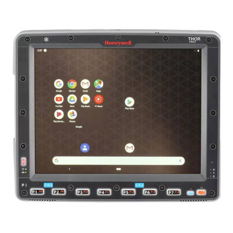
Honeywell Thor VM2 User manual

Thor™ VM2
Vehicle-Mounted Computer
Microsoft®Windows®Embedded Standard 2009 Operating System
Reference Guide

Disclaimer
Honeywell International Inc. (“HII”) reserves the right to make changes in specifications and other information contained in this
document without prior notice, and the reader should in all cases consult HII to determine whether any such changes have
been made. The information in this publication does not represent a commitment on the part of HII.
HII shall not be liable for technical or editorial errors or omissions contained herein; nor for incidental or consequential damages
resulting from the furnishing, performance, or use of this material.
This document contains proprietary information that is protected by copyright. All rights are reserved. No part of this document
may be photocopied, reproduced, or translated into another language without the prior written consent of HII.
© 2012-2013 Honeywell International Inc. All rights reserved.
Web Address: www.honeywellaidc.com
RFTerm is a trademark or registered trademark of EMS Technologies, Inc. in the United States and/or other countries.
Microsoft®Windows, ActiveSync®, MSN, Outlook®, Windows Mobile®, the Windows logo, and Windows Media are
registered trademarks or trademarks of Microsoft Corporation.
Intel®and Atom™ are trademarks or registered trademarks of Intel Corporation or its subsidiaries in the United States and
other countries.
Summit Data Communications, the Laird Technologies Logo, the Summit logo, and "Connected. No Matter What" are
trademarks of Laird Technologies, Inc.
The Bluetooth®word mark and logos are owned by the Bluetooth SIG, Inc.
Symbol®is a registered trademark of Symbol Technologies. MOTOROLA, MOTO, MOTOROLA SOLUTIONS and the
Stylized M Logo are trademarks or registered trademarks of Motorola Trademark Holdings, LLC and are used under license.
Freefloat, Link*One, Key*One and Access*One are trademarks of Freefloat, Mölndalsvägen 30B, SE-412 63Gothenburg,
Sweden.
Qualcomm®is a registered trademark of Qualcomm Incorporated. Gobi is a trademark of Qualcomm Incorporated.
OneClick Internet is WebToGo’s patented connection manager customized for Honeywell mobile devices. OneClick Internet
documentation is copyright 2010 by WebToGo and modified by Honeywell with WebToGo’s express permission.
Verizon®is a registered trademark of Verizon Trademark Services LLC.
T-MOBILE®is a registered trademark of Deutsche Telekom AG.
AT&T®is a registered trademark of AT&T Intellectual Property.
Acrobat®Reader © 2013with express permission from Adobe Systems Incorporated.
Other product names or marks mentioned in this document may be trademarks or registered trademarks of other companies
and are the property of their respective owners.
Patents
For patent information, please refer to www.honeywellaidc.com/patents.
Limited Warranty
Refer to www.honeywellaidc.com/warranty_information for your product’s warranty information.


Table of Contents
Chapter 1 - Introduction 1-1
About this Guide 1-1
Components 1-2
Front View 1-2
Back View with Quick Mount Smart Dock 1-3
Access Panels 1-3
Chapter 2 - Hardware 2-1
System Hardware 2-1
802.11a/b/g/n Wireless Client 2-1
Central Processing Unit 2-1
Input/Output Components 2-2
System Memory 2-2
Video Subsystem 2-2
Audio Interface 2-2
Card Slots 2-2
CompactFlash (CF) Slot 2-2
Secure Digital (SD) Slot 2-2
Bluetooth EZPair 2-3
WWAN 2-3
GPS 2-3
Power 2-4
Vehicle DC Power Supply 2-4
External AC Power Supply 2-4
Uninterruptible Power Supply 2-4
Backup Battery 2-5
Fuse 2-5
Power Management Modes 2-6
Full On Mode 2-6
Standby Mode 2-6
System Standby Wakeup Events 2-6
Hibernate Mode 2-6
System Hibernate Wakeup Events 2-6
Off Mode 2-7
Power Configuration 2-7
AC/DC 2-7
IgnitionControl 2-7
Auto-On 2-7
i

UPS 2-7
External Connectors 2-8
Serial Connector (COM1 and COM2) 2-9
Pinout 2-9
Screen Blanking 2-10
Serial Cable 2-10
Screen Blanking Box 2-11
Screen Blanking with Switch 2-11
USB Connector 2-12
USB Dongle Cable 2-13
D9 Male Connector 2-13
USB Host Connector 2-14
USB Client Connector 2-14
Power Supply Connector 2-15
CANbus / Audio Connector 2-16
Headset Adapter Cable 2-17
D15 Female Connector 2-17
Quick Connect Headset Connector 2-18
CANbus Cable 2-19
D15 Female Connector 2-19
9-Pin J1939 (Deutsch) Connectors 2-20
Antenna Connections 2-21
Antenna Connector 2-21
Internal WiFi Antenna 2-21
External WiFi Antenna 2-21
Vehicle Remote Antenna 2-21
Keyboard Options 2-22
Integrated Keypad 2-22
Keypad LEDs 2-22
Blue LED 2-22
Orange LED 2-23
95-Key Keyboard 2-23
Keyboard Backlight 2-23
USB Keyboard / Mouse 2-24
LED Functions 2-25
System LEDs 2-25
SYS (System Status) LED 2-26
UPS Status LED 2-27
Charge Level 2-27
Charging State 2-27
ii

SSD (Solid State Drive) LED 2-27
Connection LEDs 2-28
WWAN LED 2-28
WiFi LED 2-28
Bluetooth LED 2-28
Keyboard LEDs 2-29
Blue LED 2-29
Orange LED 2-29
Programmable LED 2-29
Display 2-30
Touch Screen 2-30
Screen Blanking 2-30
Display Backlight Control 2-30
Disconnect UPS Battery 2-31
Install SD Card 2-33
Install SIM Card 2-35
Field Replaceable Front Panel 2-37
Replace Front Panel 2-37
Chapter 3 - Software 3-1
Microsoft Windows Setup and Configuration 3-1
Drive C Folder Structure 3-2
Software Loaded on Drive C 3-2
Programs Loaded on Drive C 3-3
Honeywell RFTerm (Optional) 3-3
Summit Client Utility 3-3
Freefloat Link*One Wedge (Optional) 3-3
Freefloat Access*One TE (Optional) 3-3
Freefloat Key*One 3-3
Control Panel 3-4
About 3-4
Bluetooth 3-5
Bluetooth Devices 3-7
Discover 3-8
Stop Button 3-8
Bluetooth Device List 3-9
Clear Button 3-9
Bluetooth Device Menu 3-10
Right-Click Menu Options 3-10
Bluetooth Device Properties 3-10
iii

Settings 3-11
Turn Off Bluetooth 3-11
Options 3-12
Reconnect 3-13
Options 3-14
About 3-16
Using Bluetooth 3-17
Initial Configuration 3-17
Subsequent Use 3-18
Bluetooth Indicators 3-19
Bluetooth Bar Code Reader Setup 3-20
Thor VM2 with Label 3-20
Thor VM2 without Label 3-21
Bluetooth Beep and LED Indications 3-22
Bluetooth Printer Setup 3-22
Easy Pairing and Auto-Reconnect 3-22
Display 3-23
Options 3-24
5V on COM1 3-24
5V on COM2 3-24
Touch Screen Disable 3-24
Keyboard Backlight 3-24
USB Powered in Standby 3-24
Power Options 3-25
Power Schemes 3-25
AC/DC 3-26
Thor VM2 is Off 3-26
Thor VM2 is On 3-26
Ignition Control - Ignition On 3-27
Thor VM2 is Off and Vehicle Ignition is Switched to On 3-27
Thor VM2 is On and Vehicle Ignition is Switched to On 3-27
Ignition Control - Ignition Off 3-28
Thor VM2 is Off and Vehicle Ignition is Off 3-28
Thor VM2 is On and Vehicle Ignition is Switched to Off 3-28
Auto-On 3-30
Thor VM2 is Off 3-30
Thor VM2 is On 3-30
UPS 3-31
Thor VM2 is Off 3-31
Thor VM2 is On 3-31
iv

Power Meter 3-32
Advanced 3-33
Hibernate 3-34
Programmable Key 3-35
KeyMap Tab 3-36
Remap a Single Key 3-36
Remap a Key to a Unicode Value 3-36
Remap a Key Sequence 3-37
Remap a Key to a Sequence of Unicode Values 3-37
Remap a Key to a Special Function 3-37
Remap an Application 3-38
Remap a Command 3-38
LaunchApp Tab 3-39
RunCmd Tab 3-40
Screen Control 3-41
Screen Blanking 3-42
Screen Rotation 3-43
Sounds 3-44
User Accounts 3-45
Wi-Fi 3-45
Bar Code Readers 3-46
Scanner Wedge 3-46
Touch Screen Calibration 3-47
BIOS 3-48
Accessing the BIOS Setup 3-48
Boot Order 3-48
Exiting BIOS Setup 3-48
The Thor VM2 Recovery DVD 3-49
Upgrading the Thor VM2 3-49
Chapter 4 - Wireless Network Connections 4-1
Network Connections Control Panel 4-1
Summit Wireless Network Configuration 4-1
Important Notes 4-1
Summit Client Utility 4-2
Help 4-2
Summit Tray Icon 4-2
Wireless Zero Config Utility 4-3
How To: Use the Wireless Zero Config Utility 4-3
How to: Switch Control to SCU 4-3
v

Main Tab 4-4
Admin Login 4-5
Profile Tab 4-6
Buttons 4-7
Profile Parameters 4-8
Status Tab 4-10
Diags Tab 4-11
Global Tab 4-12
Custom Parameter Option 4-13
Global Parameters 4-14
Logon Options 4-17
Single Signon 4-18
Pre-Logon Connection 4-18
Sign-On vs. Stored Credentials 4-20
How to: Use Stored Credentials 4-20
How to: Use Sign On Screen 4-20
How to: Use Windows Username and Password 4-21
Windows Certificate Store vs. Certs Path 4-22
User Certificates 4-22
Root CA Certificates 4-22
How To: Use the Certs Path 4-22
How To: Use Windows Certificate Store 4-22
Configuring the Profile 4-24
No Security 4-25
WEP 4-26
LEAP 4-28
PEAP/MSCHAP 4-30
PEAP/GTC 4-32
WPA/LEAP 4-34
EAP-FAST 4-36
EAP-TLS 4-38
WPA PSK 4-41
Certificates 4-42
Generating a Root CA Certificate 4-43
Installing a Root CA Certificate 4-46
Generating a User Certificate 4-48
Exporting a User Certificate 4-50
Installing a User Certificate 4-53
OneClick Internet 4-55
Preparing for Initial Use on the Thor VM2 4-55
vi

Install SIM Card 4-55
Load Firmware 4-55
Activation 4-55
Using OneClick Internet 4-58
How To: Connection Management 4-58
Menu Buttons 4-59
Radio Button 4-59
StatisticsButton 4-59
Update Button 4-59
Help Button 4-59
Settings Button 4-60
Profile Tab 4-61
Buttons 4-62
Parameters 4-62
Network Tab 4-63
Network with SIM Card 4-63
CDMA Network 4-65
History Tab 4-66
PIN Tab 4-66
Activate/Deactivate PIN 4-66
Change PIN 4-67
Info Tab 4-68
Firmware Tab 4-69
Activation on CDMA 4-70
General Tab 4-71
Application Tab 4-72
Application Buttons 4-73
SMS 4-73
Folder 4-74
Settings 4-74
New SMS 4-74
Reply 4-75
Forward 4-75
Move SMS... 4-75
Delete 4-75
Send/Receive 4-75
Addresses 4-75
Web Browser 4-76
Email 4-76
GPS 4-76
vii

About 4-78
System Requirements 4-78
Supported Languages 4-78
Installing or Upgrading OneClick Internet 4-78
Installation 4-79
OneClick Internet Connection Manager 4-82
Connection Management 4-82
Information Buttons 4-83
Chapter 5 - Key Maps 5-1
Integrated Keypad 5-1
External Keyboard 5-2
Chapter 6 - Technical Specifications 6-1
Thor VM2 6-1
Quick Mount Smart Dock 6-2
Dimensions 6-2
Thor VM2 6-2
Quick Mount Smart Dock 6-2
Environmental Specifications 6-3
Thor VM2 and Quick Mount Smart Dock 6-3
Network Card Specifications 6-4
Summit 802.11 a/b/g/n 6-4
Bluetooth 6-4
Chapter 7 - Technical Assistance 7-1
viii

Chapter 1 - Introduction
The Thor VM2 Vehicle Mount Computer (VMC) is a rugged, vehicle mounted computer running a Microsoft®
Windows®Embedded Standard 2009 operating system and capable of wireless data communications from a fork-lift truck or
any properly configured vehicle. Wireless communications are supported over a 802.11 WLAN network and, optionally, over a
WWAN network. The optional Bluetooth®module supports Bluetooth printers and scanners.
Caution
Before shipping the Thor VM2, the internal UPS battery must be disconnected.
The Thor VM2 is designed for use with a vehicle Quick Mount Smart Dock. The dock installs in the vehicle and connects to
vehicle power. The dock provides conditioned input power for the Thor VM2. Peripheral connections are on the dock. The Thor
VM2 is designed to easily be removed from the dock with a latch on the lower rear of the Thor VM2 housing. Since the dock
remains attached to the vehicle, the Thor VM2 computer can easily be moved from one vehicle equipped with a Quick Mount
Smart Dock to another vehicle equipped with a Quick Mount Smart Dock.
The Thor VM2 contains a UPS battery which, when fully charged, can power the Thor VM2 for a minimum of 30 minutes. This
can be when the Thor VM2 is not attached to a Quick Mount Smart Dock or when the Thor VM2 is attached to a dock but the
vehicle power is interrupted, such as when the vehicle battery is being changed.
The Thor VM2 can be used with or without an external keyboard. There are 5 programmable keys (P1 - P5)on the front bezel
and, when used with the Orange modifier key, provide 5 additional programmable keys (P6 - P10).
Contact Technical Assistance for information on the latest upgrades for your Thor VM2.
About this Guide
This Thor VM2 Reference Guide provides instruction for the system administrator to follow when configuring a Thor VM2.
This reference guide has been developed for a Thor VM2 with a Microsoft®Windows®Embedded Standard operating system.
1-1

Components
Front View
1. Power Button
2. Speakers
3. Microphone
1-2

Back View with Quick Mount Smart Dock
1. Antenna Connectors (on Thor VM2)
2. SIM card Access Panel (on Thor
VM2)
3. COM1 Connector (on Dock)
4. COM2 Connector (on Dock)
5. USB Connector (on Dock)
6. CAN/Audio Connector (on Dock)
7. Quick Release Handle (On Thor
VM2)
8. Provision for Padlock (on Thor
VM2)
9. Provision for Laptop Security Cable
(on Thor VM2)
10. Power Switch (on Dock)
11. Power Connector (on Dock)
12. Fuse (on Dock)
13. SD Card Access Panel (On Thor
VM2)
14. Strain Relief Clamps (on Dock)
15. RAM Ball (on Dock)
Access Panels
Access Panel Door is labeled with SSD and SD.
1. CompactFlash Hard Drive
2. SD (Secure Digital) Memory Card Slot
Access Panel Door is labeled with SIM.
1. SIM card slot for WWAN radio
2. UPS battery disconnect
1-3

1-4

Chapter 2 - Hardware
System Hardware
802.11a/b/g/n Wireless Client
The Thor VM2 has an 802.11a/b/g/n network card that supports diversity with two internal or external antennas. Power
management for the network card is configured with the Summit Client Utility.
Central Processing Unit
The CPU is a 1.6 GHz Intel Atom processor. The operating system is Microsoft Windows Embedded Standard 2009. The OS
image is stored on an internal CompactFlash card and is loaded into DRAM for execution.
2-1

Input/Output Components
The Thor VM2 supports the following I/O components of the core logic:
lTwo 9-pin RS-232 serial ports configured as COM1 and COM2.
lOne slot for SD memory card.
lCompactFlash (CF) drive.
lIntegrated keyboard with programmable keys.
lPorts available via dongle cable:
oUSB Host port
oUSB Client port (Not available with Windows Embedded Standard OS)
oCANbus
oAudio
System Memory
Main system memory is 2GB SDRAM.
Video Subsystem
The Thor VM2 video subsystem consists of a color TFT display. The video subsystem complies with the VESA VL bus
standard. The resolution of this display is 1024 x 768 pixels. This resolution complies with the SVGA graphics industry
standard.
The display supports screen blanking to eliminate driver distraction when the vehicle is in motion.
Audio Interface
Speakers are located on the bottom front of the Thor VM2. A headset adapter cable provides a connection for headset
operation. When a headset is plugged into the adapter cable, the main speakers are disabled.
A microphone is located at the upper right of the Thor VM2 display, near the Thor VM2 emblem. When a headset is plugged into
the adapter cable, the internal microphone is disabled.
Card Slots
CompactFlash (CF) Slot
The CF ATA slot is not hot swappable. The Thor VM2 must be powered down to insert or remove an ATA card. Since the
operating system is stored on the CF ATA card, the Thor VM2 cannot operate without the ATA card.
Secure Digital (SD) Slot
The SD slot accepts an SD memory card. The SD card is hot swappable.
2-2

Bluetooth EZPair
The Thor VM2 contains Bluetooth version 2.0 with Enhanced Data Rate (EDR) up to 3.0 Mbit/s over the air. Bluetooth device
connection (or pairing) can occur at distances up to 32.8 ft (10 meters) Line of Sight. The wireless client retains wireless
connectivity while Bluetooth is active.
The user cannot select PIN authentication or encryption on connections from the Thor VM2. However, the Thor VM2 supports
authentication requests from pairing devices. If a pairing device requests authentication or encryption, the Thor VM2 displays a
prompt for the PIN or passcode. Maximum encryption is 128 bit. Encryption is based on the length of the user’s passcode.
Bluetooth simultaneously supports one printer as a slave Bluetooth device and one scanner, either as a slave or as a master
Bluetooth device.
lThe LED on the Bluetooth scanner illuminates during a scanning operation.
lBar code data captured by the Bluetooth scanner can be manipulated by the settings in the optional Freefloat Link*One
application.
lMultiple beeps may be heard during a bar code scan using a mobile Bluetooth scanner; beeps from the mobile Bluetooth
scanner as the bar code data is accepted/rejected, and other beeps from the Thor VM2 during final bar code data
manipulation.
WWAN
WWAN (Wireless Wide Area Networking) is available on the Thor VM2. A slot is provided for a SIM card.
GPS
GPS (Global Positioning System) is available on the Thor VM2.
2-3

Power
Vehicle DC Power Supply
Vehicle power input for the Thor VM2 dock is 10V to 60V DC and is accepted without the need to perform any manual operation
within the Thor VM2 dock. The dock provides a conditioned power output for the Thor VM2. By using a specified DC-to-DC
adapter, input voltage of 72-144V DC nominal can be accepted.
If 10 to 60V DC power is not available – for example, in an office environment – an optional external Universal Input Power
Supply can be used to convert AC wall power to an appropriate DC level.
Power input is fused for protection and the fuse is externally accessible.
External AC Power Supply
AC to DC power input for the Thor VM2 is delivered to the Quick Mount Smart Dock via an optional external power supply and
adapter cable. One end of the adapter cable attaches to the dock and the other end is a barrel connector for the output cable
from the adapter.
1. AC Input Cable (US only)
2. DC Output Cable
3. To DC Output Cable (see
above)
4. To Thor VM2
In North America, this unit is intended for use with a UL Listed ITE power supply with output rated 12 – 48 VDC,
minimum 15 W. Outside North America, this unit is intended for use with an IEC certified ITE power supply with
output rated 12 – 48 VDC, minimum 15 W.
The external power supply may be connected to either a 120V, 60Hz supply or, outside North America, to a 230V, 50Hz
supply, using the appropriate detachable cordset. In all cases, connect the external AC supply to a properly grounded source of
supply provided with maximum 15 Amp overcurrent protection (10 Amp for 230V circuits).
Please refer to the wiring instructions, including appropriate cautions and warnings, in the Thor VM2 User Guide.
Uninterruptible Power Supply
The Thor VM2 contains an internal UPS battery.
The UPS battery is automatically charged when the Thor VM2 is placed in a powered dock.
lA fully discharged UPS battery recharges in under 4 hours when the Thor VM2 is in a powered dock.
lCharging does not occur when either Ignition Mode power scheme is selected and the ignition is inactive.
lCharging of the UPS battery continues during power management of the Thor VM2.
lIf the UPS battery is not charged before the timeout expires, the fault LEDis lit.
lIf the UPS battery cannot be charged due to a temperature extreme, the fault LEDis lit. Move the Thor VM2 to a
different location to charge the UPS battery.
2-4

When external power is removed, the UPS automatically powers the Thor VM2 with no user intervention. When running on
UPS power, the power management timeouts may be different than when vehicle power is applied.
The UPS allows the Thor VM2 to continue operation when not mounted in a dock or when the vehicle battery is being swapped.
The UPS battery is designed to power the Thor VM2 for a minimum of 30 minutes at temperatures of -20ºC (-4ºF) or greater.
If operating on UPS power and the UPS battery becomes critically low, the Thor VM2 performs a controlled shutdown.
If there is no external power available, there must be 10% or greater power in the UPS battery or the Thor VM2 does not power
on.
The UPS status LED and the Battery Control Panel can be used to monitor the state of the UPS battery.
Backup Battery
The Thor VM2 has a permanent Lithium battery installed to maintain time, date and CMOS setup information for a minimum of
90 days. The lithium battery is not user serviceable and should last four years with normal use before it requires replacement.
Note: The backup battery should only be changed by authorized service personnel.
Fuse
The Thor VM2 uses an 8A time delay (slow blow), fuse that is externally accessible and user replaceable. The fuse is located
on the back of the Quick Mount Smart Dock. The fuse is accessed by unscrewing the cap as indicated below.
Should it need replacement, replace with same size, rating and type of fuse – Littelfuse 0215008.MXP or equivalent.
Fuse has voltage on it even when power is off. Always disconnect input power before changing the fuse.
2-5

Power Management Modes
The Thor VM2 has four power modes: On, Standby, Hibernate and Off.
Full On Mode
When the Thor VM2 is attached to either vehicle power or an external power supply or is operating from the UPS battery and
the power button is pressed, the Thor VM2 is in the On mode. In this mode, the keypad, touch screen and any attached
peripherals such as a scanner function normally. The display remains on until the display, standby or hibernate timer (if
enabled) expires.
When in Full On mode, the status LED is solid green.
If the Thor VM2 is Full On, a press of the power button can be configured to put the unit in Standby. See Control Panel > Power
Options > Advanced.
Standby Mode
When the standby timer expires without a primary event occurring, the Thor VM2 transitions to standby mode. Pressing the
Power button exits Standby mode and transitions the Thor VM2 to Full On.
When in Standby Mode, the status LED:
lblinks green very slowly if external power is attached.
lis off if external power is not attached.
By default, power is turned off to the USB port when the Thor VM2 is in Standby.
The Thor VM2 can be configured to provide power to the USB port in Standby using the Options control panel.
System Standby Wakeup Events
The following events transition the Thor VM2 from Standby to Full On Mode:
lPressing and releasing the Power button
lPressing or releasing any key on the integrated keypad
lTapping the touch screen.
Hibernate Mode
When the Thor VM2 enters hibernate mode, all LEDs are off. Pressing the Power button returns the Thor VM2 to Full On.
When in Hibernate Mode, the status LED:
lblinks green very slowly if external power is attached.
lis off if external power is not attached.
Power is turned off to the USB port when the Thor VM2 is in Hibernate.
System Hibernate Wakeup Events
The following event transition the Thor VM2 from Standby to Full On Mode:
lPressing and releasing the Power button.
2-6
Other manuals for Thor VM2
7
Table of contents
Other Honeywell Automobile Electronic manuals
Popular Automobile Electronic manuals by other brands

GU Electronic
GU Electronic Dodge RAM 2019 TDC3 manual

Vacron
Vacron WQHD user manual

Dakota Digital
Dakota Digital LED Tail Lights LAT-NR160 installation instructions

Rear view safety
Rear view safety RVS-776718-BB instruction manual

Lexus
Lexus LS 460 manual

BI automotive
BI automotive Auto+X DPS4-F installation instructions