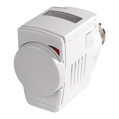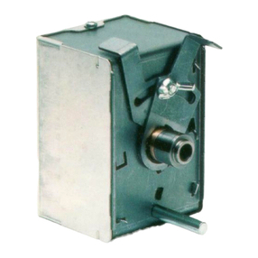
ML7284 NON-SPRING RETURN DIRECT COUPLED DAMPER ACTUATOR
63-2504—2 8
IMPORTANT
The ML7284 can operate with a DDC controller.Do
not short cycle the actuator. Short cycling of the
actuator can cause premature failure.
The actuator has a position indicator to show shaft position.
As the indicator moves with the shaft, it gives an angular
representation of the damper position.There are two distinct
positions where the indicator can be placed.The indicator
can be removed (by first removing the output hub) and
turned to provide proper position indication.The indicator
can be indexed to show open or closed, using the detents
that are 90°apart. See Fig. 3.
The ML7284D and ML7284F models provide a time-out
function that removes power from the actuator submotor if the
actuator remains in the fully open or fully closed position for
longer than a nominal 5 minutes.This time-out function helps
to extend actuator life.
CHECKOUT
Perform the following checkout procedure for the ML7284
Direct Coupled Damper Actuator.
1Check the actuator position indicator and damper shaft
position to see that they agree.
2Apply 24 Vac to the black (T1) and red (T2) leads.
3Apply minimum control signal (0 Vdc, +2 Vdc, or 4 mA)
to the white (Input) lead with respect to the black (T1)
lead:
• If the reversing switch is in the direct position, the
actuator should drive the damper to the closed
(counterclockwise ) position.
• If the reversing switch is in the reverse position,
the actuator should drive the damper to the open
(clockwise ) position.
4Apply maximum control signal (+10 Vdc or 20 mA) to
the white (Input) lead with respect to the black (T1)
lead.
• If the reversing switch is in the direct position, the
actuator should drive the damper to the open
(clockwise ) position.
• If the reversing switch is in the reverse position,
the actuator should drive the damper to the
closed (counterclockwise ) position.
Helping You Control Your World
Home and Building Control
Honeywell Limited-Honeywell Limitée
155 Gordon Baker Road
North York, Ontario
M2H 2C9
63-2504—2 G. R. Rev. 4-96 Printed in U.S.A.
Home and Building Control
Honeywell Inc.
1985 Douglas Drive North
Golden Valley, MN 55422
TROUBLESHOOTING
If the actuator does not operate properly during the checkout,
perform the following troubleshooting steps. Perform these
steps before replacing the actuator.
1Check actuator label to verify proper power and control
signal requirements for the application.
2Check for presence of 24 Vac at the black (T1) and red
(T2) leads when the actuator should be operating. If the
voltage is not present or is low, check the power supply
and actuator connections.
3Check control signal voltage (or current) for proper
value and polarity at the actuator white (Input) and
black (T1) leads when the actuator should be driving. If
the signal is wrong, not present, or low, check the
controller.The positive (+) signal must go to the white
(Input) lead. If this signal point is negative, change the
control wiring.
4Make sure the feedback wire is not connected to
24 Vac.
5Change the reversing switch if the actuator does not
drive in the desired direction when a control signal is
applied and the wiring is correct.
6Remove power and fully depress and hold the
disengage button while trying to turn the damper shaft
clockwise and counterclockwise . If the
damper shaft turn freely throughout the 90°stroke and
the actuator is installed correctly, replace the actuator.
7If the damper shaft will not turn freely for the full 90°,
check for any binding and make sure the actuator is
loose on its mount bracket to prevent binding. If
necessary, adjust the mounting bracket to prevent
binding.
8If no binding is noticed in the actuator and damper
assembly, remove the actuator and turn the damper
shaft clockwise and counterclockwise . If the
damper does not turn freely, fix or replace the damper.
9If the damper turns, fully depress and hold the
disengage button and turn the actuator hub clockwise
and counterclockwise . If the actuator does not
turn, replace the actuator.
JIf the actuator and damper turn freely, remount the
actuator to the damper following the instructions in the
Installation section. Make sure the actuator does not
bind, and that the damper and actuator are at the same
clockwise or counterclockwise end stop
when they are assembled. Connect all power and
control wiring and repeat the checkout.Troubleshoot if
necessary.
