Honeywell Versaguard TG509 User manual

PRODUCT DATA
® U.S. Registered Trademark
Copyright © 1996 Honeywell Inc. • All Rights Reserved
TG509, TG510, TG511, TG512 Versaguard™
Universal Thermostat Guards
GENERAL
The Versaguard™ Universal Thermostat Guards cover wall
thermostats and protect against tampering, damage and
unauthorized adjustment of thermostat settings.
FEATURES
❥Available in four sizes: mini, small, medium and large,
to fit virtually all thermostats.
❥Used in both new and existing applications.
❥Constructed of smoke-colored transparent
polycarbonate, off-white opaque polycarbonate,
opaque plastic, clear plastic or off-white painted steel.
❥Opaque plastic guards match commercial interior
decorating schemes.
❥Can be mounted on the wall or an exposed junction box.
❥Smoke-colored transparent or off-white opaque
polycarbonate ring base without wallplate, or opaque
plastic wallplate and plastic ring base. All models
include a guard cover, tumbler lock, two keys and a
Honeywell logo insert.
❥TG509F,G models permit thermostat calibration
without ring base removal.
❥Provision for Honeywell logo (included with all models)
or OEM logo on guard cover.
❥Ideal for office areas, lobbies, supermarkets,
restaurants, clinics, hospitals, convenience stores,
and similar applications.
❥Tamper-resistant lock; key can be removed only when
in the locked position.
❥Vertical or horizontal mount.
❥Guard base vents allow airflow for optimum
thermostat performance.
CONTENTS
General ............................................................................... 1
Features .............................................................................. 1
Specifications ...................................................................... 2
Ordering Information ........................................................... 2
Installation ........................................................................... 6
Checkout ............................................................................. 11
TG509 TG510A
TG511D TG512B
68-0104-4

TG509, TG510, TG511, TG512 VERSAGUARD™ UNIVERSAL THERMOSTAT GUARDS
68-0104—4 2
SPECIFICATIONS
IMPORTANT
The specifications listed in this publication do not
include normal manufacturing tolerances. Therefore,
this unit may not exactly match the listed specifications.
Also, this product is tested and calibrated under closely
controlled conditions, and some minor differences in
performance can be expected if those conditions are
changed. For exact engineering specifications, contact
your Honeywell representative.
TRADELINE® Models:
TRADELINE® models are selected and packaged for ease of
stocking, ease of handling, and maximum replacement value.
TRADELINE® Models Available:
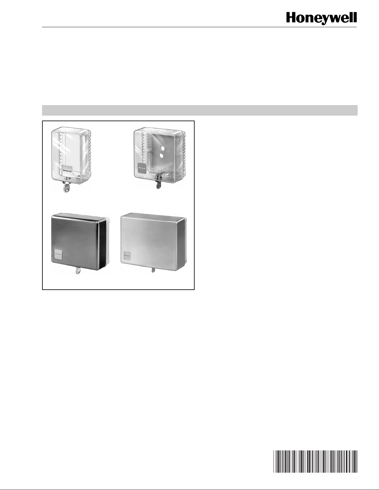
TG509F Versaguard™ Universal Thermostat Guard:
transparent polycarbonate cover (smoke tint) ring base
and allen wrench.
TG509G Versaguard™ Universal Thermostat Guard:
opaque polycarbonate cover (off-white) ring base and
allen wrench.
ORDERING INFORMATION
When purchasing replacement and modernization products from your TRADELINE® wholesaler or your distributor, refer to the
TRADELINE® Catalog or price sheets for complete ordering number, or specify:
1. Order number.
2. Transparent (smoke tint) or opaque (off-white) polycarbonate (TG509 models only), clear or opaque plastic, or painted
steel cover (off-white).
3. Accessory.
If you have additional questions, need further information, or would like to comment on our products or services, please write or phone:
1. Your local Honeywell Home and Building Control Sales Office (check white pages of phone directory).
2. Home and Building Control Customer Relations
Honeywell, 1885 Douglas Drive North
Minneapolis, Minnesota 55422-4386
In Canada—Honeywell Limited/Honeywell Limitee, 35 Dynamic Drive, Scarborough, Ontario M1V 4Z9. International Sales and
Service Offices in all principal cities of the world. Manufacturing in Australia, Canada, Finland, France, Germany, Japan, Mexico,
Netherlands, Spain, Taiwan, United Kingdom, U.S.A.
TG510A, TG511A, TG512A Versaguard™ Universal
Thermostat Guards: clear plastic cover, opaque plastic
wallplate and clear plastic ring mounting base.
TG510B, TG511B, TG512B Versaguard™ Universal
Thermostat Guards: opaque plastic cover, opaque plastic
wallplate and opaque plastic ring mounting base.
Standard Models:
TG510D, TG511D, TG512D Versaguard™ Universal
Thermostat Guards: painted steel cover (off-white), opaque
plastic wallplate and opaque plastic ring mounting base.
Additional Features:
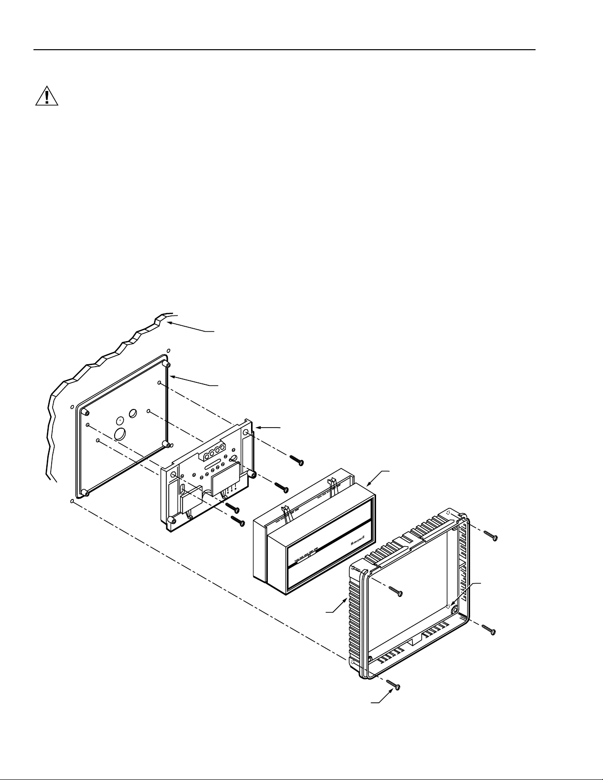
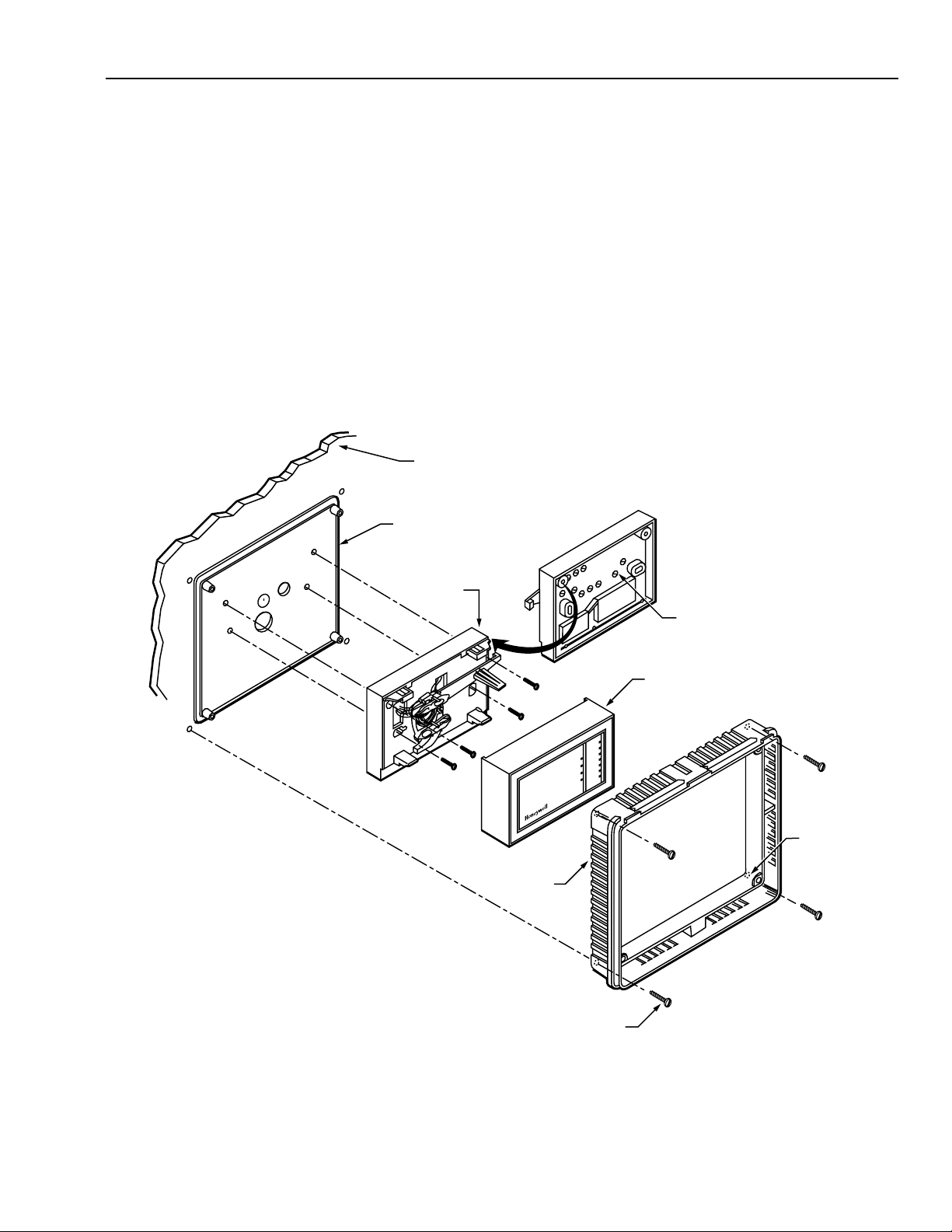
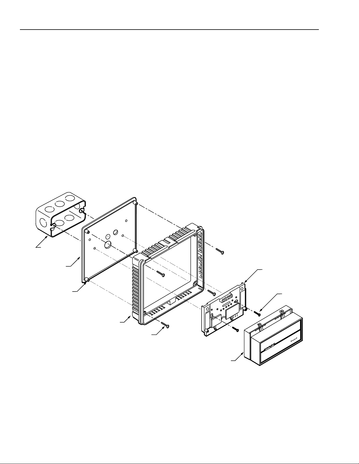
TRADELINE® and Standard Versaguard™ Universal
Thermostat Guards include Honeywell logo insert (field-
installed), mounting template, screws, anchors and tumbler
lock with two keys.
See Tables 1 and 2 for thermostat guard applications.
Accessory:
191990A Replacement Keys (2); can also be used with
TG500 and TG502 Thermostat Guards.

TG509, TG510, TG511, TG512 VERSAGUARD™ UNIVERSAL THERMOSTAT GUARDS
68-0104—4
3
Thermostat TG509 (Fig. 1)
HONEYWELL
TP970 ●
TP971 ●
TP972 ●
TP973 ●
TP974 ●
T7660 ●
TP9600 Series ●
JOHNSON
T4002 ●
T4100 ●
T4506 ●
T4756 ●
T5002 ●
POWERS
TH192 ●
TH193 ●
TH194 ●
TT184 ●
ROBERTSHAW
Original
T12 ●
T13 ●
T18 ●
T19 ●
T23 ●
T27 ●
T32 ●
T33 ●
T34 ●
T35 ●
Uniline
2211 ●
2212 ●
2214 ●
2216 ●
2218 ●
Table 1. TG509 Thermostat Guard Applications. Table 2.TG510,TG511,TG512
Thermostat Guard Applications.
Thermostat TG510
(Fig. 2) TG511
(Fig. 3) TG512
(Fig. 4)
HONEYWELL
T87/Q539 ●
a
●
c
T451 ●
T498 ●
T631 ●
T641 ●
T651 ●
T694 ●
T810 ●
T822 ●
b
T834 ●
b
T841 ●
T874/Q674 ●
a
T4039 ●
T6051A ●
T6052 ●
T7047 ●
T8034 ●
T42 ●
T92 ●
T921 ●
T7200 ●
T7300/Q7300 ●
T7400 ●
T8082/Q682 ●
T8085/Q682 ●
T8090/Q682 ●
T8195/Q682 ●
T8600 ●
T8601 ●
T8602 ●
T8603 ●
T8611 ●
T8621 ●
T8624 ●
T8631 ●
TP970 ●
W884 ●
Y594 ●

TG509, TG510, TG511, TG512 VERSAGUARD™ UNIVERSAL THERMOSTAT GUARDS
68-0104—4 4
aUse TG512 for thermostat wallplate with dealer logo.
bTurn TG511 90 degrees to fit thermostat wallplate with
dealer logo.
cFits T87F The Round® Thermostat with decorator wallplate.
Table 2.TG510, TG511,TG512
Thermostat Guard Applications
(Continued)
.
Thermostat TG510
(Fig. 2) TG511
(Fig. 3) TG512
(Fig. 4)
ITT GENERAL
T199 ●
T80 ●
T90 ●
T91 ●
T330 SERIES ●
T340 SERIES ●
ENERSTAT
DSP100—DSP700 ●
ET52 ●
HC-7 ●
HP-1 ●
K3-WN ●
K4-W ●
MS-1N ●
HP-2 ●
ROBERTSHAW
TX400 ●
500 SERIES ●
300-610 ●
300-620 ●
300-630 ●
300-642 ●
WHITE RODGERS
1C-30 ●
1C-31 ●
1C-70 ●
1D-30 ●
1D-35 ●
1D-36 ●
1E-30 ●
1E-31 ●
1E-35 ●
1E-36 ●
1E-56 ●
1F-30 ●
1F-56 ●
1F-57 ●
1F-58 ●
1F-60 ●
1F-62 ●
1F-70 ●
Table 2. TG510,TG511, TG512
Thermostat Guard Applications
(Continued)
.
Thermostat TG510
(Fig. 2) TG511
(Fig. 3) TG512
(Fig. 4)
WHITE RODGERS
1F-72 ●
1F-75 ●
1F-76 ●
1F-90 ●
1F-91 ●
1F-92 ●
1F-93 ●
1F-94 ●
1F-95 ●
1F-97 ●
AMERICAN STABILIS
R-90 ●
R-100 ●
R-105 ●
R-106 ●
HP-1 ●
HP-10 ●
HP15/20/22 ●
HP100 ●
HP150/200/220 ●
HP1000 ●
HP1500/2000/3000 ●
HP2001 ●
SIMPLESTAT ●
COLUMBUS ELECTRIC
RSH-420A ●
RSV-420 ●
HPC SERIES ●
SECO
TA-2000 ●
TM-1000 ●
TM-1400 ●

TG509, TG510, TG511, TG512 VERSAGUARD™ UNIVERSAL THERMOSTAT GUARDS
68-0104—4
5
Fig. 1. TG509 overall dimensions.
M15015
FRONT VIEW SIDE VIEW
G
E
F
TG510A 2-1/2 64 4-5/8 117 3-5/8 92 5-1/2 140 2-1/8 54
MODEL
NUMBER IN. IN. IN. IN. IN.MM MM MM MM MM
AFG
RING BASE ONLY
A
D
C
B
2-7/8 73
IN. MM
4102
IN. MM
CBDE
M642C
FRONT VIEW SIDE VIEW
G
E
F
TG510A
TG510B
TG510D
4-7/16
4-7/16
4-7/16
113
113
113
4-7/16
4-7/16
4-7/16
113
113
113
5-7/8
5-7/8
5-11/16
149
149
144
5-7/8
5-7/8
5-11/16
149
149
144
2-1/2
2-1/2
2-7/16
64
64
62
MODEL
NUMBER IN. IN. IN.. IN. IN.MM MM MM MM MM
AFG
RING BASE ONLY
A
D
B
C
3-1/2
3-1/2
3-1/2
89
89
89
IN. MM
3-1/2
3-1/2
3-1/2
89
89
89
IN. MM
CBDE
Fig. 2. TG510 overall dimensions.
TG511A
TG511B
TG511D
6-1/16
6-1/16
6-1/16
154
154
154
5-1/16
5-1/16
5-1/16
129
129
129
7-1/2
7-1/2
7-3/8
191
191
187
6-1/2
6-1/2
6-3/8
165
165
162
2-15/16
2-15/16
2-7/8
75
75
73
MODEL
NUMBER IN. IN. IN. IN. IN.MM MM MM MM MM
EADFG
M643C
FRONT VIEW SIDE VIEW
G
E
F
RING BASE ONLY
A
D
5-1/8
5-1/8
5-1/8
130
130
130
IN. MM
B
4-1/8
4-1/8
4-1/8
105
105
105
IN. MM
C
C
B
Fig. 3. TG511 overall dimensions.

TG509, TG510, TG511, TG512 VERSAGUARD™ UNIVERSAL THERMOSTAT GUARDS
68-0104—4 6
Fig. 4. TG512 overall dimensions.
E
F
TG512A
TG512B
TG512D
8-3/8
8-3/8
8-3/8
213
213
213
5-7/8
5-7/8
5-7/8
149
149
149
9-3/4
9-3/4
9-5/8
248
248
244
7-1/4
7-1/4
7-1/8
184
184
180
3-3/8
3-3/8
3-1/4
86
86
83
MODEL
NUMBER IN. IN. IN. IN. IN.MM MM MM MM MM
E
ADFG
M644C
FRONT VIEW SIDE VIEW
G
A
D
RING BASE ONLY
B
C
7-3/8
7-3/8
7-3/8
187
187
187
4-7/8
4-7/8
4-7/8
124
124
124
IN. IN.
MM MM
CB
INSTALLATION
When Installing this Product…
1. Read these instructions carefully. Failure to follow them
could damage the product.
2. Check the dimensions given in the instructions and on
the product to make sure the product is suitable for your
application.
The Versaguard™ Universal Thermostat Guards can be used
in new or existing thermostat applications. In existing
thermostat applications, the guard can be installed without
removing the thermostat from the wall. In these applications,
the thermostat guard is used without the solid wallplate (only
ring base and cover are used). In new thermostat
applications, the guard can be used with or without the solid
wallplate. The wallplate is typically used to cover mounting
marks from the old thermostat.
Refer to the following sections for specific mounting
procedures for thermostat guard applications.
Mount Thermostat Guard Without Wallplate
(Fig. 5 and 6)
쐃Place the ring base over the thermostat (and wallplate,
subbase or adaptor plate) on the wall.
쐇Align the ring base with the thermostat and level
approximately.
쐋Mark the four mounting holes.
NOTE: Do not use the four brass screws for mounting
the TG509. The brass screws are intended for
models with wallplates only.
쐏Mount the ring base on the wall using the four no. 6
sheet metal screws and four anchors provided as
shown in Fig. 5 for the TG509 and Fig. 6 for the FG510,
TG511 and TG512.
쐄Mount the guard cover by placing the hinged edge of
the guard cover on the ring base and swinging it down
(horizontal mounting) or to the side (vertical mounting)
until the guard cover is in place against the ring base.
See Fig. 7.
쐂Lock the thermostat guard by turning the key (provided)
counterclockwise. See Fig. 8. The key can be removed
only in the locked position.
쐆Remove the paper backing and clear protective cover
from the included monogram and place the monogram
in the recessed area on the guard cover. See Fig. 9.
NOTE: The TG509F,G Thermostat Versaguards™ are
shipped with an allen wrench secured in the
top notch of the ring base. When thermostat
calibration is needed, remove the Versaguard
cover and use the wrench to remove the top
two allen screws in the thermostat cover. This
allows servicing of the thermostat while the
ring base is in place.
THERMOSTAT
WALL
RING BASE
MOUNTING
HOLES (4)
MOUNTING SCREWS (4)
6
0
60
70
80
90
60
70
80
90
RING
BASE
KEY
M15014
RECESSED AREA
FOR MONOGRAM
COVER
FRONT OF DEVICE
MOUNTING RING BASE
Fig. 5. MountTG509 ring base only in existing thermostat
applications.TG509 guard cover, lock, monogram area.

TG509, TG510, TG511, TG512 VERSAGUARD™ UNIVERSAL THERMOSTAT GUARDS
68-0104—4
7
Fig. 6. Mount TG510,TG511 and TG512 ring bases only in
existing thermostat applications.
50607080
50 60 70 80
506070 80
HEATCOOL
THERMOSTAT
M653B
WALL
RING BASE
MOUNTING
HOLES (4)
MOUNTING SCREWS (4)
RING BASE
COVER
M654A
Fig. 7. Mount guard cover (TG510,TG511,TG512 shown).
Fig. 8. Lock thermostat guard
(TG510,TG511,TG512 shown).
RING BASE
KEY
M655
COVER
REMOVE
PAPER
BACKING
REMOVE
CLEAR
PROTECTIVE
COVER
MONOGRAM
1 TURN MONOGRAM 90 DEGREES
ON VERTICALLY MOUNTED GUARDS.
1
M656A
PLACE MONOGRAM
IN RECESSED AREA
ON GUARD COVER
Fig. 9. Apply monogram to thermostat guard
(TG510,TG511,TG512 shown).

TG509, TG510, TG511, TG512 VERSAGUARD™ UNIVERSAL THERMOSTAT GUARDS
68-0104—4 8
Mount Thermostat Guard With Wallplate
CAUTION
Disconnect power supply to prevent electrical shock or
equipment damage.
Wall Mounting Front-wired Subbase (Fig. 10)
쐃Place the thermostat subbase (or wallplate) on the
wallplate template and mark the mounting holes.
쐇Locate the mounting holes on the guard wallplate using
the template as a guide.
쐋Drill the required 5/32 in. mounting holes in the guard
wallplate.
NOTE: If the mounting hole pattern on the guard
wallplate does not match the pattern on the
thermostat subbase or wallplate, drill
additional mounting holes in the guard
wallplate.
쐏Mount the thermostat subbase (or wallplate) and the
guard wallplate to the wall using the 1-1/4 in. sheet
metal screws provided with the thermostat. The guard
wallplate must be placed between the thermostat
subbase (or wallplate) and the wall. See Fig. 10.
쐄Wire the thermostat subbase (or wallplate). Refer to the
installation instructions provided with the thermostat.
쐂Mount the thermostat on the subbase (or wallplate) and
place the thermostat cover on the thermostat.
쐆Mount the guard ring base over the thermostat,
subbase (wallplate) and guard wallplate.
쐊Attach the ring base using four no. 6 sheet metal
screws or four anchors and screws (provided).
쐎Mount the guard cover by placing the hinged edge of
the guard cover on the ring base and swinging it down
(horizontal mounting) or to the side (vertical mounting)
until the thermostat guard is in place against the ring
base. See Fig. 7.
쐅Lock the thermostat guard by turning the key (provided)
counterclockwise. See Fig. 8. The key can be removed
only in the locked position.
쐈Remove the paper backing and clear protective cover
from the included monogram and place the monogram
in the recessed area on the guard cover. See Fig. 9.
50607080
50607080
50607080
HEATCOOL
GUARD WALLPLATE
THERMOSTAT
M657B
SUBBASE
WALL
RING BASE
MOUNTING
HOLES (4)
MOUNTING SCREWS (4)
Fig. 10. Mount guard wallplate and ring base on thermostat with front-wired subbase or wallplate.

TG509, TG510, TG511, TG512 VERSAGUARD™ UNIVERSAL THERMOSTAT GUARDS
68-0104—4
9
Back-wired Thermostat (Fig. 11)
쐃Place the thermostat on the wallplate template and
mark the mounting holes.
쐇Locate the mounting holes on the guard wallplate using
the template as a guide.
쐋Drill the required 5/32 in. mounting holes in the guard
wallplate.
NOTE: If the mounting hole pattern on the guard
wallplate does not match the pattern on the
thermostat, drill additional mounting holes in
the guard wallplate.
쐏Mount the smooth side of the guard wallplate facing the
thermostat and run the system wires through the wiring
hole in the guard wallplate. The guard wallplate must be
placed between the thermostat and the wall. See Fig. 11.
쐄Back-wire the thermostat. Refer to the instructions
provided with the thermostat.
쐂Mount the thermostat and the guard wallplate to the
wall using the 1-1/4 in. sheet metal screws provided
with the thermostat. Make sure the guard wallplate is
placed between the thermostat and the wall.
쐆Place the thermostat cover on the thermostat.
쐊Mount the guard ring base over the thermostat and the
guard wallplate.
쐎Attach the ring base using four 1-1/4 in. sheet metal
screws or four anchors and screws (provided).
쐅Mount the guard cover by placing the hinged edge of
the guard cover on the ring base and swinging it down
(horizontal mounting) or to the side (vertical mounting)
until the guard cover snaps into place against the ring
base. See Fig. 7.
쐈Lock the thermostat guard by turning the key (provided)
counterclockwise. See Fig. 8. The key can be removed
only in the locked position.
쐉Remove the paper backing and clear protective cover
from the included monogram and place the monogram
in the recessed area on the guard cover. See Fig. 9.
GUARD WALLPLATE
THERMOSTAT
BASE
THERMOSTAT COVER
M658A
80
70
60
50
WARM
COOL
CONNECT WIRES
TO TERMINALS ON
BACK OF THERMOSTAT BASE
WALL
RING BASE
MOUNTING
HOLES (4)
MOUNTING SCREWS (4)
Fig. 11. Mount guard wallplate and ring base on back-wired thermostat.

TG509, TG510, TG511, TG512 VERSAGUARD™ UNIVERSAL THERMOSTAT GUARDS
68-0104—4 10
Junction Box Mounting (Fig. 12)
쐃Place the thermostat subbase (or wallplate) on the
wallplate template and mark the mounting holes.
쐇Locate the mounting holes on the guard wallplate using
the template as a guide.
쐋Drill the required 5/32 in. mounting holes in the guard
wallplate.
쐏Secure the guard wallplate to the ring base using the
screws provided.
쐄Place the guard wallplate (with smooth side facing the
ring base) on the back of the ring base.
쐂Insert the securing screws through the holes on the
front of the ring base and into the posts on the
wallplate. See Fig. 12.
쐆Tighten the screws securely.
NOTES: When using a front-wired subbase
(wallplate), run the system wires from the
junction box through the wiring hole in the
guard wallplate and subbase (wallplate)
cable opening.
When using a back-wired subbase
(wallplate), run the system wires from the
junction box through the wiring hole in the
guard wallplate only.
쐊Wire the back-wired subbase. Refer to the instructions
provided with the thermostat.
쐎Mount the thermostat subbase (wallplate) and the ring
base with the guard wallplate to the junction box using
the 1-1/4 in. sheet metal screws provided.
쐅Wire the front-wired subbase (wallplate). Refer to the
instructions provided with the thermostat.
쐈Mount the thermostat on the subbase (wallplate).
쐉Place the thermostat cover on the thermostat.
씈Mount the guard cover by placing the hinged edge of
the guard cover on the ring base and swinging it down
(horizontal mounting) or to the side (vertical mounting)
until the guard cover is in place against the ring base.
See Fig. 7.
씉Lock the thermostat guard by turning the key (provided)
counterclockwise. See Fig. 8. The key can only be
removed in the locked position.
씊Remove the paper backing and clear protective cover
from the included monogram and place the monogram
in the recessed area on the guard cover. See Fig. 9.
THERMOSTAT
M1638A
GUARD
WALLPLATE
HORIZONTAL
OUTLET BOX
50 60 70 80
50 60 70 80
50 60 70 80
HEAT COOL
MOUNTING
SCREWS (2)
SUBBASE
SECURING SCREWS (4)
RING BASE
WALLPLATE
POSTS
Fig. 12. Mount guard wallplate with ring base and thermostat on junction box (front-wired thermostat subbase shown).

TG509, TG510, TG511, TG512 VERSAGUARD™ UNIVERSAL THERMOSTAT GUARDS
68-0104—4
11
Remove Thermostat Guard
쐃Remove the thermostat guard cover by inserting the
key and turning the key clockwise until the locking
mechanism is disengaged.
쐇Remove the guard cover by swinging it out away from
the ring base and lifting it off. See Fig. 13.
CHECKOUT
Before leaving the installation, refer to the applicable
instructions to check the operation of the thermostat or
subbase.
COVER
RING BASE
M659
KEY
Fig. 13. Remove thermostat guard cover
(TG510,TG511,TG512 shown).

TG509, TG510, TG511, TG512 VERSAGUARD™ UNIVERSAL THERMOSTAT GUARDS
68-0104—4 12
Honeywell Europe S.A.
3 Avenue du Bourget
B-1140 Brussels Belgium
Honeywell Asia Pacific Inc.
Room 3213-3225
Sun Hung Kai Centre
No. 30 Harbour Road
Wanchai
Hong Kong
Home and Building Control
Honeywell Limited-Honeywell Limitée
155 Gordon Baker Road
North York, Ontario
M2H 2C9
Honeywell Latin American Division
Miami Lakes Headquarters
14505 Commerce Way Suite 500
Miami Lakes FL 33016
Helping You Control Your World®
68-0104—4 J.S. Rev. 11-96 Printed in U.S.A.
Home and Building Control
Honeywell Inc.
Honeywell Plaza
P.O. Box 524
Minneapolis MN 55408-0524
Printed on recycled paper containing at
least 10% post-consumer paper fibers. www.honeywell.com/yourhome
This manual suits for next models
3
Table of contents
Other Honeywell Enclosure manuals

Honeywell
Honeywell HPB407 Technical manual

Honeywell
Honeywell Fire-lite ROME Series Technical manual

Honeywell
Honeywell PRO-2200 User manual

Honeywell
Honeywell HHC12 Series User manual

Honeywell
Honeywell PRO22ENC2 User manual

Honeywell
Honeywell 51404897-501 User manual

Honeywell
Honeywell NetAXS-123 Installation guide
Popular Enclosure manuals by other brands

Waterway
Waterway 640-472 V Series owner's manual

Vectronics
Vectronics VEC-1300KC Assembly manual

Safe-t-Cover
Safe-t-Cover 200D Series Assembly instructions

ACO
ACO UNIFACE GS Assist installation manual

Teledyne
Teledyne Everywhereyoulook ENC-560 installation guide

Strand
Strand Vision.Net 53906-001 quick start guide