Honeywell KFC 150 Manual

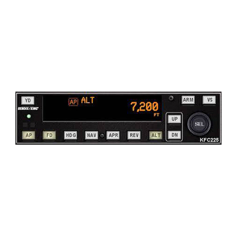
PILOT’S GUIDE FOR THE
KFC ISO/KAP
150
&
KAP
100
FLIGHT CONTROL SYSTEMS
I__-

CONTENTS
Introduction
.......................................................................
3
.....
4
System Integration
..................................
6
.....
7
GeneralDescription: KFC 150, KAP 150and KAP
100
Silver Crown Panel-MountedFlight ControlSystem Capabilities
....
5
TypicalKFC 150FlightControlSystem (Diagram)
...........
TypicalKAP 150Autopilot System (Diagram)
......
.....
8
TypicalKAP 100Autopilot System (Diagram)
......
.....
9
..........
...........
.10
...........
.io
KC 190..
...
...........
.io
...........
.ll
KG258
.... .......
.I1
KI254
.....
.......
.I1
KG 253
........
.......
.I1
KI204/206
...... .......
.I2
...........
.I2
...........
.I2
KA185
................ ...........
.12
KAS
2978
.............
...........
.I2
System MonitorDescription
....
...........
.I2
KFC
150
Flight ControlSystem
............. .......
.13
Modesof Operation
...................... ....
.14-15
InitialPower On
..............
...........
.I6
System SelfTest.
....................
Attitude ReferenceMode
of
Operation
Operatingthe KFC 150System
....
FlightDirectorMode
Autopilot Engageme
.......................
20
Approach Mode(APR)
................
.......................
21
Back CourseMode(BC)
...........
...................
22
Altitude HoldMode(ALT)
...................
22
Auto/ManualTrim
....................
.......
23
ControlWheel SteeringMode (CWS)
.....
.......................
23
TakeoffandClimbto AssignedAltitude
....
.24-25
VOR/RNAVCapture
..........
...
....
.30-31
The
KAP
150
Autopilot System
.............
.......
.33
Modesof Operation
............
....
.34-35
System SelfTest
.................. ...................
...........
.36
Attitude Referenc of Operation
.
...........
..
37
Autopilot Mode (AP)
...........................
.......
..
37
HeadingSelectMode(HDG)
.................................
..
38
(NAV,
VOR,
RNAV)
..................................
39
(NAV, VOR, RNAV)
...................
Approach ModeUsingthe KG 107/KI206 In
Back Course ModeUsingthe KG 107/KI206 Indicators(BC)
..........................
44
Back Course ModeUsingthe OptionalKI525A PNI(BC)
.....................
45
Altitude HoldMode (ALT)
...
....
46
Auto/ManualTrim
......
...
....
...........
.47
ControlWheel SteeringMode (CWS)
.
47
Take
off
andClimbto AssignedAltitude
....
.48-49
ILS
Approach (KG 107/KI206)
...................................................
.50-51
KFC 150OperatingProcedures
Outboundon FrontCoursefor Procedu
FrontCourse
ILS
Approach
...........................
LongRangeNAVTracking
....................
32
InitialPower On
.....................
36
NavigationModeUsingthe KG 107/KI206 Indicators
NavigationMode Usingthe OptionalKI525A PNI
Approach Mode Usingthe OptionalKI525A PNI (APR)
.............................
...............................
40
.........................
KAP 150OperatingProcedures
Outboundon FrontCoursefor ProcedureTurn to
...
...
...
...................
...................
...................
...................
...............
...............
....
....
....
............
............
...........
............
........
........
...............
...............
...........
...........
...........
...........
1

Outboundon FrontCoursefor ProcedureTurn to ILSApproach (KI 525A)
...................
52-53
FrontCourse ILSApproach (KG 107/KI206)
.........................................
54-55
FrontCourse ILSApproach (KI525A)
..............................................
56-57
RNAV Capture(KG 107/KI206)
.............. ........................
58-59
RNAV Capture (KI 525A)
................... .......................
.60.61
LongRangeNAV Tracking
...... .... .... ...........
62
...........
...........
....
...
The KAP
100
AutopilotSystem
...
Modesof Operation
...........
Operatingthe KAP
100
System
System Self-Test
................
Attitude ReferenceModeof Operation
....
Autopilot Mode(AP)
..................
HeadingSelectMode(HDG)
NavigationModeUsingthe
KG
107/KI206
NavigationModeUsingthe OptionalKI525A PNI
ApproachMode Usingthe KG 107/KI206 Indicator(APR)
........
ApproachMode Usingthe OptionalKI525A PNI (APR)
..........
Back CourseMode Usingthe KG 107/KI206 Indicators(BC)
......
ManualElectricTrim
......................
..
Indicators(NAV) (VOR. RNAV)
...................
(NAV) (VOR. RNAV)
...............................
Back CourseMode Usingthe OptionalKI525A P
ControlWheel SteeringMode(CWS)
.........
......
..
KAP 100Operating Procedures
Outbound on FrontCoursefor Proc
ILSApproach (KG 107/KI206)
Outbound on FrontCoursefor Proc
FrontCourse ILSApproach (KG 107/KI206)
RNAV Capture(KG 107/KI206)
.....................
RNAV Capture(KI 525A)
LongRangeNAV Tracking
............................
Optional KAS
2978
Altitude and Vertical Speed Selector
.....
AltitudePreselect
...............................
AltitudeAlerting
..................
Vertical Speed Preselect
......................
Vertical Speed Synch
.........................
Test Mode
.................................
ILS
Approach (KI525A)
.....
FrontCourse ILSApproach (KI 525A)
.....
KAS
2978 OperatingProcedure
KCS55A CompassSystem
.....................
Altitude Profile
..........................
KI
525A Indicator
................................
Descriptionof Indicatorand Display Functions
..........
Slaving Meter
...................................
KMTll2
.....................................
KG102A
...............
....
Operating Instructions
..... ....
KCS55A Fliaht Procedures
.......
..
..
...
.........
.....
...
...
.......
63
....
.64.65
....
66
.......
67
.......
67
....
68
.......
69
....
....
70
...................
71
...................
72
......................
73
......................
74
...................
75
...................
75
.......
..............
.............
.......
....
.76.77
....
.7
8.79
....
.8
0.81
....
32-83
....
34-85
.....
86.87
.......
88
.......
89
.......
90
.......
90
.......
91
.......
91
.......
91
....
.92.93
.......
95
.......
96
....
.97.98
.......
99
......100
..........
100
.......
101-102
..........
103
Vectors tolntercept a Radial
.......
Turn to InterceptVictor Airway
....
Airway Interception
.................
HoldingPattern
...................
ILSApproach Front Course
..........
ReverseLocalizer Approach (BC)
......
GeneralEmergencyProcedures
Optional NAV I/NAV
2
Switching
.......
SystemWeight and Power Requirements
BendidKingWarrantyService
.........
......
......
.......
.......
.......
...................................
104
................................
105-106
107
...................................
108
.......................
......
109
110
........ ......
111
................................
113
................................
115
....
.......
.BackCover
2

INTRODUCTION
The pressuresof single-pilotinstru-
mentflying place criticaldemands on the
skill and concentration of any pilot.
To helpyou meetthe challenge, King
Radio has developedthree digital,panel-
mountedSilver Crown flight control systems
for single and twin engine aircraft.
These systems bring digitalflight con-
trol technology from the flightdeck of the
new generation airlinersto the cockpitsof
piston poweredaircraft for the first time.
The result is lightweight, compactflight con-
trol systems which incorporatethefunctions
of computer, mode selector, and annuncia-
tor in a single, panel-mountedunit. These
digitalpanel-mounted systemsuse fewer
partsthan previous generation flightcontrol
systems for singles and twins. And fewer
partsmean potentially greater reliability.
It's also significantthat these Silver
Crownflight control systems have been
designedfrom the beginningto interface
with your Silver Crown packageof
'
COMM/NAV Pulseproducts. Consider the
advantage of having your avionics working
together as an integratedsystem rather
than as a group of unrelated components
builtby several manufacturers.
To fully utilizethe impressivecapabili-
ties of your new digital, panel-mounted
flight control system, you must understand
the performance capabilitiesand basic
operational requirementsof these
advanced-designSilver Crown systems.
This pilot'sguide is divided intothree sec-
tions. The first providesa general familiar-
izationwith eachflight control system
includingthe associatedpanel-mounted
displays. The secondsection describes
each system, includingthe KCS
55A
slaved
compasssystem and its operation, as well
as optionalaltitude preselect/alertingand
verticalspeed hold. The final section cov-
ers emergency proceduresand optional
NAV 1/NAV
2
switching.
3

GENERAL DESCRIPTION:
KFC
150,
KAP
150
AND KAP
100
--
KFC 150Flight ControlSystem
The KFC 150 is the ultimatepanel-
mounted digitalflight control system for sin-
gles and twins. It has the autopilot capabili-
ty you need, plus a complete flightdirector
system. The flight director provides attitude
commandsfor the pilotto hand-fly, or dis-
playsto the pilotthe commands beingfol-
lowed bythe autopilot. The KFC 150 has
capabilitiessimilar to King'spopular KFC
200
FlightControl System.
UP150AutotMot Svstem
The
MP
150Autopilot System is a
two-axis,panel-mounted digitalsystem
which delivers highly sophisticatedIFR
capability. It has modes and functions simi-
lar to the KFC 150 but has no flight director.
KAP 100Autopilot System
The
KAP
100
Autopilot System is a
single-axis panel-mounteddigitalsystem
which extends Silver Crown quality and reli-
ability
to
an entirely new entry-level capabil-
ity. The
KAP
100Autopilot is the most
affordable option in the Silver Crown line
of
flight control systems and offers many sub-
stantial workload relief benefits.
The followingchart highlightsthe major
attributesof each of thethree systems
4

B
0
D
D
B
D
D
D
B
D
D
B
B
B
P
B
B
B
B
D
B
B
D
D
B
D
D
B
D
B
B
B
D
B
D
SILVER CROWN PANEL-MOUNTED
FLIGHT CONTROL SYSTEM CAPABILITIES
Two Axis
SingleAxis
Flight Director
KI
525A
PNI
KG 107 DG
KG
258
HorizonReference
Indicator
KI
256
FlightCommand
Indicator
Automatic Electric
ElevatorTrim
ManualElectricTrim
Yaw Damper
KA 185 Remote
ModeAnnunciator
KAS2978Altitude Preselect/
Alerting, Vertical SpeedHold
FUNCTIONS/MODES
ALT Hold(ALT)
ALT Preselect
HeadingSelect(HDG)
NAV (VOR/RNAV)
Approach (APR)
Glideslope
(GS)
BackCourse(BC)
Control Wheel Steering(CWS)
Vertical Speed Hold
VerticalTrim
Auto Capture
AutoTrack
All Angle
Intercept
Auto 45-degree Intercept
TEST
ManualandAuto
Trim Monitor
Roll
Rate Monitor
PitchRateMonitor
KFC
150
Yes
Yes
Standard
-
-
-
Standard
Standard
Standard
Optionalfor
some aircraft
Optionalfor
some aircraft
Optionalfor
some aircraft
Yes
Optional
Yes
Yes
Yes
Yes
Yes
Standard
Optional
Yes
Yes
Yes
Yes
~
Both
Yes
Yes
KAP
150
Yes
-
-
Optional
Standard
Standard
Standard
Standard
Optionalfor
some aircraft
Optionalfor
some aircraft
Optionalfor
some aircraft
Yes
Optional
Yes
Yes
Yes
Yes
Yes
Standard
Optional
Yes
Yes
Yes
Optional(with
KI 525A)
Standard(with
KG 107)
Both
Yes
Yes
KAP
100
Yes
Optional
Standard
Standard
-
-
-
-
Optional
-
Optionalfor
some aircraft
-
-
Yes
Yes
Yes
-
Yes
Optionalwith
Kingmanual
electric trim
-
Yes
Yes
Optional(with
KI 525A)
Standard(with
KG 107)
ManualTrim Monitor
(with Kingmanual
electrictrim option)
Yes
NOTE: The KFC 150,KAP 150and KAP 100are designedas independent systems
to
maximizetheir indi-
vidual capabilities. Thereforethey are not designedfor conversionfrom one system
to
another.
IMPORTANT:
This Pilot'sguideprovidesa generaldescriptionof variousoperationalcharacteristicsof the
KFC 150, KAP
150
andKAP 100Flight ControlSystems. However,operationof a system shouldnot
be
attemptedwithout reviewingthe specificinformationinthe FAA approved Aircraft Flight ManualSupplement
for your particularaircrafttype.
5

SYSTEMS
INTEGRATION
The individualsystems diagrams on
pages
7,8,
and
9,
show the components
and their relationshipsin typical KFC
150,
UP
150
and KAP
100
Flight Control
Systems. The actual components used on
individual aircraft may vary slightly in order
to
optimize certificationand installation
requirements.
Each system has a number of inputs
and outputs: sensor outputs are shown in
red;computation inputs shown in blue; dis-
play outputs shown in orange; and aircraft
control shown in green. The systems dia-
grams reflectthat the KAP
150
and KFC
150
systems control both pitch and roll axes
of the aircraft. The KAP
100,
beinga sin-
gle-axis system, controls only the roll axis of
the aircraft.
All
sensor information(pitch
and roll reference,headingand course
datum, RNAV/VOR/LOC/GSdeviation and
flags, marker receiverand static pressure
[altitude]
is
fed into the system'sflight com-
puter).
The flight computer computespitch
and roll steering commands (or in the case
of the KAP
100,
roll commands only). In the
KFC
150
system these commands are rout-
ed through the KI
256
Flight Command
Indicator (FCI),where they are displayedon
the V-Bar as visual guidancecommands.
In all three systems these steering
commands are fed
to
the autopilot compu-
tation circuitscontained in the appropriate
flightcomputer which generates the com-
mands for the individualservos to manipu-
late the ailerons, elevator and elevator trim.
An optional yaw channel is available for
some aircraft, but is independentof pitch
and roll commands.
mands in the KFC
150
system for flight
director and autopilot provides totally con-
sistent flight director steering command and
autopilot control. There is no disagreement
in computation. The autopilot simply con-
verts the pitch and roll steering commands
from the flight computer, displayedon the
V-Bar inthe FCI, into the requiredelevator
and aileron position commands. Full inte-
gration of flightdirector and autopilot allows
the pilotto delegatethe manual effort of fly-
ingthe aircraft to the autopilot while moni-
toring its activitywith the flight director.
Usingthe same pitch and roll com-
6

TYPICAL KFC
150
FLIGHT CONTROLSYSTEM
VOWLOC/RNAV Static
1
Deviation Pressure
KA
185
MOL-
.
..inunciator
(Optionalon someaircraft). KC 192
Computer1
Glideslope
Deviation
PitchAltitude1
L
-
PitchCommand/
Roll
Command
KI256 Flight
CommandIndicator
K
I
NavigationIndicator
KMT112
KG 102A
Slaved DG
Detector
-
r"s
L
t
E
LI
Controller1
contains
computer
functions,
modecontrol
buttons, and
annunciator
lightsin a
singleunit.
Also contains
altitude
1
1
1
Annunciator
1
I
Autopilot Disconnect/
Trim Interrupt
OR
nM.J,n
KA51B
SlavingAccessory
Thisisa2-Axis(Pitchand
Roll)
System.
ThirdAxisYaw DamperSystem
(Optionalon someaircraft).
unted (May not beincluded
rol inallYaw Damper
installations)
T
KC 192Autopilot
ComputerKontroller
Annunciator
[I'
7

TYPICALKAP
150
AUTOPILOT SYSTEM
VOR/LOC/RNAV Static
Deviation Pressure KC
191
Computer/
Glideslope Middle
Devi?ion Marker Controller/
Annunciator
contains
computer
functions, mode
controlbuttons,
andannunciator
lightsina
singleunit.
Alsocontains
altitude
sensor.
PitchAttitude/
KG
238
Attituae
ReferenceIndicator
IIII
1111
HeadingSelect
&
CourseDatum
I
KG107 KI204 or otherCourse
I
I
DirectionalGyro DeviationIndicator
I
I
(not included).
II
I-
I
I
I
I
I
/
I
[rimInterrupt
t
KMT112
I
I-Y
d
I
I
Flux
I
KI525A Pictorial
I
NavigationIndicator
I
I
I
I
KCS55A Slaved
m
I
nR
AI
I
slaving
ACC~S!
........................
Thisisa 2-Axis (Pitchand
Roll)
System.
ThirdAxisYaw DamperSystem
(Optionalon some aircraft).
I
5L1”
norrfr
Panel-Mounted (May notbe included
Switch installations)
YD Annunciator
18
Yaw Control inallYaw Damper
T
I
KC
I
J
I
MUlU~llUl
ComputedController
Annunciator
r”
Roll
Crossfeed
Yaw Servo
KRG
331
RateGyro Yaw Computer
L

TYPICAL KAP
100
AUTOPILOT SYSTEM
KA
185
ModeAnnunciator
(Optionalonsome aircraft).
KG
258
Attitude
ReferenceIndicator
Middle VOWLOC/RNAV
KC
190
Computer/
Controller/
Annunciator
I
Roll
Attitude
HeadingSelect
&
Course Datum
I
I
I
I
I
I
I
I
I
I
I
I
I
KG
107
KI
204
or otherCourse
I
DirectionalGyro Deviation Indicator
I
(not included).
I
.....................
OR
.......................
-
KG 102A
I
1
+
L,
SlavedDG
I
I
I
I
II
-1
KMT112
I
I
NavigationIndicator
-
Detector
I
7
4
I
KI
3.cm
ricioriai Flux
I
I
I
IR
(7)
I
I
KCS55A Slaved
I
I
CompassSystem
I
(Optional)
KA
51A
a-51B
I
I
I
Slaving Accessory
I
contains
computer
functions, mode
controlbuttons,
and annunciator
lightsina
singleunit.
-D
KS 179
PitchTrim
Servo
Autopilot Disconnecff
Thisisa Single-Axis
(Roll)
System.
ManualElectric
I
Trim (Optional)
ControlWheel
Steering(Optional)
9

DESCRIPTION OF PANEL UNITS
KC 192 Mode
Controller/Computer/Annunciator
The KC 192 ModeController/
Computer/Annunciatorfor the KFC 150 sys-
tem incorporatesall computer functions,
mode control buttons and annunciator lights
in a single panel-mounted unit. The KC 192
annunciatesall verticaland lateralflight
director and autopilot system modes.
Inaddition,the KC 192 has seven push but-
tons for engagingflightdirector and/or
autopilot modes, a push buttonto initiate a
system self-test,and a verticaltrim rocker
switch to allowfor changingthe aircraft's
pitch up or down without disconnectingthe
autopilot.
T
R
I
hl
KC 191 Mode Controller/Computer/Annunciator
The KC 191 Mode Controller/
Computer/Annunciatorfor the KAP 150
incorporatesthe functions of a computer,
mode controller and annunciator lights in a
single, panel-mountedunit. The KC 191
annunciatesall verticaland lateralautopilot
system modes. Inaddition,the KC 191 has
six push buttons for engaging autopilot
modes, a push buttonto initiatesystem self-
test, and a verticaltrim rocker switch to
allow for changingthe aircraft pitch up or
down without disconnectingthe autopilot.
KC
190 Mode
Controller/Computer/Annunciator
The KC 190 ModeController/
Computer/Annunciatorfor the
KAP
100
incorporatesthe functions of a computer,
mode controller and annunciator lights in a
single, panel-mounted unit. The KC 190
annunciatesall lateralautopilot system
modes. In addition,the KC 190 has five but-
tons for engagingautopilot modes, and a
push buttonto initiate system self-test.
10

KI
256
FlightCommand indicator
(FCI)
information:
The KI 256 displaysthe following
Pitchand roll attitude.
Flight Director pitch and roll
commands.
DH (decisionheight) annunciation
when usedwith a radar altimeter.
The KI 256 contains an air-driven
vertical gyro. Engine(s) must be run-
ning, pressureor vacuum system oper-
ating and gyro up to speed beforethe
system will operate. Allow three min-
utesfor the gyro to come up to speed.
KG
258
HorizonReference Indicator
information:
The KG 258 displaysthe following
Pitchand roll attitude.
DH (decisionheight)annunciation
when usedwith a radar altimeter.
The KG 258 contains an air-driven
attitudereference indicator. Engine(s)
must be running beforethe system will
operate. Allow three minutesfor the
gyro to come up to speed.
KI
254
Electric Flight Command Indicator
(W
KG
253
ElectricHorizonReference
Indicator
information:
The KG 253 displaysthe following
Pitchand roll attitude.
DH (decisionheight) annunciation
when usedwith a radar altimeter.
The KG 253 is an electric attitude
referenceindicator. Electricalpower
(D.C.)
must be applied in order for the
unit to operate. Immediatelyfollowing
electricalpower turn-on,the knob
labeled"Pullto Erect"should be pulled
out with a moderate,even pull and
held in the
out
positionfor approxi-
mately three seconds. The knob
should then be releasedquickly but
smoothly. Erectingthe unit should only
by accomplishedwhile the aircraft is
relativelylevel on the ground or in level
flight. The gyro must be up to speed
beforethe systemwill operate. Allow
three minutesfor the gyro to come up
to speed.
The
KI
254 displaysthe following
Pitchand roll attitude.
Flight Director pitch and roll com-
mands.
DH (decisionheight)annunciation
when usedwith a radar altimeter.
The KG 254 contains an electric
vertical gyro. Electrical power (D.C.)
must beapplied in order for the unitto
operate. Immediatelyfollowing electri-
cal power turn-on,the knob labeled
"Pullto Erect"should be pulled out with
a moderate,even pull and held in the
out positionfor approximatelythree
seconds. The knob should then be
released quickly but smoothly.
Erectingthe unit should only be
accomplishedwhile the aircraft is rela-
tively levelon the ground or in level
flight. The gyro must be up to speed
before the systemwill operate. Allow
three minutesfor the gyro to come up
to speed.
information:
11

KI 204/206 KG 107
KA 185
KI204/206 Course DeviationIndicator
The KI 204/206 displays the following:
VOR/LOC/GLIDESLOPEDeviations.
CourseSelect (06s).
TO/FROM Flag Indication.
The KI 204/206 is usedwith the KN
53,
KX
155
or KX 1758,and the KN 75
Glideslope Receiver. The KI 206 is used
with the KN
74,
KNS 80, KNS
81,
KX
165or
KNC 610.
KG
107 Directional Gyro
The KG 107 DirectionalGyro displays
Unslavedgyro magnetic headinginfor-
Selected heading(HDG 'bug").
thefollowing information:
mation.
The KG 107 is an air-drivendirectional
gyro indicator. Engine(s)must be running,
pressureor vacuum system operatingand
gyro up to speed beforethe system will
operate. Allow three minutesfor the gyro to
come up to speed.
KI
525A HorizontalSituation Indicator
The
KI
525A is the displayportionof
(HSI)
the KCS 55A Slaved Compass System and
displays thefollowing:
Slavedgyro magnetic headinginforma-
Selected heading(HDG "bug").
VOR/LOC/RNAV course deviation.
Glideslopedeviation.
KA 185 ModeAnnunciator (Optional)
ciation displayof all appropriateoperating
tion.
The KA 185 provides a parallel annun-
KI 525A
KAS 297B
modes and may be positioned on the panel
in the pilot'snormal scan.
(Optional)
130A Altimeter to providealtitude prese-
lectlalertingand verticalspeed modes for
the KFC 150and
KAP
150systems.
System Monitor Description
Through the use of extensivemonitor
circuitsin the 100 seriesflight control sys-
tems, safer control of the aircraft is provid-
ed, sincefailures are predominantly
"soft"
(aircraftcontrol is automatically returnedto
the pilotwhen a fault is detected). Because
of this safety factor, the 100 seriesflight
control systems are ableto provide
smoother control of the aircraft due to
increased servo authority.
The internalmonitors continuously
check for the presenceof operatingpitch
and roll microprocessors,adapter modules
(usedto tailor the autopilot to individualair-
craft models), pitch and roll referencesig-
nals, proper internal voltages, trim power,
"runaway"auto trim, wrong directionof trim,
abnormal pitch attituderates, and abnormal
roll attitude rates.
The trip levels for pitch and roll attitude
rates and duration are independently set on
the adapter modulesfor each aircraft.
Digitaldesignallows the incorporation
of these monitorswithout the weight and
space penalties associated with previous
technology systems. Now these important
safety features are availableto the opera-
tors of pistonengine aircraft at a reasonable
price.
KAS
297B Altitude Selector
The KAS 2978 is usedwith a KEA
12

B
D
m
THE
KFC
150
FLIGHT CONTROL SYSTEM
The KFC
150
is the ultimatein digital The pilot can then manuallyfly the
commands shown on the
KI
256,
or engage
the autopilot portion of the system and have
it fly the commands. Monitoringthe single-
cue steering command (V-bar)will tell the
pilot if the commands are being satisfied.
A
0
panel-mountedflight control systems for
singles and twins.
The system incorporates a highly
capabletwo-axis autopilot and a flight
director system. An optional third-axis (yaw
0
)I
I,
damper) system is available for some air-
craftat a slightly higher cost.
er which calculatesthe appropriatepitch
and roll attitudes requiredto intercept and
maintainheadings, courses, approach
paths, pitchattitudes and altitudes. Once
computed,the commands are displayedto
the piloton the single-cue steering com-
mandwhich is part
of
the
KI
256
Flight
Command Indicator (FCI).
The flight director system is a comput-
good cross-check is to monitorthe raw data
(course or localizer and glideslope informa-
tion) on the KI 525A PNI to see
if
the aircraft
is interceptingor trackingcourse and glide-
pathas desired. (If you are unfamiliar with
the operation of a Pictorial Navigation
Indicator (PNI) you should stop here and
review the section of the KCS 55A Compass
Systemon page
95.)
13
B

Vertical Trim Glideslope (GS)
I
Trim Failure
Warning
I
Flight
/
Director (FD)
/
Altitude
Hold
(ALT)
Self-Test Autopilot
Engage
I'
(AP ENG)
(APR) (ILS,
VOR or RNAV)
/
.
.---ing
Back
Select (HDG)
/
Navigation
(NAV)
(VOR/RNAV) Course
(BC)
Electric
Trim Switch
Autopilbt
Disconnect/
Trim Interrupt
I
Ei:ISteeri(ng
(CWS)
Mode Flight DirectorlAutopilotAction
Attitude Reference Power on andno modesselected. FCIdisplays
aircraftattitudeand
PNI
displaysaircraftheading.
CommandV-bar isbiased
out
of view. Aircraft
engine@)mustberunningfor pressureor vacuum
to beappliedto FCIattitudegyro.
FlightDirector(FD) V-bar will appear andcommandwings level
andpitchattitude of the aircraftat the time of
modeselection.
Autopilot Engage (AP
ENG)
Aircraft control surfaces (aileronsand elevators)
smoothly respondto all selected Flight Director
modecommandswith automaticpitchtrim.
EngagesYaw Damper
if
present.
14

Mode
Flight Director/AutopilotAction
Heading(HDG) Selectdesiredheadingon PNI,then select
HDG mode. The V-bar will commandthe
necessary banktoturn to and maintainthe
selected heading.
Navigate(NAV)
(VOR/RNAV) The V-bar will commandthe bank necessary
toturnto and maintaina VOR or RNAV course
selected bythe pilot.
The V-bar will commandthe bank and pitch
necessaryto capture andtrack localizer and
glideslopefor ILSapproaches, or to captureand
trackthe appropriatecourse for VOR or RNAV.
The V-bar will commandthe banknecessary
to captureandtrack a reverselocalizer course.
Glideslopeis lockedout.
Approach (APR)
(ILS,VOR or RNAV)
Back Course(BC)
Altitude Hold(ALT) The V-bar will commandthe pitchattitude
necessaryto maintainthe engagedaltitude
Test Button Depressingthe test buttoninitiatesa test of the
KFC
150
circuitry,includingoperationof various
modesand of thetrim. Thetest must be
performedafter power isapplied and beforethe
autopilot can beengaged, butthe flight director
canbe usedwithout the test being performed.
VerticalTrim This rocker switch allows you to makesmall
correctionsinselected altitude while inaltitude
hold,or adjust pitchattitudeat a rateof
approximately
.9
degrees per secondwhen not
inaltitude hold.
ControlWheel
Steering
(CWS)
This buttonmountedonthe controlwheel allows
youto maneuver the aircraftin pitch and roll
without disengagingthe autopilot. After the CWS
buttonisreleased,the autopilot resumes control
of the aircraft.

OPERATINGTHE
KFC
150
SYSTEM
e
..
e
Initial Power On
When initiallypowered(no modes
selected), the KFC
150
will displayaircraft
attitude on the FCI and aircraft headingon
the
PNI.
The V-bar will be biasedout of
view. The trim light will be lit on the KC 192
as a reminder
of
the needto performthe
system self-test.
Svstem Self-Test
The KFC 150system incorporatesa sys-
tem self-test function which is activatedby a
test buttonon the KC 192 Mode
Controller/Computer/Annunciator.
The test
must beperformedbeforethe autopilot portion
of
the system can beused, but need not be
performedbeforeusing the flight director por-
tion. Thistest determines, before takeoff, that
the system is operatingnormally. To performa
test
-
momentarilypush the test button. The
following actionswill occur:
1.
All annunciator lights, the trim lightand
autopilot lights will illuminate.
2.
The trim light will flash
4
times.
3.
The annunciator legendswill go blank,
an auraltone will beep (approx.
6
times) and the "AF"lightwill flash
(approx. 12-13times) and
go
off. (If
the AP light fails to flash you will be
unableto engagethe autopilot.)
4.
The KC 192displaywill
go
blank.
The test checksall digital computing
capability, the disconnectcapabilityof the
autopilot, the auto trim driveand monitor
systems, and the failure annunciator sys-
tem.
CAUTION:
If
the trim legendflashes
or remainson at the end of the test it indi-
cates there is
a
failure in the trim system
and the autopilot will not engage. See a
qualifiedKingServiceAgency for repair.
16

Attitude Reference Mode
of Operation
The systemwill be in the basic attitude
referenceor "gyro"mode with engine(s)
running and aircraft power on, but no
modes selected(annunciator panel blank).
Aircraft headingis shown on the PNI and
rolland pitch attitude on the FCI.
Attitude Gyro Operation Note: When
shutting down the aircraft for short periods
of time, make sure the Attitude Gyro has
completely spun down before startingoper-
ations again. Gyro spin down occurswhen
the air supply is cut
off
to the gyro and usu-
ally takes about
10
minutes.
DuringGyro spin down most gyros
have a tendencyto "tilt"(precess)
to
one
side.
If
the air supply is reapplied
to
the
gyro while in this state, slow gyro erection
(leveling) will occur due
to
gyro inertia.
If
aircraft operations are initiated before the
gyro isfully erected, there is a greater pos-
sibilitythat the gyro may tumble causing
loss
of primary attitude informationfrom the
Attitude Gyro.
FLIGHT DIRECTOR(FD)MODE
The flight director mode is activated
by depressingthe "FD"buttonon the mode
controller or the CWS buttonon the control
wheel. The V-bar will appear and provide
commands to maintain wings level and the
pitch attitude existing at the time of
engagement.
To
satisfy the V-bar com-
mandthe pilotcan manually fly the orange
deltawing "aircraft"into the V-bar to align
thetop of the deltawing flush with the bot-
tom edge of the V-bar. Or the pilotcan
engagethe autopilot and let it satisfy the
commands by maneuveringthe aircraft in a
similar manner.
17

If
a changein pitch attitude is desired,
the controlwheel steering
(CWS)
button on
the pilot'scontrol wheel can be usedto syn-
chronizethe V-bar (in the
FD
mode with
autopilot disengaged)without removing
your hand from the controlwheel.
The verticaltrim switch may be used
to adjust the selectedpitchattitude up or
down at
.9
degrees per second.
AUTOPILOT ENGAGEMENT
1AP ENG)
The flight director can also beactivat-
ed
by directselection of any specific mode,
which will activate the command V-bar.
Such selection will illuminateboth
FD
and
the appropriateannunciator mode.
one already selectedwill cause the flight
director and/or autopilot to follow the mode
most recentlyselectedbythe pilot.
Selectionof a modewhich supersedes
NOTE: The autopilot cannot be engaged
untilthe flight director is engaged.
ingthe 'AP ENG' buttonon the
KC
192.
The autopilot is engaged by depress-
CAUTION: Prior to autopilot engagement,
the pilot should make sure the V-bar com-
mands are satisfied. This will prevent any
rapidchanges in the aircraft's attitude when
the autopilot is engaged.
Once engaged,the autopilot will
attempt to satisfy theV-bar commands gen-
erated by the selectedflightdirector
modes.
and roll) stabilization and automatic elevator
trim as well as automatic responseto all
selected flightdirector commands.
yaw damper system will significantly damp-
en yaw oscillations and improveturn coordi-
nation.
The autopilot provides two-axis (pitch
The additionof an optional third axis
WARNING: WHENEVER
I
Ht
AUTOPILOT
IS
DISENGAGED,THE AP LEGENDON
THEANNUNCIATOR PANELWILL FLASH
AND AN AURAL TONE WILL SOUNDTO
ALERT THE PILOT.
CAUTION: Overpowering theAutopilot in
the pitch axis in flightfor periodsof three
seconds or morewill result in the autotrim
system operatinginthe directionto oppose
the pilotand will, therefore, cause an
increase in the pitchoverpower forces, and
if Autopilot is disengaged,will result in a
pitchtransient control force. Operation of
the autopilot on the ground may cause the
autotrimto run becauseof backforcegener-
ated by elevator downspringsor pilot
inducedforces.
18

HEADING SELECT(HDG)MODE
To
operate in headingselect mode:
1.
Movethe heading"bug"
to
the desired
headingon the PNI (usingthe HDG
knob).
2.
Depressthe HDG buttonon the
KC
192
to engagethe headingselect
mode. The V-bar on the
FCI
will com-
manda bank towards the selected
heading,in the direction
of
the short-
est turn.
If
the autopilotis engaged it
will turn the aircraft to interceptand fly
the heading.
3.
The V-bar will continue
to
command
the bank necessaryto maintainthe
selectedheading.
If
you move the
heading"bug"againwhile heading
select mode is engaged,the V-bar will
immediatelycommand a turn to the
new heading.
If
the autopilot is
engaged, it will immediatelyturn the
aircraft in the directionof the new
heading. The HDG mode is canceled
when NAV or APR couplingoccurs, or
when the HDG or FD mode buttonis
pushedagain to
"off".
NOTE:
For system limitations referto
the Flight ManualSupplementfor your
particularaircraft.
(See page
24/25
for illustration)
19
This manual suits for next models
2
Table of contents
Other Honeywell GPS manuals

Honeywell
Honeywell BENDIX/KING KLN 94 Manual

Honeywell
Honeywell KMH 880 User guide

Honeywell
Honeywell FFP21996 User manual

Honeywell
Honeywell FMZ Series Manual

Honeywell
Honeywell CAS-100 User manual

Honeywell
Honeywell KLN 900s Manual

Honeywell
Honeywell KGP 560 Manual

Honeywell
Honeywell Tracker IIIC User manual

Honeywell
Honeywell KMA 29 Manual

Honeywell
Honeywell bendis king KLN 94 User manual