Honeywell Thor VM3 User manual

User Guide
Front Panel Replacement
for Thor VM3 and Thor VM3A
Field Installation Instructions

Disclaimer
Honeywell International Inc. (“HII”) reserves the right to make changes in specifications and other information contained in
this document without prior notice, and the reader should in all cases consult HII to determine whether any such changes
have been made. The information in this publication does not represent a commitment on the part of HII.
HII shall not be liable for technical or editorial errors or omissions contained herein; nor for incidental or consequential
damages resulting from the furnishing, performance, or use of this material. HII disclaims all responsibility for the selec-
tion and use of software and/or hardware to achieve intended results.
This document contains proprietary information that is protected by copyright. All rights are reserved. No part of this doc-
ument may be photocopied, reproduced, or translated into another language without the prior written consent of HII.
Copyright 2020 Honeywell International Inc. All rights reserved.
Web Address: www.honeywellaidc.com
Other product names or marks mentioned in this document may be trademarks or registered trademarks of other compa-
nies and are the property of their respective owners.
For patent information, refer to www.hsmpats.com.

Thor VM3/VM3A Front Panel Replacement Instructions iii
Customer Support
Technical Assistance
To search our knowledge base for a solution or to log in to the Technical Support
portal and report a problem, go to www.hsmcontactsupport.com.
For our latest contact information, see www.honeywellaidc.com/locations.
Product Service and Repair
Honeywell International Inc. provides service for all of its products through service
centers throughout the world. To obtain warranty or non-warranty service, return
your product to Honeywell (postage paid) with a copy of the dated purchase
record. To learn more, go to www.honeywellaidc.com and select Service & Repair at
the bottom of the page.
For ongoing and future product quality improvement initiatives, the terminal
comes equipped with an embedded device lifetime counter function. Honeywell
may use the lifetime counter data for future statistical reliability analysis as well as
ongoing quality, repair and service purposes.
Limited Warranty
For warranty information, go to www.honeywellaidc.com and click Resources >
Product Warranty.

iv Thor VM3/VM3A Front Panel Replacement Instructions

CHAPTER
1
Thor VM3/VM3A Front Panel Replacement Instructions 1
THOR VM3/VM3A FIELD
REPLACEABLE FRONT PANEL
The front panel of the Thor VM3/VM3A is field replaceable and contains the
keyboard and touch screen. Should either of these components fail, the front
assembly can easily be replaced to minimize downtime. The replacement front
panel is available in several configurations.
Note: The resistive and PCAP touch screens each use a unique stylus. If switching between
touch screen types, be sure to swap the stylus as well.
Requirements - User Supplied:
• Torquing tool capable of measuring inch pounds
• #2 Phillips screwdriver bit
Replacing the Front Panel
1. Power off the device
2. Remove the device from the Quick Mount Smart Dock by pulling down on the
red quick release handle, lifting the bottom of the computer away from the
dock, and lifting the device up and away from the dock.
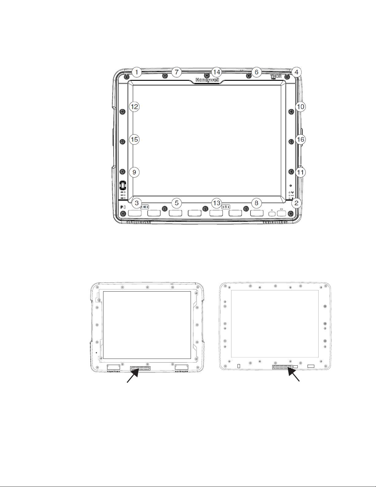
3. Place the computer face down on a clean, well-lit, and stable surface.
Note: VM3A depicted in illustration above

2 Thor VM3/VM3A Front Panel Replacement Instructions
4. Use a #2 Phillips bit to loosen the captive M3 screws on the access panel.
5. Remove the access panel from the opening and press the UPS Battery
disconnect button.
6. Reinstall the access panel cover and torque the M3 screws to 7.0 ± 0.5 inch
pounds using a #2 Phillips bit.
7. Turn the computer face up.
VM3 VM3AVM3A
Caution: Do not push the PM_RESIN_N button.
VM3
VM3A
Shipping
Mode
Button

Thor VM3/VM3A Front Panel Replacement Instructions 3
8. Use a #2 Phillips bit to loosen the 16 captive M3 screws that hold on the front
panel.
9. Carefully lift the front panel away from the device.
10. Position the replacement front panel so the wiring connector on the back of the
front panel lines up with the wiring connector on the computer.
11. Gently press the front panel into place. Ensure there are no gaps between the
front of the panel and the computer.
12. Tighten the 16 captive M3 screws in the order shown in the figure for Step 8
above. Use a #2 Phillips bit and torque the screws to 7.0 ± 0.5 inch pounds.

4 Thor VM3/VM3A Front Panel Replacement Instructions
13. Reinstall the computer in the dock, the UPS battery will reconnect
automatically.
14. Press the Power button on the front of the device.
15. If adding or removing a defroster, it is very important to wait a few moments
after powering on the device for the computer to detect the defroster. Once
detected, you can update the configuration:
• For the VM3: select Start > Settings > Control Panel > Peripherals and tap
the Test button
•FortheVM3A:selectSettings > Defroster, modify the defroster parameters,
then tap Update to apply the changes and tap OK.
16. Close any open control Panel windows.
17. The computer is ready to use.

Other manuals for Thor VM3
6
This manual suits for next models
1
Table of contents