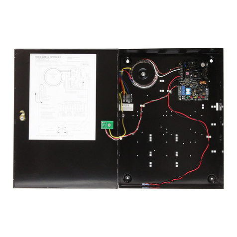
2PMB-AUX(-RTO) Power Supplies— P/N LS10242-000GE-E:B 5/4/2022
2 Specifications
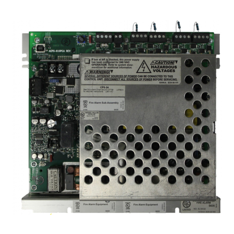
AC power: 2.5A 120VAC 50/60 HZ, 1.25A 240VAC 50/60 Hz
24VDC aux outputs: Power-limited (Class 2) 24V @ 1.5A each, Special Applications Aux Power, Aux 1 Class A/B, Aux 2 Class B only
NAC outputs (power-limited): Special Applications Class A/B NAC Power, Class D Door Holder Power, 1.5A Special Applications, 150mA Regu-
lated, Class A/B Aux Power, UZC
CLP Bus connections: carry CLP data and internal 24V power to the SLM-318 loop cards and the core board on the FACP CPU assembly. PMBs use
only the CLP data.
Secondary power (battery) charging circuit:
• Sealed lead-acid battery charger which will charge 7-100 AH batteries
• Charging current: 1A, 2A, and 4.25A
• Charging voltage: 27.6 VDC nominal
PMB battery charging configurations available (configured in VeriFire Tools):
• No charger
• Low (7-26AH)
• Medium (33-55AH)
• High (100AH)
3 Installation
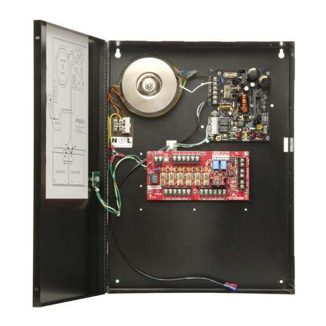
The main FACP assembly should be mounted in the top row of the cabinet. Due to cable length restrictions, the PMB-AUX(-RTO) must be mounted in
the second position of the backbox. If installing two PMB-AUX(-RTO) power supplies, the second unit must be mounted in the third position. A max-
imum of two PMB-AUX(-RTO) units is allowed
Wiring methods used shall be in accordance with Standard for Installation and Classification of Burglar and Holdup Alarm Systems, UL 681.
3.1 Requirements
• Installations are to be indoors only, in dry locations, protected from rain, water, and rapid changes in temperature that could cause condensation.
• Equipment must be securely mounted on rigid, permanent walls.
• Operating temperature shall not exceed the range of 32° to 120° F (0 to 49° C).
• Operating humidity not to exceed 93% +/- 2% non-condensing at 100° F (38° C).
• Adequate space must be available around the installation to allow easy access for operation and servicing.
• All sub-assemblies and components are to be located in compliance with local and national codes.
• All installation field wiring shall be in compliance with local and national codes.
WARNING: HIGH VOLTAGE PRESENT
REMOVE ALL SOURCES OF POWER BEFORE SERVICING, REMOVING, OR INSTALLING ANY UNITS. ENSURE TO
INSTALL THE SNAP-ON COVER OVER TB1 AFTER WIRING.
CAUTION: STATIC SENSITIVE EQUIPMENT
THE CIRCUIT BOARD CONTAINS STATIC-SENSITIVE COMPONENTS. ALWAYS USE PROPER GROUNDING DEVICES
SUCH AS A WRIST STRAP BEFORE HANDLING ANY BOARDS SO THAT STATIC CHARGES ARE REMOVED FROM THE
BODY. USE STATIC SUPPRESSIVE PACKAGING TO PROTECT ELECTRONIC ASSEMBLIES.
