manuals.online logo
Brands
  1. Home
  2. •
  3. Brands
  4. •
  5. Honeywell
  6. •
  7. Power Supply
  8. •
  9. Honeywell VX89301PWRSPLY User manual

Honeywell VX89301PWRSPLY User manual

162847-0001 Rev J 10/15 © 2009-2015 Honeywell International Inc. All Rights Reserved. Page 1
DC-to-DC Power Supply Installation Instructions
For use with the models listed below. These models can be identified by a lid with screws on the top of the lid. These models listed
below may be obsolete.
These models may be used to replace the obsolete power supplies. Contact Honeywell Technical Support or go to
www.honeywellaidc.com for DC/DC power supply installation instructions for the replacement models listed below.
Connecting electrical cables to power sources
The DC-to-DC power supply is used to power certain vehicle-mount computers (VMCs) or to provide vehicle power to certain hand-held
computers (HHCs) when placed in a DC powered vehicle dock or cradle.
Please refer to the appropriate wiring schematic on the following pages for wiring colors and connections:
Figures 1a and 1b – Thor VX8 and Thor VX9 Vehicle Mounted Computers
Figures 2a and 2b – Thor VM1, Thor VM2 and Thor VM3 Vehicle Mounted Computers
Figure 3 – Marathon Vehicle Dock
Figure 4 – MX3Plus, MX7, MX7 Tecton and MX9 Vehicle Mounted Cradles
VX89301PWRSPLY – Power Supply, DC/DC, 9 to 36V 9000301PWRSPLY – Power Supply, 18-60VDC with cable
VX89A302PSDC48V – Power Supply, DC/DC, 18 to 60V 9000302PWRSPLY – Power Supply, 60-110VDC with cable
VX89303PWPSPLY – Power Supply, DC/DC, 60 to 110V
9000311PWRSPLY – Power Supply, 9-60VDC, 60W 9000313PWRSPLY – Power Supply, 50-150VDC, 60W
Specifications for electrical supply
Input Voltage Always observe input voltage range specified on the DC-to-DC power supply and the optional screen blanking box
(for vehicle mounted terminals only).
Output Voltage 12 VDC ± 10%
Power 75 W
Fuse
Tecton, MX9, MX3 Plus, MX7: Use a 5 A slow blow fuse.
Thor VX8, Thor VX9, Marathon: Use a 10 A slow blow fuse
Thor VM1, Thor VM2, Thor VM3: Use VM3055FUSE (or equivalent) to install the fuse as shown below:
•For12VDC input, use the 10A fuse from the kit or a slow blow fuse that has a DC voltage rating greater than 12VDC.
•For24VDC input, use the 6A fuse from the kit or a slow blow fuse that has a DC voltage rating greater than 24VDC.
•For36VDC input, use the 4A fuse from the kit or a slow blow fuse that has a DC voltage rating greater than 36VDC.
•For48VDC input, use the 3A fuse from the kit or a slow blow fuse that has a DC voltage rating greater than 48VDC.
Screen Blanking Box: Use a 3 A fuse
Caution: For proper and safe installation, the input power cable must be connected to a fused circuit on the vehicle. This fused
circuit requires a user supplied 5 or 10 Amp maximum time delay (slow blow, see table above for fuse rating) high
interrupting rating fuse. If the supply connection is made directly to the battery, the fuse should be installed in the
positive lead within 5 inches of the battery positive (+) terminal.
Caution The VX power supplies are sealed per IPXX. Usage in areas where moisture can affect the power supply connections
should be avoided. The power supply should be mounted in a dry location within the vehicle or placed in a suitable
protective enclosure.
Caution:
For installation by trained service personnel only.
Warning: Risk of ignition or explosion. Explosive gas mixture may be vented from battery. Work only in well ventilated area.
Avoid creating arcs and sparks at battery terminals.
!
!
!
!
162847-0001 Rev J 10/15 © 2009-2015 Honeywell International Inc. All Rights Reserved. Page 2
Connecting the Vehicle Electrical Connection
Please review the proper wiring illustration, later in this document, before beginning power cable install. If connecting a VMC, the com-
puter must be powered off. If connecting a HHC cradle/dock, the cradle must be empty.
1. Connect the power cable to the VMC or the HHC cradle.
2. Route the cable from the VMC or HHC cradle to the DC-to-DC converter and, optionally for some VMCs, to the screen blanking box.
3. Cut the cable to length and strip the wire ends. If the screen blanking feature is not used for the Thor VX8 or Thor VX9, do not strip
the green and yellow wires.
4. Route the power cable the shortest way possible. The cable is rated for a maximum temperature of 105°C (221°F). When routing
this cable, it should be protected from physical damage and from surfaces that might exceed this temperature. Do not expose the
cable to chemicals or oil that may cause the wiring insulation to deteriorate. Always route the cable so that it does not interfere with
safe operation and maintenance of the vehicle.
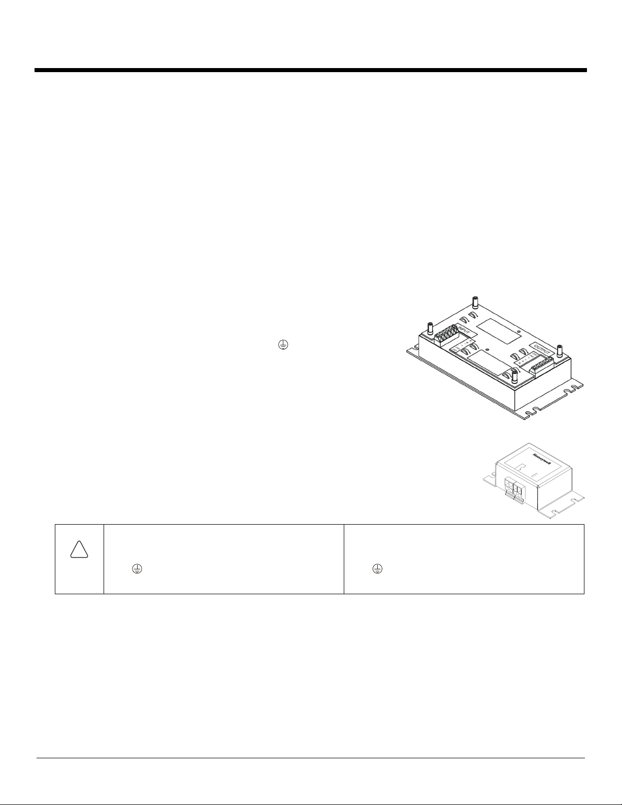
5. Remove the lid from the DC-to-DC converter.
6. Strip the ends of the wires in the cable from the VMC or HHC cradle and attach the wire ends to the output side of the DC-to-DC
converter.
7. Strip the ends of the wires in the cable that will connect to vehicle power and attach
the wire ends to the input side of the DC-to-DC converter.
Note: The input and output blocks each have two + and two – minus connectors.
Either connector in the block can be used to connect the matching polarity wire.
The input and output blocks also each have two (chassis
ground).connections. When the diagram indicates a chassis ground
connection, use either chassis ground connector in each block.
Note: Wire colors depend on the type of device attached. Please refer to the
illustrations later in this document for wire colors.
8. Use looms and wire ties to secure all wiring as shown.
9. Reattach the cover with the screws.
10. If the screen blanking box is used for a Thor VX8 or Thor VX9 installation, attach the stripped green and
yellow wire ends to the box. Refer to the applicable following diagram for proper wiring connection.
11. If the screen blanking box is used for a Thor VM1 or Thor VM2 installation, connect a serial cable from
the COM port on the Mount Smart Dock to the box. Refer to the applicable following diagram for proper
wiring connection.
12. Connect the DC-to-DC converter to the vehicle’s electrical system.
13. While observing the fuse requirements specified above, connect the power cable as close as possible to the actual battery terminals
of the vehicle. When available, always connect to unswitched terminals in the vehicle fuse panel, after providing proper fusing.
ATTENTION:For uninterrupted power, electrical supply connections should not be made at any point after the ignition
switch of the vehicle.
14. If the screen blanking box is used for a VMC installation, connect the box to vehicle motion circuitry and ground. Refer to the
applicable following diagram and the label on the screen blanking box for proper wiring connection.
15. Use proper electrical and mechanical fastening means for terminating the cable. Properly sized “crimp” type electrical terminals are
an accepted method of termination. Select electrical connectors sized for use with 18AWG (1mm2) conductors.
16. Provide mechanical support for the cable by securing it to the vehicle structure at approximately one foot intervals, taking care not to
over tighten and pinch conductors or penetrate the outer cable jacket.
Caution: For battery powered vehicles:
+ is connected to battery positive.
- must be connected to battery negative.
GND must be connected to the vehicle chassis
ground.
For internal combustion engine powered vehicles:
+ is connected to battery positive.
- is connected to battery negative.
GND is connected to the vehicle chassis ground,
which can also be battery negative.
GN D
12-72V
!
162847-0001 Rev J 10/15 © 2009-2015 Honeywell International Inc. All Rights Reserved. Page 3
Figure 1a – Thor VX8 and Thor VX9 Vehicle Mounted Computers
Figure 1b – Optional Screen Blanking Connections
Screen blanking is configured via the Display Backlight tab of the VMT Manager option in the Windows Control panel.
With Screen Blanking Box With User Supplied Switch / Relay
Connect to existing motion circuitry on vehicle – any 12-60 or 12-72
VDC signal triggered by vehicle motion.
Refer to the label on the Screen Blanking Box for allowable voltage
input range.
User supplied switch/relay that supplies
electrical conductive connection on vehicle
motion
Supplied Power Cable
(Sheilding to be trimmed
and connectd to GND terminal)
EXISTING CIRCUITRY ONVEHICLE
FORKLIFT BATTERY
MAINSWITCH
Thor VX8or Thor VX9
VEHICLE
MOUNTED
COMPUTER
Circular
Power
Connector
10A slowfuse
Close to power
source
+Vo-Vo
ISOLATED
DC/DC
5
6
1
3
GREEN
YELLOW
BROWN
WHITE
Optional screen blanking
connection, see options below
Leaveunconnected if not
using screen blanking
-Vi
-Vo
ISOLATED
DC/DC
-Vi
+Vo
ISOLATED
DC/DC
+Vi
GND
GND
MOTION
CIRCUITRY
To -Voonvehicle,
i.e. Negative
battery terminal
3A fuse
+Vi
GND
To vehicle
mounted
computer
GREEN
YELLOW
To vehicle
mounted
computer
GREEN
YELLOW
Switch
162847-0001 Rev J 10/15 © 2009-2015 Honeywell International Inc. All Rights Reserved. Page 4
Figure 2a – Thor VM1, Thor VM2, and Thor VM3 Vehicle Mounted Computers
Figure 2b – Optional Screen Blanking Connections
The user must supply the serial cable for the screen blanking connection. Only pins 7 and 8 are used for the screen blanking connection.
Screen Blanking is configured via the Screen Control (Thor VM1 and Thor VM2) or the ZoomZone (Thor VM3) option in the Windows
Control Panel.
With Screen Blanking Box With User Supplied Switch / Relay
Connect to existing motion circuitry on vehicle – any 12-60 or 12-72 VDC
signal triggered by vehicle motion.
Refer to the label on the Screen Blanking Box for allowable voltage input
range.
Connect switched terminal on blanking box to Pin 7 of COM port.
User supplied switch/relay that supplies
electrical conductive connection on vehicle
motion
Thor VM1, Thor VM2
or Thor VM3
VEHICLE
MOUNTED
COMPUTER
in Smart Doc
EXISTING CIRCUITRY ONVEHICLE
FORKLIFT BATTERY
MAINSWITCH
Circular
Power
Connector
on Dock
-Vi
-Vo
-Vo
ISOLATED
DC/DC
8
RED
BLACK
GREEN
BLUE
(not connected)
+VoCOM1 or COM2
Connector
on Dock
7
1
2
3
4
5
6
-Vi
+Vo
ISOLATED
DC/DC
+Vi
GND
GND
User supplied serial
cable for optional
screen blanking
connection,
see below
See text for fuse
requirements
Close to power
source
MOTION
CIRCUITRY
To -Voonvehicle,
i.e. Negative
battery terminal
3A fuse
+Vi
GND
To pin 7 of COM1 or COM2
To pin 8of COM1 or COM2
Switch
To pins 7 and 8
of COM1 or COM2
port on Thor VM1
or Thor VM2 dock
162847-0001 Rev J 10/15 © 2009-2015 Honeywell International Inc. All Rights Reserved. Page 5
Figure 3 – Marathon Vehicle Dock
Separate the blue/black twisted wires.
Connect one of the wires to a –Vo terminal and the other to a (chassis ground) terminal on the DC-to-DC power supply.
Figure 4 – MX3Plus, MX7, MX7 Tecton and MX9 Vehicle Cradles
EXISTING CIRCUITRY ONVEHICLE
FORKLIFT BATTERY
MAINSWITCH
Marathon
VEHICLE
MOUNTED
COMPUTER
DOCK
Circular
Power
Connector
on Dock
-Vi
-Vo
-Vo
ISOLATED
DC/DC
BROWN/WHITE TWISTED WIRE
BLUE/BLACK TWISTED WIRE
+Vo
-Vi
+Vo
ISOLATED
DC/DC
+Vi
GND
GND
10A slowfuse
Close to power
source
EXISTING CIRCUITRY ONVEHICLE
FORKLIFT BATTERY
MAINSWITCH
VEHICLE
MOUNTED
CRADLE
-Vi
-Vo
-Vo
ISOLATED
DC/DC
+Vo
-Vi
+Vo
ISOLATED
DC/DC
+Vi
GND
GND
5A slowfuse
Close to power
source
BROWN
BLUE
GREEN
RED/WHITE
RED/BLACK
GREEN
Use color scheme
corresponding to
inputwire provided
162847-0001 Rev J 10/15 © 2009-2015 Honeywell International Inc. All Rights Reserved. Page 6
Disclaimer
Honeywell International Inc. (“HII”) reserves the right to make changes in specifications and other information contained in this document
without prior notice, and the reader should in all cases consult HII to determine whether any such changes have been made. The infor-
mation in this publication does not represent a commitment on the part of HII.
HII shall not be liable for technical or editorial errors or omissions contained herein; nor for incidental or consequential damages resulting
from the furnishing, performance, or use of this material. HII disclaims all responsibility for the selection and use of software and/or hard-
ware to achieve intended results.
This document contains proprietary information that is protected by copyright. All rights are reserved. No part of this document may be
photocopied, reproduced, or translated into another language without the prior written consent of HII.
2009-2015 Honeywell International Inc. All rights reserved.
Other product names or marks mentioned in this document may be trademarks or registered trademarks of other companies and are the
property of their respective owners.
Web Address: www.honeywellaidc.com
Patents
For patent information, please refer to www.hsmpats.com.
Technical Assistance
Contact information for technical support, product service, and repair can be found at www.honeywellaidc.com.
Limited Warranty
Refer to www.honeywellaidc.com/warranty_information for your product’s warranty information.
User Documentation
To download user documentation go to www.honeywellaidc.com.

This manual suits for next models

6

Other Honeywell Power Supply manuals

Honeywell 208414 User manual

Honeywell

Honeywell 208414 User manual

Honeywell HPF24S8 User manual

Honeywell

Honeywell HPF24S8 User manual

Honeywell PRO32E1PS Instruction manual

Honeywell

Honeywell PRO32E1PS Instruction manual

Honeywell HPF-PS6 User manual

Honeywell

Honeywell HPF-PS6 User manual

Honeywell Notifier AMPS-24/E User manual

Honeywell

Honeywell Notifier AMPS-24/E User manual

Honeywell PS1202A User manual

Honeywell

Honeywell PS1202A User manual

Honeywell HP300ULM Technical manual

Honeywell

Honeywell HP300ULM Technical manual

Honeywell Gamewell FCI GFPS-9 User manual

Honeywell

Honeywell Gamewell FCI GFPS-9 User manual

Honeywell HP300ULX Technical manual

Honeywell

Honeywell HP300ULX Technical manual

Honeywell PEHA D 942 SPV User manual

Honeywell

Honeywell PEHA D 942 SPV User manual

Honeywell HPF24S8 Technical manual

Honeywell

Honeywell HPF24S8 Technical manual

Honeywell HP1205UL-4 Technical manual

Honeywell

Honeywell HP1205UL-4 Technical manual

Honeywell HP400ULM Technical manual

Honeywell

Honeywell HP400ULM Technical manual

Honeywell NOTIFIER APS2-6R/E User manual

Honeywell

Honeywell NOTIFIER APS2-6R/E User manual

Honeywell HP600ULM User manual

Honeywell

Honeywell HP600ULM User manual

Honeywell Fire-Lite FL-PS6 User manual

Honeywell

Honeywell Fire-Lite FL-PS6 User manual

Honeywell HPTV24-E Series Technical manual

Honeywell

Honeywell HPTV24-E Series Technical manual

Honeywell HP312CX User manual

Honeywell

Honeywell HP312CX User manual

Honeywell DCPSU-24 User manual

Honeywell

Honeywell DCPSU-24 User manual

Honeywell GENT VCS-PSU-N User manual

Honeywell

Honeywell GENT VCS-PSU-N User manual

Honeywell SILENT KNIGHT SK-PS6 User manual

Honeywell

Honeywell SILENT KNIGHT SK-PS6 User manual

Honeywell HP24100ULWP User manual

Honeywell

Honeywell HP24100ULWP User manual

Honeywell TC-RPCXX1 User manual

Honeywell

Honeywell TC-RPCXX1 User manual

Honeywell HPL624 Technical manual

Honeywell

Honeywell HPL624 Technical manual

Popular Power Supply manuals by other brands

Owon ODP Series user manual

Owon

Owon ODP Series user manual

LITELINE LED-HWB-24V-100W quick start guide

LITELINE

LITELINE LED-HWB-24V-100W quick start guide

Simplex Watt-Muncher manual

Simplex

Simplex Watt-Muncher manual

Antec SMARTPOWER 2.0 user manual

Antec

Antec SMARTPOWER 2.0 user manual

Trivum RP321 Quick installation guide

Trivum

Trivum RP321 Quick installation guide

Siemens 4AV2306-2EB00-0A operating instructions

Siemens

Siemens 4AV2306-2EB00-0A operating instructions

ABB 4234 600 instruction manual

ABB

ABB 4234 600 instruction manual

Meech Hyperion 906 operating manual

Meech

Meech Hyperion 906 operating manual

MGE UPS Systems EPS 7000 user manual

MGE UPS Systems

MGE UPS Systems EPS 7000 user manual

Bentel Security BXM24/25-U manual

Bentel Security

Bentel Security BXM24/25-U manual

Portable Power Technology 1000R-LF user manual

Portable Power Technology

Portable Power Technology 1000R-LF user manual

Antec Basiq 430 Specifications

Antec

Antec Basiq 430 Specifications

EPS NEXUS manual

EPS

EPS NEXUS manual

Pulsar BLACK POWER PSBEN 2012C manual

Pulsar

Pulsar BLACK POWER PSBEN 2012C manual

DUNIWAY Stockroom Terranova 752A instruction manual

DUNIWAY Stockroom

DUNIWAY Stockroom Terranova 752A instruction manual

PeakTech P 1525 Operation manual

PeakTech

PeakTech P 1525 Operation manual

Nac PS01 General description and installation

Nac

Nac PS01 General description and installation

JVA Z Series manual

JVA

JVA Z Series manual

manuals.online logo
manuals.online logoBrands
  • About & Mission
  • Contact us
  • Privacy Policy
  • Terms and Conditions

Copyright 2025 Manuals.Online. All Rights Reserved.