manuals.online logo
Brands
  1. Home
  2. •
  3. Brands
  4. •
  5. Honeywell
  6. •
  7. Security Sensor
  8. •
  9. Honeywell 5800FLOOD User manual

Honeywell 5800FLOOD User manual

5800FLOOD
Flood Detector & Temperature Sensor / Détecteur d'inondation et capteur
de température
INSTALLATION INSTRUCTIONS
INSTRUCTIONS D INSTALLATION
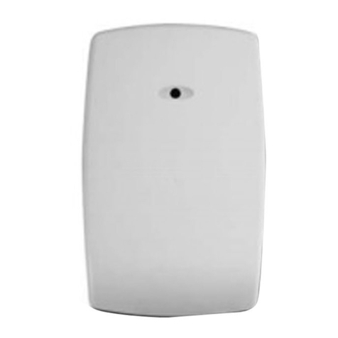
The 5800FLOOD Flood Detector & Temperature Sensor is a
wireless transmitter used with Honeywell’s alarm systems that
support 5800 series devices Applications include bathrooms,
laundry rooms, boilers and basements etc
The 5800FLOOD:
• can serve as a hot and/or cold temperature sensor via
internal thermal sensor
(sends alarm to control when temperature is lower than 45°F
(Cold condition) or above 95°F, (Hot condition)
• can serve as a Water leakage or Flood Detector via built-in
metal contacts on the bottom of the unit (sends alarm to
control within 20 seconds nominal to 25 seconds maximal
after water has come in contact with the metal probes )
• does not require external probes
• functions (modes) set by programming pre-defined device
loop numbers (see table 1) to separate zones in the control
panel
• provides tamper supervision, which sends a trouble signal to
the control if the unit’s cover is removed
INSTALLATION
Check Signal Strength: After enrolling, verify adequate signal
strength by conducting Go/No Go tests (see the controller’s
instructions) with the device in its intended mounting location
Adjust the device location and orientation as necessary
Le détecteur d'inondation 5800FLOOD avec capteur de température
sans fil utilisé avec les systèmes d'alarme Honeywell prennent en
charge les appareils de la série 5800 Les applications comprennent
les salles de bain, les salles de lavage, les salles de chaudières, les
sous-sols, etc
Le 5800FLOOD :
• peut servir de capteur de température chaude et/ou froide grâce à
son capteur thermique interne
(transmet une alarme au panneau de commande lorsque la
température est en-dessous de 7,2 °C / 45 °F (condition de froid)
ou au-dessus de 35 °C / 95 °F (condition de chaleur)
• peut servir de détecteur de fuite d'eau ou d'inondation grâce à ses
contacts métalliques intégrés dans le bas de l'unité (transmet une
alarme au panneau de commande dans les 20 secondes nominal à
25 secondes maximum qui suivent après que l'eau soit entrée en
contacts avec les sondes métalliques)
• ne nécessite pas de sonde externe
• fonctions (modes) réglées par la programmation définie à l'avance à
l'aide des numéros de boucle (voir le Tableau 1) à des zones
distinctes du panneau de commande
• offre la supervision de sabotage qui transmet un signal de
défectuosité au panneau de commande lorsque que le couvercle de
l'unité est retiré
INSTALLATION
Force du signal: Après l'enrôlement, vérifiez la puissance du signal
adéquate en effectuant des tests Go / No Go (voir les instructions du
panneau de commande) avec le dispositif dans son emplacement de
montage prévu Au besoin, modifiez l'emplacement ou l'orientation du
dispositif
5800FLOOD -001
➜
Observe polarity
Observez la polarité
Panasonic CR123A,
Duracell DL123A,
Huiderui CR123A or
Honeywell 466.
Tamper Switch
Antisabotage
5800FLOOD -002-V0
➜
Water Leak Detection
Place the device on the floor or other desired location near any
area that
potentially can be subject to a water leak condition
(ex floor near or inside a kitchen cabinet, near the base of a
refrigerator, in a bathroom, basement, etc )
Make sure the metal contacts at the bottom of the enclosure
are clean and free of any
debris before positioning the unit in
place
IMPORTANT: After a water leak detection event, make sure the
contacts and the unit are completely dry and free of any
debris
before relocating the device
Tem erature Sensing
If used solely as a temperature sensor, mount the device low
on a wall in the desired location with double-sided adhesive
tape (supplied)
Détection de fuite d'eau
Placez le dispositif sur le plancher où à tout autre endroit désiré près
de toute zone qui peut potentiellement présenter une condition de
fuite d'eau (par ex , un plancher près où à l'intérieur d'une armoire de
cuisine, près de la base d'un réfrigérateur, dans une salle de bain, dans
un sous-sol, etc )
Assurez-vous que les contacts métalliques qui se trouvent dans le bas
de l'unité sont propres et exempts de tout débris avant de mettre l'unité
en place
IMPORTANT : Après une activité de détection de fuite d'eau, assurez-
vous que les contacts et l'unité sont complètement secs et exempts de
tout débris avant de remettre le dispositif à un autre endroit
Détection de la tem érature
Installez le dispositif sur le bas du mur à l'endroit désiré en le faisant
adhérer à l'aide du ruban autocollant double-face (fourni)
IMPORTANT
:
•
Do not install this device on or near metal objects, Avoid locating
the device near wiring such as AC, telephone, HVAC, computer data
cables, etc
• Avoid mounting the detector near heat generating devices (e g
ovens, heat vents,
furnaces, boilers) or on a metal cabinet
• DO NOT remove the circuit board from the back case
IMPORTANT
:
•
N'installez pas ce dispositif sur ou près d'objets en métal, comme
une prise de courant ou de téléphone, un système de CVCA, de
câbles de données d'ordinateur, etc
• Évitez d’installer le détecteur près d’appareils générant de la chaleur
(p ex , des fours, des évents de chaleur, des fournaises, des
chaudières) ainsi que d'armoire ou boîtier en métal
•
NE RETIREZ PAS le circuit du boîtier arrière
PROGRAMMING (Setting the Operating Mode)
Table 1 lists the functions of the 5800FLOOD with their respective
loop numbers
Program each desired loop function as a separate zone in the control
panel
1 Enter the control’s Zone Programming mode
2 Assign a zone number for each loop used
Zone Type = choose a zone type based on desired operation (ex
24-Hr Aux, Waterflow)
Input Type = 03 (Supervised RF)
3 When prompted for the serial number, press and release the unit’s
tamper switch twice
Enter the appropriate loop number for the type of zone being
enrolled (loop number initially appears as loop 4)
Loop = 1, 2, or 3 (see table for loop functions)
Alternatively, you can manually enter the sensor serial number
found on the unit’s label
PROGRAMMATION (Réglage du mode de
fonctionnement)
Le Tableau 1 énumère les fonctions du 5800FLOOD et de ses
numéros de boucles respectifs
Programmez chaque boucle de fonction désirée à titre de zone
distincte dans le panneau de commande
1 Entrez dans le mode de programmation des zones du panneau
2 Assignez un numéro de zone pour chaque boucle utilisée
Type de zone = choisissez un type de zone en vous basant sur le
fonctionnement désiré (par ex , 24 h Aux, débit d'eau)
Type d’entrée = 03 (RF supervisé)
3 Lorsque le numéro de série vous est demandé, appuyez et relâchez
l'interrupteur antisabotage de l'unité à deux reprises
Entrez le numéro de boucle approprié pour le type de boucle à
enrôler (le numéro de boucle qui apparaît par défaut est le 4)
Boucle = 1, 2 ou 3 (voir le tableau des fonctions des boucles)
Autrement, vous pouvez entrer manuellement le numéro de série
du capteur qui se trouve sur l'étiquette de l'unité
Table 1
Mode Loo Fault Occurs When After… Restore when … After…
Flood Loop 3 probe contacts water 20-25
seconds
nominal
no contact with water and
contacts are dry 20-25 seconds nominal
Tem erature
Tem erature is..
Tem erature is..
Cold Loop 1 below 45°F (7°C) 15 min above 45°F (7°C) 15 min
Hot Loop 2 above 95°F (35°C) below 95°F (35°C)
Tableau 1
(Français)
Mode Boucle Une violation se roduit
quand
A rès... Rétablissement quand ... A rès...
Inondation Boucle 3
contacts de la sonde d'eau 20-25
secondes
nominales
aucun contact avec de
l'eau et les contacts sont
secs
20-25 secondes
nominales maximum de
60 secondes
Tem érature
La tem érature est..
Froide Boucle 1
en-dessous de 7 °C (45 °F)
15 min
au-dessus de 7 °C (45 °F)
15 min
Chaude Boucle 2
au-dessus de 35 °C (95 °F) en-dessous de 35 °C
(95 °F)
TESTING
1
With the control panel in Test mode, remove & replace device cover
to activate
2 System keypad should beep and display each programmed zone
(loop)
3 Exit control’s test mode
Water Test
After sensor is enrolled, dip the metal water sensing probes into a
container of tap water The sensor reports an alarm within 20-25
seconds
After testing, clean and dry the metal probes, and place device where
appropriate
MAINTAINING PROPER OPERATION
To maintain the detector in proper working condition, it is
important that you observe the
following:
• Replace the battery when a low battery condition is reported
• Make sure the unit is situated flat on the floor, or any other surface
and make sure
the contacts are not blocked by debris or dirt as these
will affect conductivity of water
in the area
• Clean and dry the metal probes before reusing the device following
the water leak
detection
• It is recommended to get the advice of the alarm company to
relocate the device
TEST
1 Alors que le panneau de commande est dans le mode de Test,
retirez et replacez le couvercle du dispositif pour l'activer
2 Le clavier du système devrait émettre un bip et afficher chaque
zone programmée (boucle)
3 Quittez le mode de test du panneau de commande
Test d'eau
Trempez les sondes de détection d'eau en métal dans un récipient
d'eau du robinet Le capteur signale une alarme dans les 20-25
secondes
Après les tests, nettoyez et séchez les sondes métalliques et placez
l'appareil le cas échéant
MAINTIEN D UN BON FONCTIONNEMENT
Afin de maintenir le bon fonctionnement du détecteur, il est important
de suivre les recommandons suivantes :
• Replacez la pile lorsqu'une condition de pile faible est signalée
• Assurez-vous que l'unité est placée à plat sur le plancher ou toute
autre surface et assurez-vous que les contacts ne sont pas obstrués
par tout débris ou poussière car ceci pourrait nuire à la conductivité
de l'eau dans cette zone
• Nettoyez et asséchez les sondes de métal avant de réutiliser le
dispositif à la suite de la détection d'une condition de fuite d'eau
• Il est recommandé d'obtenir l'avis de l'entreprise d'alarme avant
d'installer le dispositif à un autre endroit
BATTERY REPLACEMENT
After removing the battery; wait at least 30
seconds before installing the new one Use
only the following 3V Lithium batteries:
• Panasonic CR123A • Huiderui CR123A
• Duracell DL123A • Honeywell 466
CAUTION: Risk of fire, explosion, and burns Do
not recharge, disassemble, heat above 212°F
(100°C) or incinerate Dispose of used batteries
properly Keep away from children
NOTE: Constant exposure to high or low
temperature or high humidity may reduce battery
life
1
2
5800FLOOD -003
Remplacement de la pile
Après avoir retiré la pile; attendez 30 secondes
avant d'installer la nouvelle Utilisez
uniquement les piles au lithium de 3V
suivantes :
• Panasonic CR123A • Huiderui CR123A
• Duracell DL123A • Honeywell 466
Attention de batterie : Risque d'incendie,
d'explosion et de brûlures Ne rechargez pas,
démonter, chauffer au-dessus de 212° F (100°C),
ou incinérer Débarrassez-vous des batteries
utilisées de façon appropriée Gardez à partir des
enfants
NOTE : Une exposition constante à des
températures élevées ou basses ou à un taux
d'humidité élevée peut réduire la durée de vie de la
pile
SPECIFICATIONS
Battery Type 3V Lithium, CR123A
(battery life ~4-5 years)
Standby Current 3µA maximum
Consumption
Low Battery Detection 2 8V ±20mV
Unit (Battery) Shut Down 1 8V ±20mV
RF Frequency 344 94MHZ (5800 protocol)
RF Range 200ft (60m) nominal indoors
from wireless transmitters (the
actual range to be determined
with the security system in the
Test mode)
Operational Temperature 14°F to 104°F (-10°C to +40°C)
Cold- Hot Alert detection < 45°F for Cold, and ≥ 95°F for
Hot
(<7 2°C for Cold, and ≥ 35°C for
Hot)
Water Sensing Probes Stainless steel contacts
Water Leak Detection Reports alarm within 20-25
seconds
Dimensions 3 1” L x 1 6” W x 2 0” D max
(7 9cm L x 4 1mm W x 5 8mm D max )
REFER TO THE INSTALLATION INSTRUCTIONS FOR
THE CONTROL WITH WHICH THIS DEVICE IS USED,
FOR DETAILS REGARDING LIMITATIONS OF THE
ENTIRE ALARM SYSTEM.
Spécifications
Pile
3V au lithium, CR123A
(longévité de la pile : de 4 à 5 ans)
Courant de veille
3µ A maximum
Consommation
Détection de pile faible
2,8 V à ± 20 mV
Arrêt de l'unité (pile trop faible)
1,8 V à ± 20 mV
Fréquence RF
344,94 MHz (protocole 5800)
Portée RF à 60 m (200 pi) nominale pour les
transmetteurs sans fil intérieurs
(la portée actuelle doit être
déterminée dans le mode de test
du système de sécurité)
Température de fonctionnement de -10 °C à 40 °C (14 °F
à 104 °F)
Détection d'alerte de froid et de chaleur
< 7 °C pour le froid,
et ≥ 35 °C pour la
chaleur
(45 °F pour le froid,
et ≥ 95 °F pour la
chaleur)
Sondes sensibles à l'eau
Contacts en acier inoxydable
Détection de fuite d'eau
Signalement d'alarme dans les 20
à 25 secondes
Dimensions 3 1” L x 1 6” W x 2 0” D max
(7 9cm L x 4 1mm W x 5 8mm D max )
POUR LES DÉTAILS CONCERNANT LES LIMITATIONS
DU SYSTÈME DANS SON ENSEMBLE, REPORTEZ-VOUS
AUX INSTRUCTIONS D’INSTALLATION DU PANNEAU DE
COMMANDE AVEC LEQUEL LE DISPOSITIF EST UTILISÉ.
FCC / ISED STATEMENT
FEDERAL COMMUNICATIONS COMMISSION & ISED STATEMENTS
The user shall not make any changes or modifications to the equipment unless authorized by the Installation Instructions or User's
Manual Unauthorized changes or modifications could void the user's authority to operate the equipment
This device complies with Part 15 of the FCC rules and ISED’s license-exempt RSSs Operation is subject to the following two
conditions: (1) This device may not cause harmful interference, and (2) this device must accept any interference received, including
interference that may cause undesired operation
Unauthorized changes or modifications could void the user's authority to operate the equipment
Cet appareil est conforme à la partie 15 des règles de la FCC & et exempt de licence RSS d’ISED Son fonctionnement est soumis aux
conditions suivantes: (1) Cet appareil ne doit pas causer d’interférences nuisibles (2) Cet appareil doit accepter toute interférence reçue
y compris les interférences causant une réception indésirable
Support and Warranty / Soutien et Garantie
For online support inf
ormation, please go to: https://mywebtech honeywell com/
Pour de l’assistance en ligne, visitez : https://mywebtech honeywell com/
For the latest warranty information, go to: www honeywell com/security/hsc/resources/wa
Pour les dernières informations de garantie, s'il vous plaît aller à :
www honeywell com/security/hsc/resources/wa
For patent information, see www honeywell com/patents
Pour des informations sur les brevets, voir www honeywell com/patents
MyWebTech
Warranty
Garantie
Patents
Brevets
2 Corporate Center Drive, Suite 100
P O Box 9040, Melville, NY 11747
 2017 Honeywell International Inc
www honeywell com/security
Honeywell is a registered trademark of Honeywell International Inc All
other trademarks are the properties of their respective owners All
rights reserved
Honeywell des marque déposée de Honeywell International Inc Toutes
les autres marques de commerce appartiennent à leurs propriétaires
respectifs Tous droits réservés
In Canada
3333 Unity Drive
Mississauga, Ontario L4L 7Z4
© Honeywell International Inc , 2017
Ê800-23123jŠ
800-23123 8/17 Rev A

Other Honeywell Security Sensor manuals

Honeywell SiX Series User manual

Honeywell

Honeywell SiX Series User manual

Honeywell 5800COMBO User manual

Honeywell

Honeywell 5800COMBO User manual

Honeywell Small SATCOM Instruction Manual

Honeywell

Honeywell Small SATCOM Instruction Manual

Honeywell OMV-VX Series User manual

Honeywell

Honeywell OMV-VX Series User manual

Honeywell 14506873-001 User manual

Honeywell

Honeywell 14506873-001 User manual

Honeywell ADEMCO 5808EU User manual

Honeywell

Honeywell ADEMCO 5808EU User manual

Honeywell 997 User manual

Honeywell

Honeywell 997 User manual

Honeywell Notifier NRX-TFIX58 User manual

Honeywell

Honeywell Notifier NRX-TFIX58 User manual

Honeywell SPM Flex User manual

Honeywell

Honeywell SPM Flex User manual

Honeywell IQ Force Installation manual

Honeywell

Honeywell IQ Force Installation manual

Honeywell EXCEL ADT-HRSI User manual

Honeywell

Honeywell EXCEL ADT-HRSI User manual

Honeywell MDA Scientific MIDAS User manual

Honeywell

Honeywell MDA Scientific MIDAS User manual

Honeywell FG-730 User manual

Honeywell

Honeywell FG-730 User manual

Honeywell IS2535T User manual

Honeywell

Honeywell IS2535T User manual

Honeywell Notifier FSP-951AUS User manual

Honeywell

Honeywell Notifier FSP-951AUS User manual

Honeywell H-S81-HS User manual

Honeywell

Honeywell H-S81-HS User manual

Honeywell FlexGuard FG-1625 User manual

Honeywell

Honeywell FlexGuard FG-1625 User manual

Honeywell Eclipse Instruction Manual

Honeywell

Honeywell Eclipse Instruction Manual

Honeywell ToxiPro CO User manual

Honeywell

Honeywell ToxiPro CO User manual

Honeywell Miller DuraHoist Operator's manual

Honeywell

Honeywell Miller DuraHoist Operator's manual

Honeywell Fire Sentry FS7-2173-2RP User manual

Honeywell

Honeywell Fire Sentry FS7-2173-2RP User manual

Honeywell MIDAS-T-HTP User manual

Honeywell

Honeywell MIDAS-T-HTP User manual

Honeywell 1031030 User manual

Honeywell

Honeywell 1031030 User manual

Honeywell FireLite BG-12LSP User manual

Honeywell

Honeywell FireLite BG-12LSP User manual

Popular Security Sensor manuals by other brands

schmersal RSS 36-D manual

schmersal

schmersal RSS 36-D manual

Tecnar accuraspray CS Quick setup guide

Tecnar

Tecnar accuraspray CS Quick setup guide

SWARCO Caiman Installation

SWARCO

SWARCO Caiman Installation

Optex FMX-ST installation instructions

Optex

Optex FMX-ST installation instructions

B.E.G. LUXOMAT Indoor 180-M-2C Installation and operating instruction

B.E.G.

B.E.G. LUXOMAT Indoor 180-M-2C Installation and operating instruction

SPX Radiodetection RD7000+ Operation manual

SPX

SPX Radiodetection RD7000+ Operation manual

B.E.G. LUXOMAT PD4-M-2C-DUO Installation and operating instructions

B.E.G.

B.E.G. LUXOMAT PD4-M-2C-DUO Installation and operating instructions

Bircher Reglomat EasyMotion operating instructions

Bircher Reglomat

Bircher Reglomat EasyMotion operating instructions

SIM SIM-04 installation instructions

SIM

SIM SIM-04 installation instructions

Atal AT-VLC-ND-A2-RS user manual

Atal

Atal AT-VLC-ND-A2-RS user manual

Tractel Stopcable EN 353-1 Operating and maintenance instructions

Tractel

Tractel Stopcable EN 353-1 Operating and maintenance instructions

DSC WLS912L-900 installation instructions

DSC

DSC WLS912L-900 installation instructions

LEGRAND CP Electronics EBMHS-BLV Product guide

LEGRAND

LEGRAND CP Electronics EBMHS-BLV Product guide

LEGRAND Tynetec ZXT424 manual

LEGRAND

LEGRAND Tynetec ZXT424 manual

ESA Corona CAD Operating and maintenance manual

ESA

ESA Corona CAD Operating and maintenance manual

Omron F3SJ-B**N25 Series instruction sheet

Omron

Omron F3SJ-B**N25 Series instruction sheet

PCE Health and Fitness PCE-LDC 8 user manual

PCE Health and Fitness

PCE Health and Fitness PCE-LDC 8 user manual

Argus Security TW-DM-01/916 manual

Argus Security

Argus Security TW-DM-01/916 manual

manuals.online logo
manuals.online logoBrands
  • About & Mission
  • Contact us
  • Privacy Policy
  • Terms and Conditions

Copyright 2025 Manuals.Online. All Rights Reserved.