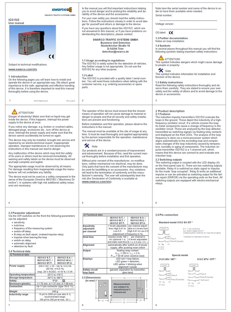
SWARCO Caiman User manual

SWARCO
CAIMAN
Junction Box Installation
CAIMAN
WIDE BEAM STOP+MOTION
RADAR DETECTOR
Caiman_JunctionBox-Installation_BE_00

www.swarco.com
SWARCO TRAFFIC SYSTEMS GMBH, Niederkircher Straße 16, D-54294 Trier, Germany
T. +49-651-21002-0, +49-651-21002-999, E. detection@swarco.de
2/20
CONTENT
1Detector Type CAIMAN (1st Generation)...................................................................................... 3
1.1 Identifying System Components..............................................................................................3
1.2 Connecting Cable and Junction Box .......................................................................................5
1.2.1 Removing the cable shielding/Preparing the braid..........................................................5
1.2.2 Removing unnecessary wires..........................................................................................6
1.2.3 Connecting Cable and Junction Box ...............................................................................6
1.2.4 Removing the insulation of the wires...............................................................................6
1.2.5 Connecting the wires to the terminal block......................................................................7
1.2.6 Connected Junction Box.................................................................................................. 8
1.3 Placing the Gasket ..................................................................................................................8
1.4 Connecting Junction Box and CAIMAN................................................................................... 9
1.5 Attaching the Sensor to the Bracket......................................................................................10
1.6 Attaching the Sensor to the Pole...........................................................................................10
2Detector Type CAIMAN-PLUS ....................................................................................................11
2.1 Identifying System Components............................................................................................11
2.2 Connecting Cable and Junction Box .....................................................................................13
2.2.1 Removing the cable shielding/Preparing the braid........................................................13
2.2.2 Removing unnecessary wires........................................................................................14
2.2.3 Removing the insulation of the wires.............................................................................14
2.2.4 Connecting the wires to the terminal block....................................................................15
2.3 Placing the Gasket ................................................................................................................16
2.4 Connecting Junction Box and CAIMAN-PLUS......................................................................17
2.5 Attaching the Sensor to the Bracket......................................................................................18
2.6 Attaching the Sensor to the Pole...........................................................................................18
3Detector Type CAIMAN-PRO......................................................................................................19
4Important Legal Disclaimer Notice ............................................................................................20

www.swarco.com
SWARCO TRAFFIC SYSTEMS GMBH, Niederkircher Straße 16, D-54294 Trier, Germany
T. +49-651-21002-0, +49-651-21002-999, E. detection@swarco.de
3/20
1 Detector Type CAIMAN (1st Generation)
1.1 Identifying System Components
Figure 1: e.g. CAIMAN M36 front Figure 2: e.g. CAIMAN M36 back
Figure 3: e.g. BFW_Caiman_36S Figure 4: Screws M3x8; eight screws required
Figure 5: Gasket

www.swarco.com
SWARCO TRAFFIC SYSTEMS GMBH, Niederkircher Straße 16, D-54294 Trier, Germany
T. +49-651-21002-0, +49-651-21002-999, E. detection@swarco.de
4/20
Figure 6: RD_Caiman_JB_3070 / RD_Caiman_JB_36
Figure 7: Female blade terminal (6.3mm)
Figure 8: Blade pin (6.3mm)
Figure 9: Cable; Lapp cable UNITRONIC BUS IBS Yv COMBI type 2170217 recommended

www.swarco.com
SWARCO TRAFFIC SYSTEMS GMBH, Niederkircher Straße 16, D-54294 Trier, Germany
T. +49-651-21002-0, +49-651-21002-999, E. detection@swarco.de
5/20
1.2 Connecting Cable and Junction Box
1.2.1 Removing the cable shielding/Preparing the braid
1.2.1.1 Removing the shielding
Figure 10: Cable with removed shielding
Figure 11: Cable with removed braid; step not required if braid shall be connected to the Junction Box
1.2.1.2 Preparing the braid
If the braid of the homerun cable shall be connected to the Junction Box please follow the
following steps:
Figure 12: The braid of the homerun cable is not cut off but twisted instead
Figure 13: A female blade terminal 6.3mm is crimped onto the twisted braid

www.swarco.com
SWARCO TRAFFIC SYSTEMS GMBH, Niederkircher Straße 16, D-54294 Trier, Germany
T. +49-651-21002-0, +49-651-21002-999, E. detection@swarco.de
6/20
1.2.2 Removing unnecessary wires
Figure 14: Cable without unnecessary wires. Only wires given in Table 1 are needed
Pin No.
Function
Wire Color
(Lapp type 2170217)
1
CAN H
green
2
CAN L
yellow
3
RS485 H
gray
4
RS485 L
pink
5
Power +
red
6
Power -
blue
Table 1: Pinout of terminal block connector
1.2.3 Connecting Cable and Junction Box
Figure 15: Cable connected to the junction box with tightened connector and tightened cord grip
1.2.4 Removing the insulation of the wires
Figure 16: Wire with removed insulation

www.swarco.com
SWARCO TRAFFIC SYSTEMS GMBH, Niederkircher Straße 16, D-54294 Trier, Germany
T. +49-651-21002-0, +49-651-21002-999, E. detection@swarco.de
7/20
1.2.5 Connecting the wires to the terminal block
Figure 17: Usage of the screw driver to insert a wire into the terminal
Figure 18: Usage of the screw driver to insert a wire into the terminal
Figure 19: Routing of the cable wires inside the junction box
Figure 20: For the connection of the braid a blade pin 6.3mm is attached to the junction box
Figure 21: Blade terminal connected to the blade pin

www.swarco.com
SWARCO TRAFFIC SYSTEMS GMBH, Niederkircher Straße 16, D-54294 Trier, Germany
T. +49-651-21002-0, +49-651-21002-999, E. detection@swarco.de
8/20
1.2.6 Connected Junction Box
Figure 22: Wires connected to the Junction Box according to Table 1
Figure 23: Wires connected to the Junction Box including connected braid
1.3 Placing the Gasket
Figure 24: Junction Box with gasket placed inside the prepared slot

www.swarco.com
SWARCO TRAFFIC SYSTEMS GMBH, Niederkircher Straße 16, D-54294 Trier, Germany
T. +49-651-21002-0, +49-651-21002-999, E. detection@swarco.de
9/20
1.4 Connecting Junction Box and CAIMAN
Figure 25: Placement of the Junction Box relative to the CAIMAN
Figure 26: Junction box attached to the CAIMAN
Screw each corner of the JBox onto
the sensor.
Arrows on the figure indicate where
the screws should go.
Note: the arrow indicating the top of
the sensor shall point in the same
direction as the arrow indicating the
top of the JBox. The arrow on the
figure shows where the indication
can be found at the sensor.
Attention: After the sensor connector
is attached to the JBOX, do not
further turn or twist the JBOX as this
may damage the connector, until all
the screws are securely tightened.

www.swarco.com
SWARCO TRAFFIC SYSTEMS GMBH, Niederkircher Straße 16, D-54294 Trier, Germany
T. +49-651-21002-0, +49-651-21002-999, E. detection@swarco.de
10/20
1.5 Attaching the Sensor to the Bracket
Figure 27: Sensor attached to the bracket side
Figure 28: Sensor attached to the bracket back
1.6 Attaching the Sensor to the Pole
Figure 29: Sensor attached to the pole
Screw each corner of sensor onto
the bracket, with the back of the
sensor looking into the bracket.
Arrows on the figure indicate where
the screws should go.
The sensor is fixed to the bracket
with the cable looking downwards.
The sensor is fixed to the pole with the cable looking downwards.

www.swarco.com
SWARCO TRAFFIC SYSTEMS GMBH, Niederkircher Straße 16, D-54294 Trier, Germany
T. +49-651-21002-0, +49-651-21002-999, E. detection@swarco.de
11/20
2 Detector Type CAIMAN-PLUS
2.1 Identifying System Components
Figure 30: e.g. CAIMAN-PLUS M100 front Figure 31: e.g. CAIMAN-PLUS M100 back
Figure 32: BFW_CaimanP_S for CAIMAN-PLUS Figure 33: Screws M3x8; Eight screws required
Figure 34: Gasket

www.swarco.com
SWARCO TRAFFIC SYSTEMS GMBH, Niederkircher Straße 16, D-54294 Trier, Germany
T. +49-651-21002-0, +49-651-21002-999, E. detection@swarco.de
12/20
Figure 35: RD_CaimanP_JB
Figure 36: Female blade terminal (6.3mm)
Figure 37: Blade pin (6.3mm)
Figure 38: Cable; Lapp cable 12 poles

www.swarco.com
SWARCO TRAFFIC SYSTEMS GMBH, Niederkircher Straße 16, D-54294 Trier, Germany
T. +49-651-21002-0, +49-651-21002-999, E. detection@swarco.de
13/20
2.2 Connecting Cable and Junction Box
2.2.1 Removing the cable shielding/Preparing the braid
2.2.1.1 Removing the shielding
Figure 39: Cable with removed shielding
Figure 40: Cable with removed braid; step not required if braid shall be connected to the Junction Box
2.2.1.2 Preparing the braid
If the braid of the homerun cable shall be connected to the Junction Box please follow the
following steps:
Figure 41: The braid of the homerun cable is not cut off but twisted instead
Figure 42: A female blade terminal 6.3mm is crimped onto the twisted braid

www.swarco.com
SWARCO TRAFFIC SYSTEMS GMBH, Niederkircher Straße 16, D-54294 Trier, Germany
T. +49-651-21002-0, +49-651-21002-999, E. detection@swarco.de
14/20
2.2.2 Removing unnecessary wires
Figure 43: Cable without unnecessary wires. Only wires given in Table 12 are needed
Pin No.
Function
Wire Color
(MEDI type #KU110C12J001)
1
Sensor Ethernet TX H
gray / red
2
Sensor Ethernet TX L
red / blue
3
Sensor RS485 RX L
pink
4
Sensor RS485 RX H
gray
5
Sensor RS485 TX L*
brown
6
Sensor RS485 TX H**
white
7
Sensor_GND
blue
8
Sensor_VCC
red
9
Sensor Ethernet RX L
black
10
Sensor Ethernet RX H
purple
11
CAN H
green
12
CAN L
yellow
Table 2: Pinout of terminal block connector
2.2.3 Removing the insulation of the wires
Figure 44: Wire with removed insulation

www.swarco.com
SWARCO TRAFFIC SYSTEMS GMBH, Niederkircher Straße 16, D-54294 Trier, Germany
T. +49-651-21002-0, +49-651-21002-999, E. detection@swarco.de
15/20
2.2.4 Connecting the wires to the terminal block
Figure 45: Usage of the screw driver to insert a wire into the terminal
Figure 46: Usage of the screw driver to insert a wire into the terminal
Figure 47: For the connection of the braid a blade pin 6.3mm is attached to the Junction Box

www.swarco.com
SWARCO TRAFFIC SYSTEMS GMBH, Niederkircher Straße 16, D-54294 Trier, Germany
T. +49-651-21002-0, +49-651-21002-999, E. detection@swarco.de
16/20
Figure 48: Blade terminal connected to the blade pinConnected Junction Box
Figure 49: Wires connected to the Junction Box according to Table 2 including connected braid
2.3 Placing the Gasket
Figure 50: Junction Box with gasket placed inside the prepared slot

www.swarco.com
SWARCO TRAFFIC SYSTEMS GMBH, Niederkircher Straße 16, D-54294 Trier, Germany
T. +49-651-21002-0, +49-651-21002-999, E. detection@swarco.de
17/20
2.4 Connecting Junction Box and CAIMAN-PLUS
Figure 51: Placement of the Junction Box relative to the sensor
Figure 52: Junction Box attached to the Sensor
Attention: To avoid damages on the
devices, check the keying of the
connector first.
Note: Only if the matching JBOX
variant should be mounted to the
UMRR, the markings indicating the
Top pointing to the same direction.
Attention: CAIMAN PLUS applies to
following variant: RD_CaimanP_JB
Screw each corner of the Junction
Box onto the sensor.
Arrows on the figure indicate where
the screws should go.
Attention: After the sensor connector
is attached to the Junction Box, do not
further turn ortwist the Junction Boxas
this may damage the connector, until
all the screws are securely tightened.

www.swarco.com
SWARCO TRAFFIC SYSTEMS GMBH, Niederkircher Straße 16, D-54294 Trier, Germany
T. +49-651-21002-0, +49-651-21002-999, E. detection@swarco.de
18/20
2.5 Attaching the Sensor to the Bracket
Figure 53: Sensor attached to the bracket side
Figure 54: Sensor attached to the bracket back
2.6 Attaching the Sensor to the Pole
Figure 55: Sensor attached to the pole
The sensor is fixed to the
pole with the cable
looking downwards.
The sensor is fixed to the bracket
with the cable looking downwards.
Screw each corner of sensor onto
the bracket, with the back of the
sensor looking into the bracket.
Arrows on the figure indicate where
the screws should go.

www.swarco.com
SWARCO TRAFFIC SYSTEMS GMBH, Niederkircher Straße 16, D-54294 Trier, Germany
T. +49-651-21002-0, +49-651-21002-999, E. detection@swarco.de
19/20
3 Detector Type CAIMAN-PRO
Description is in preparation and will follow soon.
If you have any kind of question please contact SWARCO.

www.swarco.com
SWARCO TRAFFIC SYSTEMS GMBH, Niederkircher Straße 16, D-54294 Trier, Germany
T. +49-651-21002-0, +49-651-21002-999, E. detection@swarco.de
20/20
4 Important Legal Disclaimer Notice
This document is subject to change without notice.
The Installation Procedure/Field Test or other Procedure described herein (“Manual”) is a mere
recommendation or proposal by Swarco for installing and/or implementing and/or otherwise
using the Product in generic/general applications. The recommendations and proposals
contained herein are believed to be accurate as of the date hereof.
Swarco disclaims any and all liability for any errors, inaccuracies or incompleteness contained
in this manual or in any other disclosure relating to the manual. In particular, the Manual was
designed for generic/general applications and has not been adapted to a particular/specific
purpose of use of the Products.
Since the Installation Procedure/Field Test or other Procedure may vary due to the specific
applications and surroundings, Swarco makes no representations or warranties in relation to
this manual or the information and test procedures provided herein.
The Manual is provided solely for informational purposes. It is the customer/user’s own
responsibility to validate that the application of the Product is suitable for the customers/users
particular/specific purpose. The Installation Procedure /Field Test or other procedure for the
Products may due to specific applications and due to specific surroundings deviate from the
statements made herein. It is important that customer/user invents and certifies its own
installation, test or other procedures to validate the performance of the Products in the
particular/specific application before commercialization. Although Products are well optimized
to be used for the intended applications stated herein, it must also be understood by the
customer/user that the detection probability may not be 100 % and the false alarm rate may
not be zero. In case of uncertainties with the installation, test or other procedures, the
customer/user shall consult Swarco, a certified distributor, subsidiary or appropriate
professional.
To the extent permitted by applicable law, Swarco disclaims (i) any and all liability arising out
of the application or use of the manual or product (ii) any and all liability of damages exceeding
direct damages, including - without limitation –indirect, consequential or incidental damages.
Please note thatthe application of the Product maybe subject to standards or other regulations
that may vary from country to country. We do not guarantee that the use of Products in the
applications described herein will comply with such regulations in any country. It is the
customer/user’s responsibility to ensure that the use and installation of Products complies with
the regulatory requirements of their markets.
If any provision of this Disclaimer is, or is found to be, void or unenforceable under applicable
law, that will not affect the validity or enforceability of the other provisions of this Disclaimer.
Table of contents
Other SWARCO Security Sensor manuals
Popular Security Sensor manuals by other brands

aguilera electronica
aguilera electronica AE/C5-TV Installation guidelines

optrel
optrel weldCap quick start guide

Afriso EURO-INDEX
Afriso EURO-INDEX LAG-14 ER operating instructions

Bosch
Bosch ISN-AP1 installation instructions

Spectrex
Spectrex SharpEye 20/20R User and maintenance manual

Panasonic
Panasonic SF4B-F31G(V2) instruction manual

Niko
Niko 350-41750 Programming guide

PCB
PCB 2302-01A Installation and operating manual

Jula
Jula 400-235 operating instructions

Conrad Electronic
Conrad Electronic 182622 operating instructions

Honeywell
Honeywell Fire Sentry FS7-2173-2RP Installation guide and operating manual

Hytronik
Hytronik HIR23 quick start guide