Honeywell CD3000M-2PH User manual

EN1I-6309
USER’S MANUAL CD3000M-2PH
THYRISTOR UNIT
From 125Ato 700A
Rev. 12/2004


CD3000M-2PH Thyristor Unit from 125A to 700A
Index:
1. Glossary 4
1.1 Terminology 4
1.2 Input signal 4
1.3 Power feed back 4
1.4 What is a thyristor unit 4
2. Technical specifications 5
2.1 General Features: 5
2.2 Input features 5
2.3 Output features 6
2.4 Derating curve 6
2.5 Fans 6
3. Ordering information 7
4. Installation and wiring information 8
4.1 Identification of the unit 8
4.2 Installation 8
4.3 Dimensions 9
4.4 Fixing Holes 10
5. Wiring Instructions 11
5.1 Removing the cover 11
5.2 Cabling detail 14
5.3 Wiring connection 17
5.4 LED Status Table 18
6. Start up 19
6.1 Auxiliary supply 20
6.2 Analog input 21
6.3 Heater Break Alarm 23
7. Thyristor firing mode 26
7.1 Zero Crossing (ZC) 26
7.2 Burst Firing (BF) 26
7.3 Configurator 27
8. Fuses and fuseholder 30
8.1 Fuses and Fuse Code 30
9. Modbus communication 31
9.1 Physical requirements 31
9.2 ModBus RTU protocol 31
9.3 Word parameters 36
9.4 Thyristor unit Configuration 41
9.5 Address Configuration 45

User’s Manual CD3000M-2PH from 125A to 700A Honeywell
10. Maintenance 48
10.1 Trouble Shooting 48
10.2 Repairing procedure 49
10.3 Fans 49
10.4 Servicing 49
10.5 Warranty conditions 49
1 www.honeywell.com/imc

Honeywell CD3000M-2PH from 125A to 700A User’s Manual
CAUTION
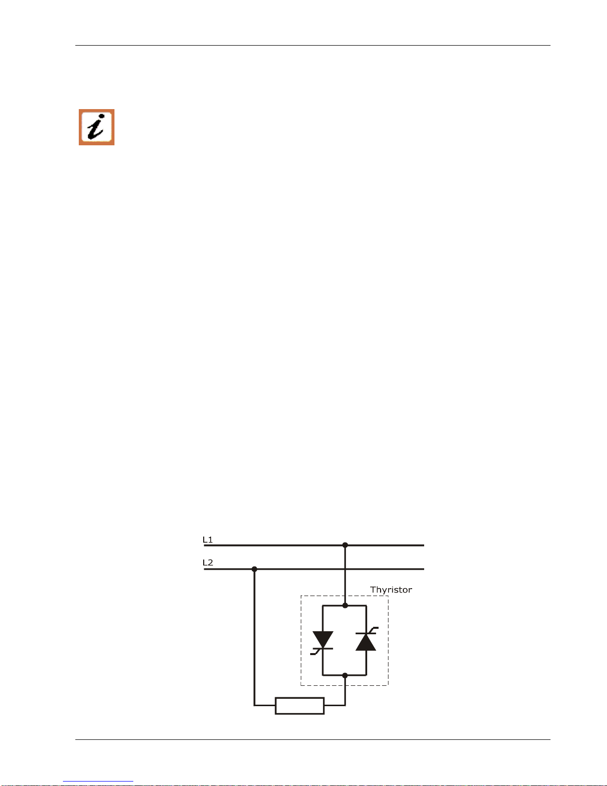
Thyristor units are used in power industrial equipment. When the thyristor unit is working, there
are on the unit the following voltages
- Maximum main supply voltage on power terminals up to 600V.
- Auxiliary supply 230-460Vac.
- Fan voltage 230Vac 50/60Hz Power consumption 14W.
Don't remove the plastic cover which provides adequate protection against electric shock.
Don’t use this thyristor in aerospace and nuclear application.
Electric Shock Hazard (Risque the choque électrique)
When thyristor unit has been connected to main supply voltage and is switched off, before to touch
it be secure that the unit is isolated and wait at least one minute to permit to discharge internal
capacitors. Thus be secure that:
• access to thyristor unit is only permitted to specialized personnel;
• the authorised personnel must read this manual before to have access to the unit;
• the access to the units must be denied to unauthorized personnel.
Important warnings(attention)
• Local regulations regarding electrical installation should be rigidly observed.
• Safety regulations must be rigidly observed.
• Don't bend components to maintain insulation distances.
• Protect the units from high temperature, humidity and vibrations.
• Don't touch components to prevent electrostatichal discharges on them.
• Verify that all ratings are in line with real needs.
• If authorized personnel must measure voltage, current etc. on units, take away rings and other
jewels from fingers and hands.
• Authorized personnel working on thyristor unit under power supply voltage must work on
insulated board. Be secure that board is not connected to earth.
This listing does not represent a complete enumeration of all necessary safety cautions.
www.honeywell.com/imc 2

User’s Manual CD3000M-2PH from 125A to 700A Honeywell
Protection(protection)
CD3000 thyristor family has a polymeric plastic cover in compliance to International specification
IP20. To understand if IP20 protection is sufficient should be evaluated the installation place where
the units are installed.
Open Type Equipment(équipment de type ouvert).
Maximum surrounding air temperature 40°C(Temperature de l’air environnante maximum 40°C).
Earth(terre)
CD3000 family has isolated heatsink. For safety connect the heatsink to earth to avoid shocks in
case that circuit board or thyristors lost insulation. Earth impedance should be correspondent to
local earth regulation. Periodically the earth efficiency should be inspected.
Electronic Supply(alimentation électronique)
CD3000 family electronic circuit should be supplied by dedicated voltage supply for all electronic
circuit but not in parallel with contactor's coil, solenoids and other inductive or capacitive loads. It's
recommended to use a shielded transformer.
Electromagnetic compatibility (compatibilité électromagnétique)
Our thyristor unit has an excellent immunity to electromagnetic interferences if all suggestions
contained in this manual are respected. In respect to a good Engineering practise, all inductive
loads like solenoids contactor coils should have a filter in parallel.
Emissions (emission)
All thyristor switching at high speed generate some radiofrequency disturbance. CD3000 serie
complies with EMC rules for CE mark. In many installations near electronic devices has not been
noted problems. If radiofrequency device at low frequency are used near the thyristor unit, some
precautions should be taken like line filters and shielded cables for input signal and for load cables.
CU
LISTED S
UL
®
NOTE
We reserves the right to apply modifications to the our products without any advice.
3 www.honeywell.com/imc

Honeywell CD3000M-2PH from 125A to 700A User’s Manual
1. Glossary
1.1 Terminology
V: voltage power supply.
I: the full circulating current in thyristor unit.
P: total load power.
1.2 Input signal
SSR: This input type is a square waveform generated by a temperature controller.
AN: Analog input.
IRS: Communication command.
1.3 Power feed back
Feedback: supply voltage fluctuation changes the power to the load. To overcome this effect
the voltage supplied to the load is measured and compared with power demand from
controller, the error signal is used to automatically hold the power at demanded level.
1.4 What is a thyristor unit
A thyristor unit is semiconductor device which acts as a switch formed by two thyristors in
antiparallel. To switch on the alternating current the input signal will be on and the thyristor will
switch off at first zero crossing voltage with no input signal. The benefits of thyristor units
compared with elettromechanical contactors are numerouses: no mooving parts, no maintenance
and capacity to switch very fast. Thyristors are the only solution to control transformers and
special loads that change resistance with temperature and with age.
LOAD
www.honeywell.com/imc 4

User’s Manual CD3000M-2PH from 125A to 700A Honeywell
2. Technical specifications
2.1 General Features:
Operating temperature 0÷45°C for higher temperature see derating curve
Voltage power supply 24 V minimum, 480V max and 600 V on request
Input signal SSR
4÷20 mA
0÷10V
potentiometer (10k ohm)
customer configurable with automatic zero/span calibration
Firing mode One of these firing modes can be configured on line via serial port
Zero Crossing (ZC)
Fast Cycle (FC)
Burst Firing (BF)
Auxiliary voltage supply 230 Æ200÷230V ±15%; 10 VA power consumption
460 Æ300÷460V ±15%; 10 VA power consumption
Fan voltage supply 230V ± 15 %;
110V ± 15 %; On request
Fuses Internal
Heather break alarm Discrimination better than 20%. Circuit microprocessor based to
diagnose partial or total load failure and short circuit on Thyristors.
Latching alarm plus reset. Relay output 0.5A at 125VAC
Line Drop Voltage Automatic compensation ±15% of supply voltage with analog input
Mounting Bulk head mounting
Protection IP20
2.2 Input features
Input signal Maximum
current drain Input
Impedance ON condition OFF condition
SSR 5mA constant current ≥4V-max 30V ≤1V
Analog 0-10V - 8200 ohm
Analog 4-20mA - 100 ohm
Potentiometer
10 K ohm 8200 ohm
5 www.honeywell.com/imc

Honeywell CD3000M-2PH from 125A to 700A User’s Manual
2.3 Output features
Current Voltage
range Ripetitive peak
reverse voltage Latching
current Max peak
one cycle Leakage
current I2T value
thyristor Frequency
range Power
loss Isolation
Voltage
(A) (V) (480V) (600V) (mAeff)
(10msec.)
(A) (mAeff) tp=10msec (Hz) I=Inom
(W) Vac
125 24÷500 1200 1600 450 2000 15 19100 47÷70 255 2500
150 24÷500 1200 1600 300 5250 15 128000 47÷70 268 2500
200 24÷500 1200 1600 300 5250 15 128000 47÷70 380 2500
275 24÷500 1200 1600 300 4800 15 108000 47÷70 623 2500
400 24÷500 1200 1600 200 7800 15 300000 47÷70 875 2500
450 24÷500 1200 1600 200 7800 15 300000 47÷70 1021 2500
500 24÷500 1200 1600 200 8000 15 306000 47÷70 1061 2500
600 24÷500 1200 1600 1000 17800 15 1027000 47÷70 1178 2500
700 24÷500 1200 1600 1000 17800 15 1027000 47÷70 1425 2500
2.4 Derating curve
1
0.8
0.6
0.4
0.2
045 55 65 75 85
K
°C
I = I x K
NOMMAX
2.5 Fans
The thyristor units are equiped with a fan. The fan supply must be protected with a fuse.
Fan voltage supply is standard 230VAC ±15% 50/60Hz or optional 110VAC ±15% 50/60Hz.
The power consumption is given in the table below.
Size Number of fans UL Number of fans
125A, 150A, 200A One Fan - 14W One Fan - 14W
275A, 450A, 700A Four Fan - 60W Four Fan - 60W
400A, 500A, 600A Two Fans - 30W Four Fan - 60W
www.honeywell.com/imc 6

User’s Manual CD3000M-2PH from 125A to 700A Honeywell
3.Ordering information
Model CD3000M 2PH
1 2 3 4 5 6 7
CD3000M-2PH
Ex:CD3000M 2PH/ 150A
/ 400V
/ 480V
/ 460V
/ SSR/ ZC/ UL
1 Nominal current of CD3000M
125A 275A 500A
150A 400A 600A
200A 450A 700A
2 Operating Load Voltage (incoming voltage supply)
Specify the value of the line supply.
3 Max VOLTAGE of CD3000M
480V
600V
The voltage on the identification label must be equal or more than
operating voltage. The minimum voltage supply to the load is 24V.
4 Auxiliary Voltage
230V 200÷230V ±15%; 10VA
460V 300÷460V ±15%; 10VA
600V 600V ±15%; 10VA (on request)
5 Input
SSR 4÷30VDC
0-10V 0÷10V analog input
4-20mA 4÷20mA analog input
10K pot Potentiometer
6 Firing
ZC Zero Crossing
BF Burst firing. Specify the number on ON cycles at 50% of
power.
7 Options
COMM MODBUS protocol in RS485 is standard
CD-KP External Keypad
HB Heater Break Alarm
FAN110 Fan voltage supply 110VAC ±15% (std 230VAC ±15%)
14W 50/60Hz
UL UL Certification
7 www.honeywell.com/imc

Honeywell CD3000M-2PH from 125A to 700A User’s Manual
4. Installation and wiring information
4.1 Identification of the unit
Before to install the CD3000M unit examine for damages or deficiencies. If any is
found, notify the carrier immediately. Check that the product features shown on
CD3000M identification label corresponds to that ordered.
An identification label provide all the informations regarding the factory settings of the unit. This
label is on the board inside the unit, as represented below:
Identification Label
FIRING FIR.OPT
AMPS SUPPLY
INPUT
4.2 Installation
CD3000M unit should be always mounted in vertical position to improve air cooling on
heatsink. Maintain minimum distances in vertical and in horizontal as below
represented. Don’t install in proximity of hot elements and near units generating
electromagnetic interferences.
When more units are mounted inside a cubicle provide air circulation as below represented.
Sometimes it is necessary to provide a fan to have better air circulation.
www.honeywell.com/imc 8

User’s Manual CD3000M-2PH from 125A to 700A Honeywell
4.3 Dimensions
Size W(mm) H(mm) D(mm)
125A (S9) 116 316 187
150A (S9) 116 316 187
200A (S10) 116 350 220
275A (S14) 262 520 270
400A (S14) 262 520 270
450A (S14) 262 520 270
500A (S14) 262 520 270
600A (S14) 262 520 270
700A (S14) 262 520 270
9 www.honeywell.com/imc

Honeywell CD3000M-2PH from 125A to 700A User’s Manual
4.4 Fixing Holes
A
B
C
Size A(mm) B(mm) C(mm)
125A (S9) 96 290 104
150A (S9) 96 290 104
200A (S10) 100 335 100
275A (S14) 222 495 222
400A (S14) 222 495 222
450A (S14) 222 495 222
500A (S14) 222 495 222
600A (S14) 222 495 222
700A (S14) 222 495 222
www.honeywell.com/imc 10

User’s Manual CD3000M-2PH from 125A to 700A Honeywell
5. Wiring Instructions
5.1 Removing the cover
To open the unit apply as follow.
For S9 and S10 sizes, you must open the cover to configure the unit and to view the fuses
For S14 size, you must open the cover to cable, to configure the unit and to view the fuses
Warning: this procedure can be done just by specialized personnel
CD3000M unit has isolated heatsink. For safety connect the heatsink to hearth using
its terminal with hearth symbol.
CD3000M can be susceptible to airborne interferences from near equipment or from interferences
on main supply, so a number of precautions must be taken.
• Contactors coils and chokes must have in parallel a RC filter and must be supplied with a
different voltage line.
• All input/output signal must use screened bifilar wires.
• Signal input and output must not routing in same cable try and must not be parallel.
• Local regulations regarding electrical installation should be rigidly observed.
11 www.honeywell.com/imc

Honeywell CD3000M-2PH from 125A to 700A User’s Manual
5.1.1 Auxiliary Terminals
Before connect or disconnect, make sure that the power, control cables and wires are
insulated from the voltage.
Terminal Description
1 Auxiliary supply voltage 230-460Vac (600V on request)
2 N.C. not connected
3 Auxiliary supply voltage 230-460Vac (600V on request)
4 N.C. not connected
5 Fan supply 240V (if mounted)
6 Fan supply 240V (if mounted)
7 Reset
8 Reset
9 + Input command signal 4÷20mA, 0÷10V, SSR
10 - Input command signal 4÷20mA, 0÷10V, SSR
11 ∅Volt GND
12 Output + 8Vdc stabilized, 1mA max
13 + Output command signal to CD3000 slave
14 - Output command signal to CD3000 slave
15 + External HB Calibration command 24Vdc max
16 - External HB Calibration command 24Vdc max
17 Used for the future
18 NOHB relay alarm ** (coil not energized)
19 Common relay HB alarm
20 NCHB relay alarm ** (coil not energized)
** In alarm condition or withoutauxiliary voltage the coil is not energized. In normal condition
(no alarm) the coil is energized.
Auxiliary terminals
www.honeywell.com/imc 12

User’s Manual CD3000M-2PH from 125A to 700A Honeywell
5.1.2 Power Terminals
Before connect or disconnect, make sure that the power, control cables and wires are
insulated from the voltage.
Terminal Description
L1 Line Input Phase 1
T1 Load Output Phase 1 – controlled by the thyristor
L2 Line Input Phase 2
T2 Load Output Phase 2 – NOT controlled by the thyristor
L3 Line Input Phase 3
T3 Load Output Phase 3 – controlled by the thyristor
L1 L2 L3
T
1 T2 T3
13 www.honeywell.com/imc

Honeywell CD3000M-2PH from 125A to 700A User’s Manual
5.2 Cabling detail
Use 75°C copper (CU) conductor only, provided with the terminal type indicated below.
Current/courant Torque/couple
Lb-in (N-m) Wire
Range/cable Wire
Terminal/terminal
125A, 150A,
200A, 225A 310 (35.0) Polymeric Terminal
Block M8
275A 372 (42.0) Bus Bar Adapter M8
400A
18 - 600kcmil
450A, 500A
600A, 700A
505 (57.0) Bus Bar Bus Bar Adapter M10
www.honeywell.com/imc 14

User’s Manual CD3000M-2PH from 125A to 700A Honeywell
Power terminals: wire details:
Current Supply
L1, L2 and L3 Load
T1, T2 and T3
Cable Cable
mm2AWG
Screw
M mm2AWG
Screw
M
125A 50 1 M8 50 1 M8
150A 70 1/0 M8 70 1/0 M8
200A 95 3/0 M8 95 3/0 M8
225A 120 4/0 M8 120 4/0 M8
275A 2 x 70 2 x 1/0 M8 2 x 70 2 x 1/0 M8
400A 2 x 95 2 x 3/0 M10 2 x 95 2 x 3/0 M10
450A Bus Bar 30 x 6 mm Bus Bar 30 x 6 mm
500A Bus Bar 60 x 4 mm Bus Bar 60 x 4 mm
600A Bus Bar 60 x 5 mm Bus Bar 60 x 5 mm
700A Bus Bar 60 x 6 mm Bus Bar 60 x 6 mm
Auxiliary connectors and earth:
Current Auxiliary Supply Earth
Cable
Cable
mm2AWG
mm2AWG
Screw
M
125A 0,50 18 16 6 M6
150A 0,50 18 16 6 M6
200A 0,50 18 25 4 M8
225A 0,50 18 35 2 M8
275A 0,50 18 50 1 M8
400A 0,50 18 50 1 M8
450A 0,50 18 70 1/0 M8
500A 0,50 18 70 1/0 M8
600A 0,50 18 70 1/0 M8
700A 0,50 18 70 1/0 M8
15 www.honeywell.com/imc

Honeywell CD3000M-2PH from 125A to 700A User’s Manual
5.2.1 Serial Communication Terminals
5
16
9
www.honeywell.com/imc 16
Pin 1 PMS5 (+5V)
Pin 2 GND 0V
Pin 3 GND 0V
Pin 4 Reserved (Rxd0)
Pin 5 GND 0V
Pin 6 RS485 A
Pin 7 RS485 B
Pin 8 nc
Pin 9 Reserved (Txd0)
B
RS485
A

User’s Manual CD3000M-2PH from 125A to 700A Honeywell
5.3 Wiring connection
5.3.1 CD3000 125-700A
RESET 7
RESET 8
INPUT + 9
INPUT - 10
0V GND 11
+ 8V 12
SLAVE + 13
SLAVE - 14
+ CAL 15
- CAL 16
17
N.C. 18
L2
L3
L3
L2L1
T3T2T1
L1
Star Load
460/230V 3
PE 4
FAN 5
FAN 6
460/230V 1
2
COM 19
N.O. 20
FAN SUPPLY 230V Std
HB RELAY OUTPUT
INPUT SIGNAL
SSR/Volt/mA
EXTERNAL HB
CALIBRATION 24 V dc
INPUT
POT 10 Kohm
**
NOTE: IMPORTANT
* The user installation must be protected by electromagnetic circuit breaker or by
fuse isalator.
The auxiliary voltage supply must be connected as above, and must be syncronized
with load voltage power supply (L1, L2).
** If the auxiliary voltage (written on the identification label) is different from supply voltage (to
the load), use an external transformer, as reported above.
To work terminals 7-8 must be linked.
Fan voltage supply is standard 230VAC ±15% 50/60Hz or optional 110VAC ±15% 50/60Hz. For
power consumption see fan paragraph.
17 www.honeywell.com/imc
Table of contents
Other Honeywell Semiconductor manuals