J. H. • 7-92 • © Honeywell Inc. 1992 • Form Number 69-0726
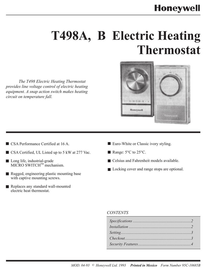
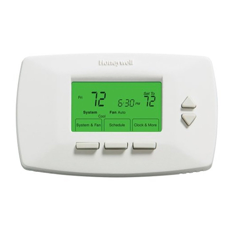
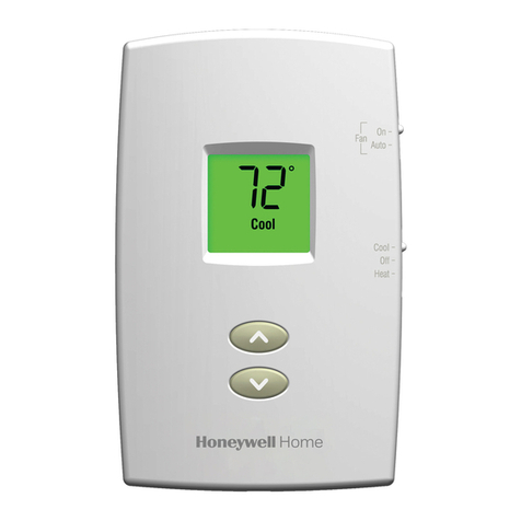
VVT, VVT-HC (T641A,C)
Floating Control Thermostats
Installation Instructions for the Trained Service Technician.
Application
TheVVTandVVT-HCThermostatsprovidespdtoutputs
to control floating actuators in applications such as variable
air volume (VAV) terminal units.
—VVT (T641A): standard spdt floating control
thermostat.
—VVT-HC (T641C): provides manual heat/cool
changeover switch.
Operation
FLOATING CONTROL
The control provided by the thermostat is conventionally
calledfloatingcontrol.Duringfloatingcontrol, avariationof
two-position control, the thermostat provides a three output
control, which is Advance motor, Reverse motor, and Hold.
On a change in temperature, the thermostat drives the
actuatorto an intermediateposition and thenopens the circuit
to the actuator. The actuator remains in this position until
there is a temperature change at the thermostat. The actuator
is said to float between the limits of the thermostat to satisfy
various load requirements.
VAV SYSTEMS
VAV systems control the temperature within a space by
varying the volume of supply air. Air is delivered to the space
at a fixed temperature. The volume of supply air is controlled
by the space thermostat modulating the supply air damper.
Whenfullheatingandcoolingflexibilityisrequiredinazone,
it is handled by perimeter heating, or reheat capability in the
air terminal units. As individual zones shut down, the total air
flowinthesystemisregulatedbyacentralductstaticpressure
controller. The fan system is sized to handle an average peak
load, not the sum of the individual peaks. Because each zone
peaksat a different time ofday, extraair is borrowed from the
off-peak zones. This transfer from low-load to high-load
zones occurs only in true VAV systems.
Pressure dependent systems do not incorporate an indi-
vidual zone air flow sensor and depend on a stable system
pressure to maintain flow. These systems require slower
motorssuchasthesevenminutedampers,whicharetypically
controlled by the VVT (T641A) or VVT-HC (T641C) Ther-
mostats.
HEAT ANTICIPATION/COOL ANTICIPATION
Control of heating or cooling units with a thermostat does
notallow forthe temperatureto remainexactly atthe thermo-
stat set point, but varies within a certain temperature range.
Anticipation is added to the thermostat to reduce
this range.
The anticipator is a small resistive heater in the thermostat
that heats when the system is on or off. The heat produced by
theanticipatorraisestheinternalbimetaltemperatureslightly
faster than the surrounding room temperature. The thermo-
stat anticipates the need to shut off the heating system sooner
thanit would if affected byroom temperature only. The VVT
(T641A) or VVT-HC (T641C) have fixed or voltage antici-
pation.
Installation
WHEN INSTALLING THIS PRODUCT…
1. Read these instructions carefully. Failure to follow
them could cause a hazardous condition.
2. Check the ratings given in the instructions and on
the product to make sure the product is suitable for your
application.
3. Installer must be a trained experienced service
technician.
4. After installation is complete, check out product op-
eration as provided in these instructions.
CAUTION
1. Disconnect power supply to prevent electrical
shock or equipment damage.
2. Topreventinterferencewiththethermostatlink-
age, keep wire length to a minimum and run
wires as close as possible to the subbase.
3. Donotovertightenthermostatcaptive mounting
screws, because damage to subbase threads can
result.
4. Do not short across coil terminals on relay. This
can burn out the thermostat heat
anticipator.
IMPORTANT:Anincorrectlyleveledthermostatwill cause
the temperature control to deviate from set point. It is
not a calibration problem.
!
