TABLE OF CONTENTS
8024GPS - GPS Sync Module - V02.00 5 / 76
hopf
Elektronik GmbH
Nottebohmstr. 41
•
D-58511 Lüdenscheid
•
Tel.: +49 (0)2351 9386-86
•
Fax: +49 (0)2351 9386-93
•
Internet: http://www.hopf.com
•
E-Mail: info@hopf.com
Contents Page
1General..........................................................................................................................7
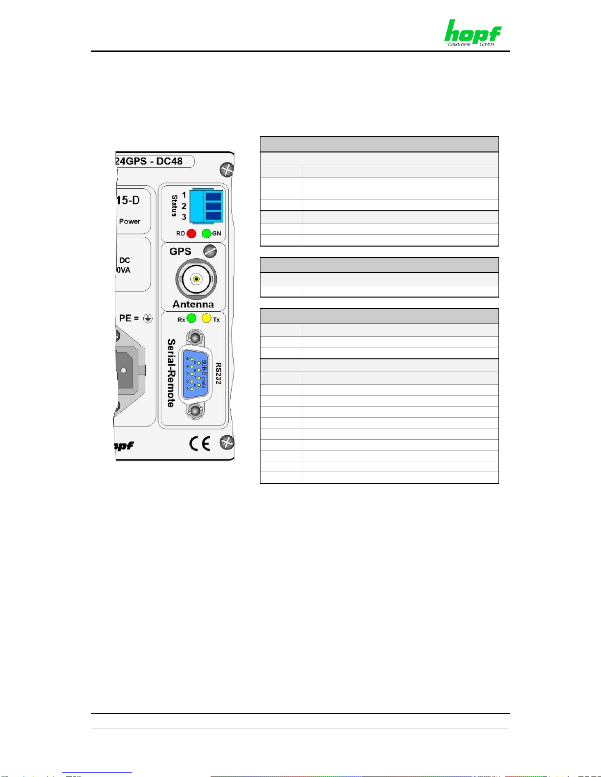
2Hardware.......................................................................................................................8
2.1 Example: Front Panel for DIN Rail Mounting.............................................................................8
2.2 Front Panel Connections............................................................................................................8
2.2.1 GPS Antenna Connection.....................................................................................................8
2.2.2 Status LEDs..........................................................................................................................9
2.2.3 Status Optical Coupler..........................................................................................................9
2.2.4 Serial-Remote Interface for
hmc
software...........................................................................9
2.3 Back-up Clock............................................................................................................................9
2.4 Voltage Feed..............................................................................................................................9
2.5 Further Signal Outputs...............................................................................................................9
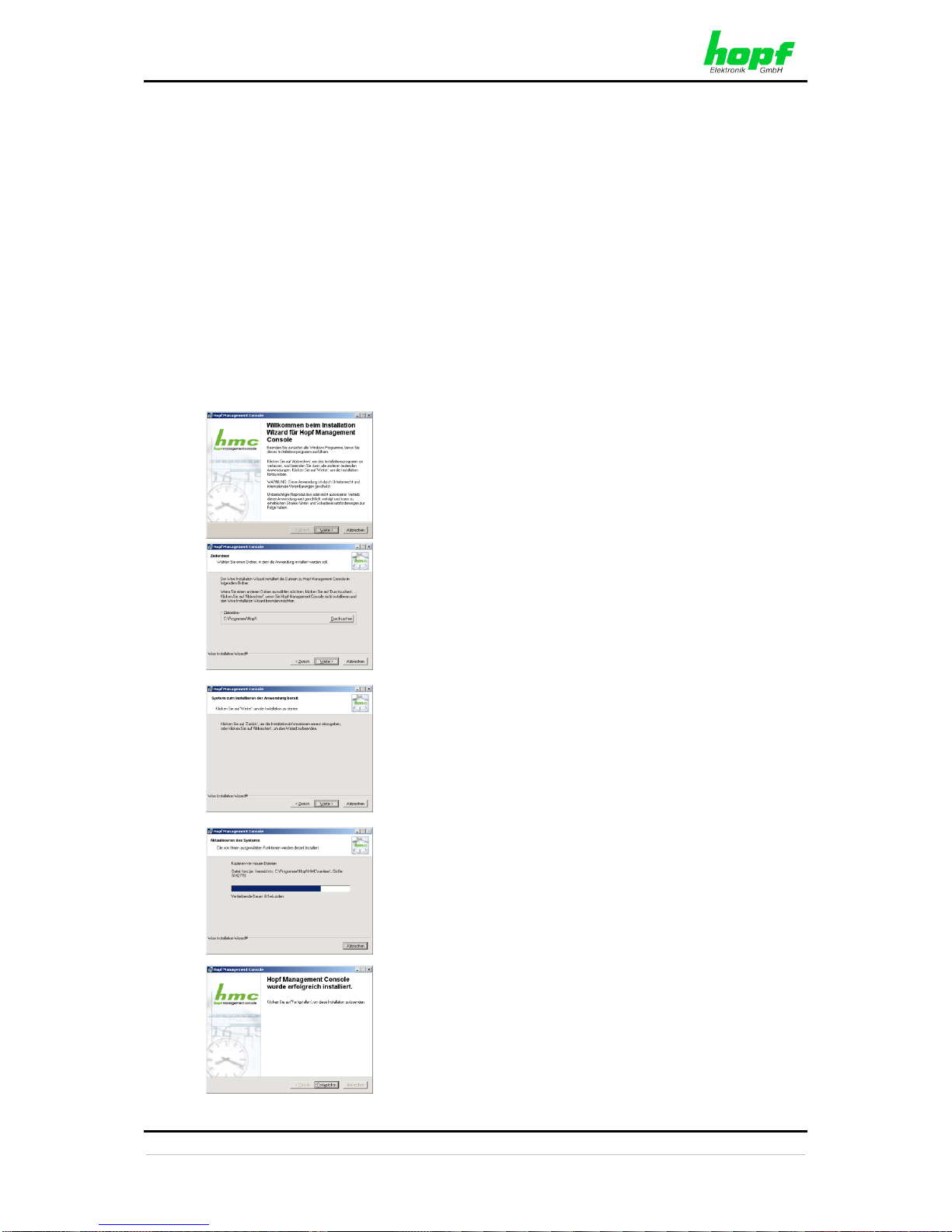
3
hmc
(
hopf
Management Console) software ...........................................................10
3.1 Installation on Microsoft Windows........................................................................................... 10
3.2 Starting the
hopf
Management Console software ................................................................ 11
3.3 The Control Elements ............................................................................................................. 11
3.3.1 The Menu - Area A............................................................................................................. 12
3.3.2 The Tool Bar - Area B........................................................................................................ 13
3.3.3 The Device Tree - Area C.................................................................................................. 13
3.3.4 The Main Area - Area D..................................................................................................... 14
3.3.5 The Status Bar - Area E..................................................................................................... 14
3.4 Create a serial-remote Connection to
hmc
software............................................................. 15
3.5 Operation / Display.................................................................................................................. 17
3.5.1 Configuration / Plausibility Check ...................................................................................... 18
3.5.2 Transmit Value Changes ................................................................................................... 18
3.5.3 Read from Device .............................................................................................................. 18
3.5.4 Undo All Changes.............................................................................................................. 19
3.5.5 Load a Configuration File................................................................................................... 19
3.5.6 Save the Current Configuration ......................................................................................... 19
3.6 Description of the Tabs ........................................................................................................... 20
3.6.1 Time and date –Tab.......................................................................................................... 20
3.6.1.1 Time panel 21
3.6.1.2 Setting Date and Time 22
3.6.1.3 Daylight Saving panel 23
3.6.1.4 Time Zone Selection (Time Zone Offset) panel 24
3.6.2 System –Tab..................................................................................................................... 26
3.6.2.1 SyncON / SyncOFF 26
3.6.2.2 Reset 27
3.6.3 GPS –Tab ......................................................................................................................... 28
3.6.4 Output –Tab...................................................................................................................... 29
3.6.4.1 PPS - optional hardware necessary 30
3.6.4.1.1 PPS duration 30
3.6.4.1.2 Minimum Sync.-Status - Status-Dependent Pulse Output 30
3.6.4.1.3 Status of the Signal Output 31
3.6.4.1.4 Output inverted –Polarity of the output Pulse 31
3.6.4.1.5 Special Configuration 31
3.6.4.2 DCF77 - optional hardware necessary 32
3.6.4.2.1 Time Base of the Transmitted DCF77 Pulse 32