iStartek VT600 3G User manual

File Name:
VT600-3G User Manu
al
Version
1.1
Project:
VT600-3G
Update Date:
2015-4-15
Sub Project:
User Manual
Page:
1 of 21
GPS Vehicle Tracker
User Guide V1.1
VT600-3G

File Name:
VT600-3G User Manu
al
Version
1.1
Project:
VT600-3G
Update Date:
2015-4-15
Sub Project:
User Manual
Page:
2 of 21
Contents
1. Poduct Overview........................................................................................................................... 3
2. For Your Safety............................................................................................................................. 3
3. VT600-3G Characteristics ................................................................................................................ 4
4. Getting Started.............................................................................................................................. 4
4.1 Hardware andAccessories...................................................................................................... 4
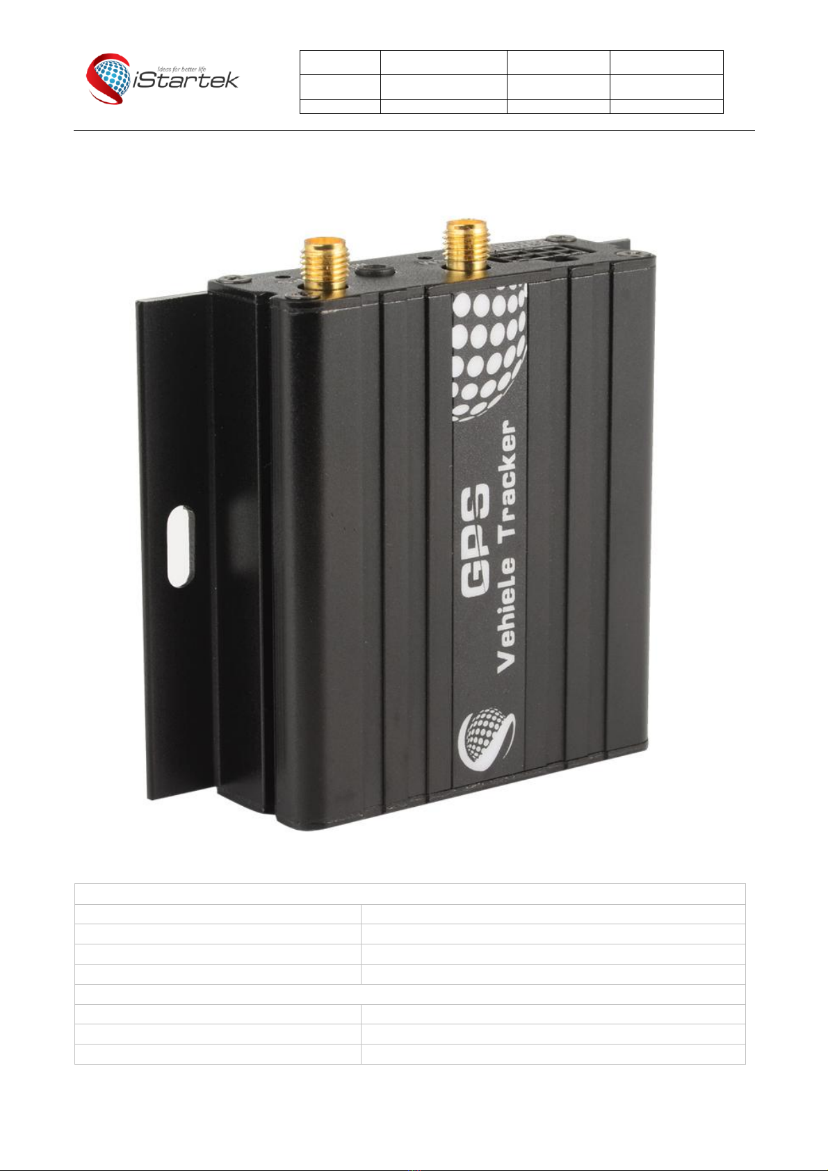
4.2 View ................................................................................................................................. 5
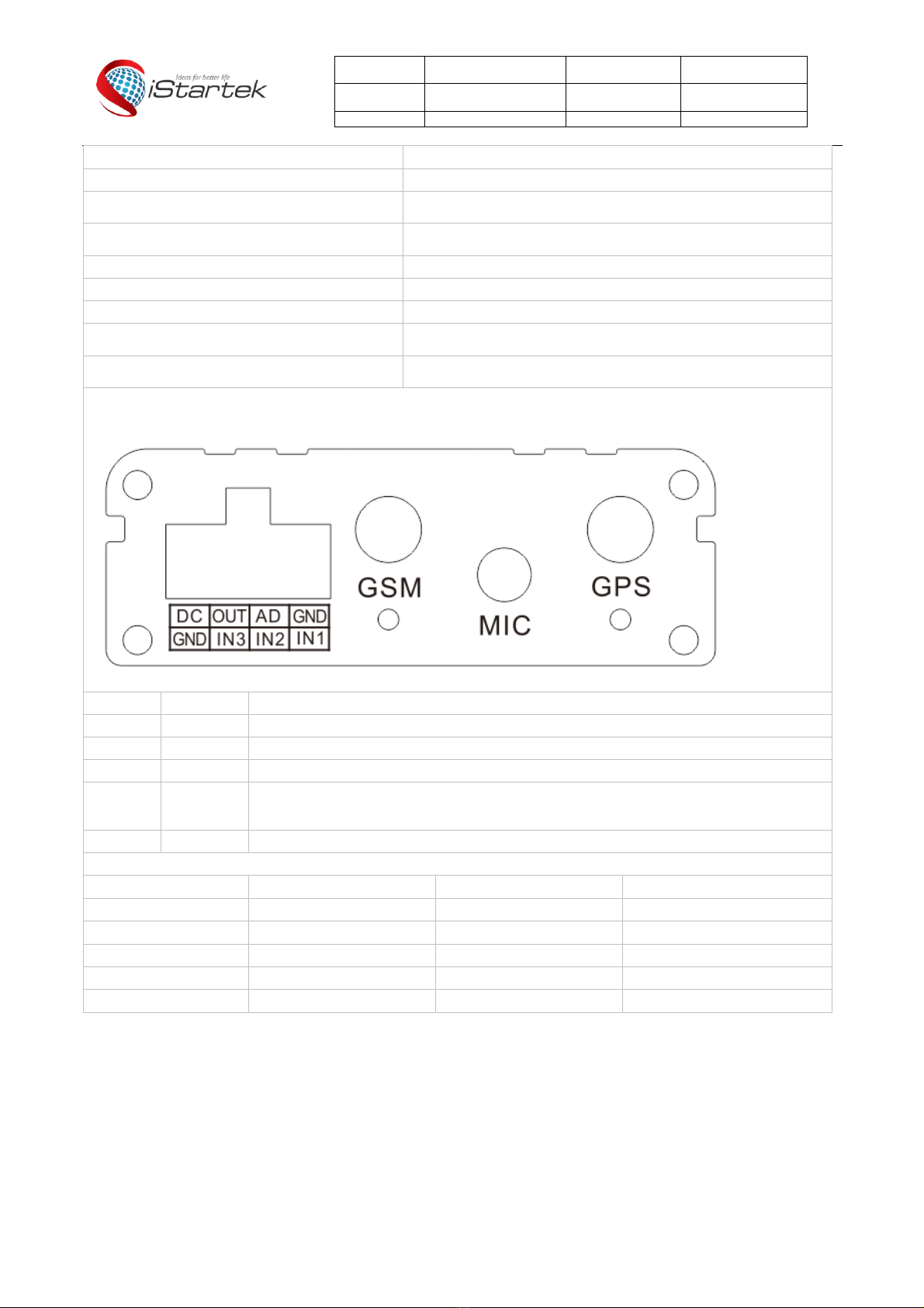
4.3 Functional Parts ................................................................................................................... 5
4.4 Connecting and Installation...................................................................................................... 6
5. Change Password.......................................................................................................................... 7
6. Time Zone ................................................................................................................................... 7
7. Track.......................................................................................................................................... 7
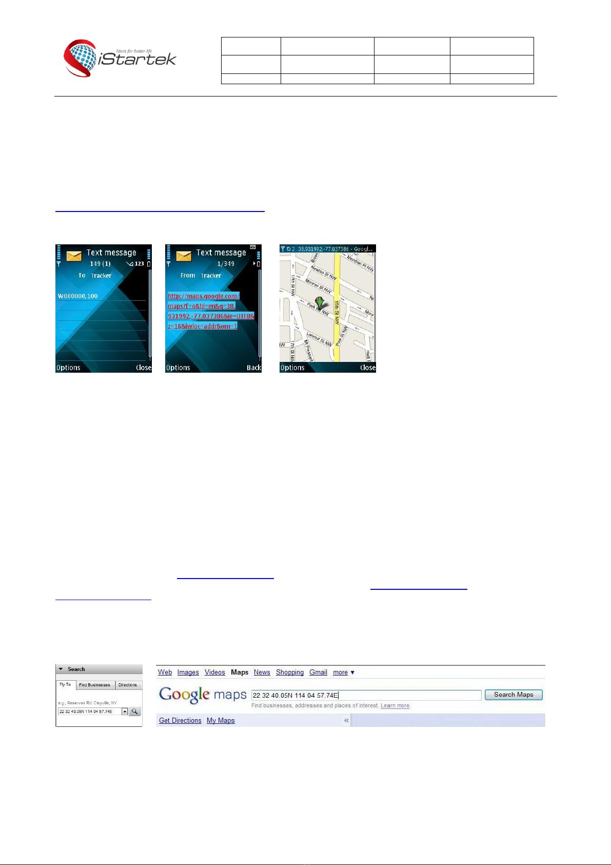
7.1 Track by SMS...................................................................................................................... 7
7.2 Track by Calling ................................................................................................................... 8
7.3 Track by Preset Interval.......................................................................................................... 8
7.4 Google Earth and Google Map ................................................................................................. 8
7.5 Track by GPRS between Server and Tracker.............................................................................. 9
7.5.1 Set Tracker’s GPRS ID...................................................................................................9
7.5.2 SetAPN.....................................................................................................................9
7.5.3 Set IP and Port.............................................................................................................9
7.5.4 Set DNS Server IP (optional)............................................................................................9
7.5.5 Enable GPRS Tracking...................................................................................................9
7.5.6 Set GPRS Interval.........................................................................................................9
7.5.7 Set ACC Off Interval ....................................................................................................10
7.5.8 Set ACC Off Interval Function.........................................................................................10
8. Authorization ........................................................................................................................... 10
9. Application Examples for Inputs ....................................................................................................... 10
9.1 SOS Button Connection........................................................................................................ 10
9.2 Detecting Lock Status of Car’s Door or Trunk (Car Boot). ............................................................... 11
9.3 Connecting with Switch Sensors ............................................................................................. 11
9.4 Ignition Detection................................................................................................................ 11
9.5 Analog Input (AD1).............................................................................................................. 11
10. Speeding Alarm ......................................................................................................................... 12
11. Movement/Geo-fence.................................................................................................................. 12
11.1 MovementAlarm............................................................................................................... 12
11.2 Geo-fence Alarm............................................................................................................... 13
12. Track by Distance....................................................................................................................... 13
13. Listening-in (Optional) ................................................................................................................. 13
14. Set Sensitivity of Tremble Sensor.................................................................................................... 13
15. Output Control........................................................................................................................... 14
15.1 Output Control (Immediate).................................................................................................. 14
15.2 Output Control (Conditional)................................................................................................. 14
15.3 Application Examples for Outputs........................................................................................... 14
15.3.1 Engine Cut .............................................................................................................. 14
15.3.2 Connecting with Car Alarm........................................................................................... 15
16. Heading Change Report............................................................................................................... 15
17. Heartbeat................................................................................................................................. 15
18. Track Log................................................................................................................................. 15
18.1 Log by Interval ................................................................................................................. 15
18.2 Auto Log when no GPRS..................................................................................................... 16
18.3 Format Buffer................................................................................................................... 16
19. Power Down............................................................................................................................. 16
20. Get IMEI.................................................................................................................................. 16
21. Initialization .............................................................................................................................. 16
22. Password Initialization ................................................................................................................. 16
Annex 1. SMS Command List............................................................................................................. 16
Annex 2. Troubleshooting.................................................................................................................. 21

File Name:
VT600-3G User Manu
al
Version
1.1
Project:
VT600-3G
Update Date:
2015-4-15
Sub Project:
User Manual
Page:
3 of 21
1. Poduct Overview
VT600-3G is a GPS/GPRS based tracking device, specially developed and designed for vehicle real-time tracking and fleet
management.
VT600-3G has an inbuilt GPS module to obtain accurate position data. This device utilizes its GSM capability to send
position data to a specified mobile phone or server base for tracking and fleet management.
With internal memory, VT600-3G can store GPS coordinates when there is no GPRS connection, or ata specified interval
requested by the user.
One optional feature of VT600-3G is that a microphone can be linked and hidden somewhere inside the vehicle for listening
to the cabin.
VT600-3G has the following functions and features:
SMS and GPRS TCP/UDP Communication
AGPS ( with GSM Base Station ID)
Track on Demand
Show Location Directly on Mobile Phone
Track by Time Interval
Track by Distance
Listen-in (optional)
Anti-Jammer (optional)
GSM Blind Area Memory
Internal Memory for Logging
Inbuilt Motion Sensor for Power Saving
SOS Panic Button
Movement Alarm
Geo-fencing Control
LowBattery Alarm
Speeding Alarm
GPS Blind Area Alarm (in/out)
Power-cut Alarm
Engine Cut (Stop Engine)
I/O: 3 digital inputs , 1 outputs and 1 analog inputs of 10 bits resolution
2. For Your Safety
Read these simple guidelines. Not following them may be dangerous or illegal.
Proper Connection
Do not connect any parts of this product to other incompatible devices. When
connecting with other devices, read instructions carefully to ensure proper
installation.
Qualified Accessories
Use original parts, qualified batteries and peripheral equipments to avoid
damage to VT600-3G.
Safe Driving
Drivers should not operate this product while driving.
Qualified Service
Only qualified personnel can install or repair VT600-3G.
Water Resistance
VT600-3G is not water resistant. Keep it dry. Installthis device inside the vehicle
or use a waterproof bag for protection if necessary.
Confidential Phone Number
For safety reason, do not tellother people the mobile phone number of your
VT600-3G without taking precautions of security settings.

File Name:
VT600-3G User Manu
al
Version
1.1
Project:
VT600-3G
Update Date:
2015-4-15
Sub Project:
User Manual
Page:
4 of 21
3. VT600-3G Characteristics
Items
Specifications
Power Supply
10.6V - 36V / 1.5A
Backup Battery
500mAh
Normal power consumption
55mA/h
Dimension
65 x 61 x 26mm
Weight
90g
Work time
30 hours in power-saving mode and 7.5 hours in normal mode
Operating temperature
-20°to 55°C
Humidity
5% to 95%Non-condensing
Frequency
VT600-3G-T
UMTS/HSDPA: 850/2100MHz GSM/GPRS: 850/900/1800/1900MHz
VT600-3G-A
UMTS/HSDPA: 850/1900MHz GSM/GPRS: 850/900/1800/1900MHz
VT600-3G-E
UMTS/HSDPA: 900/2100MHz GSM/GPRS: 900/1800MHz
GPS Module
latest GPS SIRF-Star IV chipset
GPS Sensitivity
-163Db
GPS Frequency
L1, 1575.42 MHz
C/A Code
1.023 MHzchip rate
Channels
48 channel all-in-view tracking
Position Accuracy
10 meters, 2D RMS
Velocity Accuracy
0.1 m/s
Time Accuracy
1 us synchronized to GPS time
Default datum
WGS-84
Reacquisition
0.1 sec., average
Hot start
1 sec., average
Warm start
35 sec., average
Cold start
35 sec., average
Altitude Limit
18,000 meters (60,000 feet) max
Velocity Limit
515 meters/second (1000 knots) max
LED
2 LED lights to showGPS/GSM status
Flash Memory
8MB
Button
One SOS Button
Interface
3 digital inputs (2 negative and1 positive triggering)
1 analog inputs
1 outputs.
4. Getting Started
This section will describe howto set up your VT600-3G.
4.1 Hardware and Accessories
VT600-3G is supplied in a box which includes:
VT600-3G with battery, GPS antenna, GSM antenna, Wires with SOS button

File Name:
VT600-3G User Manu
al
Version
1.1
Project:
VT600-3G
Update Date:
2015-4-15
Sub Project:
User Manual
Page:
5 of 21
4.2 View
4.3 Functional Parts
GPS LED (Blue)
On
One button is pressed or input is active
Flashing ( every 0.1 second)
The unit is being initialized
Flashing (0.1 second on and 2.9 seconds off)
VT600-3G has a GPSfix
Flashing (1 second on and 2 seconds off)
VT600-3G has no GPS fix
GSM LED (Green)
On
A call is coming in / a call is being made
Flashing ( every 0.1 second)
The unit is being initialized
Flashing (0.1 second on and 2.9 seconds off)
VT600-3G is connected to the GSM network

File Name:
VT600-3G User Manu
al
Version
1.1
Project:
VT600-3G
Update Date:
2015-4-15
Sub Project:
User Manual
Page:
6 of 21
Flashing (1 second on and 2 seconds off)
VT600-3G is not connected to the GSM network
Power On/Off Button
Press and hold for 3~5 seconds to turn on/off VT600-3G
SOS Button
SOS button is connected with the wires. Press it to send SOS
alarm to the preauthorized phone number.
Mini USB
Used for firmware update, configuration on PC and exporting
stored data.
SIM Card Holder
Insert SIM card here
GSM Antenna
Connector for GSM antenna
GPS Antenna
Connector for GPS antenna
Screw Holes
There are 4 screwholes on the tracker, 2 along either side that act
as fixing points to the vehicle
Microphone (optional)
A microphone to be linked out for listening to the cabin
(wiretapping)
PINs Connector
PIN
Color
Function
Power
Red
DC In (power input). Input voltage: 10.6V~36V. 12V suggested
GND
Black
Ground
In
White
DigitalInputs. In1, In2 are negative triggering; In3 is positive triggering
Out
Yellow
Outputs. Lowvoltage (0V) when effective and open drain when ineffective
Output open drain sinkvoltage (ineffective): 45V max.
Output lowvoltage sink current (effective): 500mA max.
AD
Blue
10 Bits Resolution Analog Inputs. Input voltage: 0~6V
DC Characteristics of PINs
PIN
Inactive
Active
Maximum
Input 1/2
Open drain or >1V
0V(GND)
45V
Input 3
Open drain or 0V(GND)
>3V
45V
Output 1
Open drain
0V (GND)
45V/500mA
DC IN
/
9-36V
45V
AD 1
/
0-6V
45V
4.4 Connecting and Installation
Read this manual before using your VT600-3G. Check to make sure all parts are included in the packaging box.
4.4.1 Ensure that your VT600-3G has a working SIM card installed.
- Check that the SIMcard has not run out of credit (test the SIMcard ina phone to make sure it
can send and receive SMS)
- Check that the SIM card lock code is turned off
- If you require the function of sending an SMS location report to the authorized phone number
when it makes a callto the VT600-3G, please make sure the SIM installed supports displaying
caller ID.

File Name:
VT600-3G User Manu
al
Version
1.1
Project:
VT600-3G
Update Date:
2015-4-15
Sub Project:
User Manual
Page:
7 of 21
Before inserting SIM card, cut off the power for VT600-3G.
Install SIM Card
- Unscrew and remove the front cover of VT600-3G.
- Insert the SIM card by sliding it into the card slot with the chip module facing the connectors
on PCB.
- Replace the front cover andscrewit in.
4.4.2 Antenna Connection
Connect the GSM Antenna to VT600-3G.
Connect the GPS Antenna to VT600-3G.
- GPSantenna is used to receive satellite signals in the sky. It should be fixed to face the sky, (It
is recommended to place this device under the windshield) andshould not be covered or
shielded by any objects containing metal.
4.4.3 Find a suitable place inside the car for installing VT600-3G. Wiring connections must be
firmandreliable. The joints should be wrappedtightly withinsulating tape. The unusedelectrical
wire should be properly insulated.
Check to make sure all wirings have been connected correctly. Then connect the AVL unit to
the motor power.
Make a missed phone call the VT600-3G usinga mobile phone to check if the call can go
through.The VT600-3G should reply with an SMSindicating longitude, latitude, speedand date.
5. Change Password
Command:W******,001,######
Description: Change user’s password.
Note:
1. ****** is user’s password and the default password is 000000. The tracker will only accept commands from a user with
the correct password. Commands with wrong password will be ignored.
2. ###### is the newpassword. Password should be 6 digits.
Example:
W000000,001,123456
W123456,001,999999
6. Time Zone
Command:W******,032,T
Description: Correct time to your local time
Note:
1. Default time of the tracker is GMT
2. This correction is applied to location reports by SMS and SMS alarms.
T=0, to turn off this function;
T=[-720,720] to set time difference in minutes to GMT.
For those aheadof GMT, input the time difference in minutes directly.
For example, for GMT+8,W000000,032,480. (8 Hours is 480 minutes)
‘-‘is required for those behind GMT.
For example, W000000,032,-120. (2 hours or 120 minutes behind GMT)
Example:
W000000,032,480
W000000,032,-120
7. Track
7.1 Track bySMS
- Track on Demand - Reply with longitude, latitude, speed and date
Command:W******,000

File Name:
VT600-3G User Manu
al
Version
1.1
Project:
VT600-3G
Update Date:
2015-4-15
Sub Project:
User Manual
Page:
8 of 21
Description: To get the current location of the tracker, send this commandas an SMS or make a telephone call directly to
the tracker. After doing so, the device will report its longitude and latitude by SMS with the format as follows:
Latitude = 22 32 36.63N Longitude = 114 04 57.37E, Speed = 40.5Km/h, 2011-12-24,01:50
Example:
W000000,000
- Track on Demand - Replywith a link to Google Maps
Command:W******,100
Description: Send this command to the tracker and you willreceive an SMS with an http link. Click on the link and the
location will be shown directly on your mobile phone using Google maps. For example:
http://maps.google.com/?q=22.540103,114.082329
Note: Only smart phones and PDAs support this function.
Example:
W000000,100
7.2 Track byCalling
Make a missed call to the tracker andit will report its longitude and latitude by SMS with the following format:
Latitude = 22 32 36.63N Longitude = 114 04 57.37E, Speed = 40.5Km/h, 2011-12-24, 01:50
7.3 Track byPreset Interval
Command:W******,002,XXX
Description: Set an intervalfor the tracker to continuously report its location by SMS
Note:
1. XXX is the intervalin minutes;
2. XXX=000 to turn off tracking by time.
Example:
W000000,002,030
The tracker will send location data back to your mobile phone every 30 minutes.
7.4 Google Earth and Google Map
Download Google Earth from http://earth.google.com/.
Start Google Earth (For more information about Google Earth please refer to http://earth.google.com/ or go to
http://maps.google.com)
Input the latitude and longitude that you received from the tracker by SMS and click the search button. Google Earth or
Google Maps will display the location for you.
Example:
When you receive: Latitude = 22 32 40.05N Longitude = 114 04 57.74E
Type as the following picture shows:
(Note: youshould input the latitude and longitude as: 22 32 40.05N 114 04 57.74E)
And then you can find the location of your tracker:

File Name:
VT600-3G User Manu
al
Version
1.1
Project:
VT600-3G
Update Date:
2015-4-15
Sub Project:
User Manual
Page:
9 of 21
You can also use local map software on PDA or car navigation device to input the coordinates.
7.5 Track by GPRS between Server and Tracker
7.5.1 Set Tracker’s GPRS ID
Command:W******,010,ID
Description: Set a digitalGPRS ID for the tracker.
Note: GPRS ID must not be over 14 digits.
Example:
W000000,010,100112112222
7.5.2 Set APN
Command:W******,011,APN,Username,Password
Description: Set APN details for the tracker
Note:
1. APN username and password are optional. If no APN username and password are required, just input APN only;
2. APN defaulted as ‘CMNET’;
Example:
W000000,011,CMNET,internet,internet
W000000,011,CMNET
7.5.3 Set IP and Port
Command: W******,012,IP,Port
Description: Set the IP andPort of tracker for GPRS communication.
Note:
1. IP is your server’s IP or the domain name.
2. Port: [1,65534]
Example:
W000000,012, 195.87.7.121,8500
W000000,012,www.domain.com,8500
7.5.4 Set DNS Server IP (optional)
Command:W******,009,DNS Server IP
Description: If the domain name you set by the last command (W******,012,IP, Port) doesn’t work, your server IP is not
properly set. You can first use this commandto set DNS Server IP (please check with your DNS server provider for the
DNS Server IP) and then redo the command W******,012,IP, Port.
Example: W000000,009,202.105.21.232
7.5.5 Enable GPRS Tracking
Command:W******, 013, X
Description: Enable GPRS tracking function.
Note:
X=0, to turn off GPRS tracking (default);
X=1, to enable GPRS tracking via TCP;
X=2, to enable GPRS tracking via UDP.
Example: W000000,013,1
7.5.6 Set GPRS Interval
Command:W******,014,XXXXX
Description: Set time interval for sending GPRS packets.
Note:

File Name:
VT600-3G User Manu
al
Version
1.1
Project:
VT600-3G
Update Date:
2015-4-15
Sub Project:
User Manual
Page:
10 of 21
XXXXX should be in five digits and in unit of 10 seconds.
XXXXX=00000, to turn off this function;
XXXXX=00001~65535, time intervalfor sending GPRS packet and in unit of 10 seconds.
Example: W000000,014,00060
In this example, the tracker will send every 600 seconds (10 minutes).
7.5.7 Set ACC Off Interval
Command:W******,304,XXXXX
Description: Set ACC off intervalfor sending GPRS packets when ACC off. Input3 is used as the ACC detect input.
Note:
XXXXX should be in five digits and in unit of 10 seconds.
XXXXX=00000, to turn off this function;
XXXXX=00001~65535, time intervalfor sending GPRS packet and in unit of 10 seconds.
Example: W000000,304,00060
In this example, the tracker will send every 600 seconds (10 minutes) when ACC off.
7.5.8 Set ACC Off Interval Function
Command:W******,305,X
Description: Set ACC off tracking function, Input3 is used as the ACC detect input.
Note:
X=0, to turn off this function;
X=1, turn on this function.
When enable this function, it will track by ACC off interval(304) with ACC off, and track by time interval(014) with ACC on.
Example: W000000,305,1
In this example, it will turn on this function.
For more information regarding GPRStracking please refer to GPRS Communication Protocol.
8. Authorization
Command:W******,003,F,P,T
Description: Authorize phone numbers for the SOS/inputs, receiving location reports, SMS alarms or phone calls
Note:
F=0, to turn off this function; (default)
F=1, only sends SMS to the authorized phone number;
F=2, only calls the authorized phone number;
F=3, both SMS and calling.
(Note: VT600-3G doesn’t support two-way conversation. Calling only gives ring and reminder to the authorized phone.)
P=1, set an authorized number for SOS button (Input 1);
P=2, set an authorized number for Input 2;
P=3, set an authorized number for Input 3.
T: Preset phone number. Max.16 digits.
Example:
W000000,003,1,1,88888888
9. Application Examples for Inputs
9.1 SOS Button Connection
Connect the SOS button and wires as belowpicture shows:
Note: input voltage to Input must not over 45V
After above authorization is completed, once the SOS is pressed, anSOS SMS - “SOS Alarm” will be sent to the
preauthorized phone number. Then a message with longitude and latitude will follow.
(Note: An SOS button is already connected to VT600-3G in standard packing)
Input 1
White
SOS Button

File Name:
VT600-3G User Manu
al
Version
1.1
Project:
VT600-3G
Update Date:
2015-4-15
Sub Project:
User Manual
Page:
11 of 21
9.2 Detecting Lock Status of Car’s Door or Trunk (Car Boot).
When the lock is opened, there will be a negative trigger to Input 1 or Input 2. After this, an SMS alarm will be sent to the
authorized phone number, or a GPRSalarm will be sent to the server (please refer to the GPRS Command 0x9999 in
GPRS Communication Protocol).
9.3 Connecting with Switch Sensors
The SMS alarm will be sent to the authorized phone number.
9.4 Ignition Detection
Input 3 (positive triggering) can be used for ignitiondetection. The detection alarm will be sent to the server via GPRS.
Please refer to <GPRS Communication Protocol> AlarmCommand 0x9999 for more information.
9.5 Analog Input (AD1)
Input voltage should be 0~6V. Please refer to GPRS Communication Protocol for more information for AD data.
For example:
094506.000,A,2232.5412,N,11404.6919,E,0.00,,290709,,*12|1.7|110|0000|00AA,0000
AD is 0x00AA
Voltage Formula: Input Voltage=(AD*6)/1024
0x00AA=>170(decimal)=>(170*6)/1024=0.99609375V(voltage)
Application Example - Fuel Level Sensor
Ignition Switch
Input 3
Battery
White
Switch Sensor
Input 1 or Input 2
Lock Controller
lock
unlock
Input 1 or Input 2
White
Lock Switch
Power supply
Power for ignition

File Name:
VT600-3G User Manu
al
Version
1.1
Project:
VT600-3G
Update Date:
2015-4-15
Sub Project:
User Manual
Page:
12 of 21
Fuel level sensors supplied by us are voltage-type sensors with output voltage: 0-5V.
The belowformula is for calculating the fuelpercentage left for this fuellevel sensor:
Note: The value must be converted into decimal, for example, 0x0193 is 403 in decimal.
10. Speeding Alarm
Command:W******,005,XX
Description: Turn on speeding alarm. When the tracker speeds higher than the preset value, it will send an SMS alarm to
the authorized phone number for SOS.
Note: XX is the preset value of speed and in 2 digits.
=00 , to turn off this function;
=[01, 20] (unit: 10Km/h).
Example: W000000,005,08
When the tracker’s speed is over 80km/h, an SMS alarm will be sent out.
11. Movement/Geo-fence
11.1 Movement Alarm
Command:W******,006,X
Description: When the tracker moves out of a preset circle scope, it willsendan SMS alarm to the authorizedphone
number for SOS.
Note:
1. X is the preset radii to the tracker’s original place.
=0, to turn off this function.
=1, 30m
=2, 50m
=3, 100m
=4, 200m
Percentage=
Left =
AD value * 6
* 100%
1024 * 5
VT600-3G

File Name:
VT600-3G User Manu
al
Version
1.1
Project:
VT600-3G
Update Date:
2015-4-15
Sub Project:
User Manual
Page:
13 of 21
=5, 300m
=6, 500m
=7, 1000m
=8, 2000m
2. Radii: [1, 4294967295] meter(s), suggest to be set above 500 meters.
3. GPRS command is 0x12.
Example: W000000,006,6
When tracker moves out of this circle scope, it will sendout an SMS alarm.
11.2 Geo-fence Alarm
Command:W******,302,X
Description: Turns on Geo-fencing alarm. When the tracker moves in/out the preset scope, it willsend an SMS alarm to
the authorized phone number for SOS.
Note:
1. X is the parameters which include: latitude, longitude, radii, in, out.
2. Latitude and longitude should be in ASCII format as follows:
Latitude is ddd.dddddd, ‘0’ is needed to be stuffed if no value available. ‘-’ should be added for south.
Longitude is dd.dddddd, ‘0’ is needed to be stuffed if no value available. ‘-’ should be added for west.
3. Radii: [1, 4294967295] meter(s), suggested to be set above 100 meters, if set above 8, it is corresponding radii.
4. If In and Out are 0, corresponding function is invalid. If In and Out are 1, valid.
5. Reply as Geo-Fence Alarm.
6. GPRS exiting command is 0x12, entering command is 0x13.
7. SendW******, 302 to turn off Geo-fence function.
Example:
W000000,302,22.000000,-114.123456,3000,1,1
Remarks:
1. Onlyone alarm can be set in either In or Out;
2. Onlyone alarm can be set in either Movement Alarmor Geo-fence Alarm.
12. Track byDistance
Command:W******,303,X
Description: Send this command to set distance interval
Note:
1. X= [1, 4294967295], suggested to be set above 300 meters;
2. X=0, turn off.
Example: W000000,303,1000
13. Listening-in (Optional)
Command:W******,030,T
Description: Authorize a phone number to make a silent call to the tracker. The tracker willanswer the call automatically
andallows the caller to listen to what is happening around the tracker. There is no sound when the tracker is working.
Note:
1. T is phone number, Max. 16 digits;
2. If incoming call is not fromauthorized phone number, it will be treated as a normal call and would not enter Listening-in
status.
Example: W000000,030,138000000
14. Set Sensitivity of Tremble Sensor
Command:W******,035,XX
Description: Send this command to set sensitivity of tremble sensor
Note:
1. XX=[1,255], it will be more sensitive if XX is smaller.

File Name:
VT600-3G User Manu
al
Version
1.1
Project:
VT600-3G
Update Date:
2015-4-15
Sub Project:
User Manual
Page:
14 of 21
2. Default value is 30.
Example: W000000,035,30
15. Output Control
15.1 Output Control (Immediate)
Command:W******,020,P,F
Description: Send this command to controlthe Output of VT600-3G
Note:
P=1, Output1;
F=0, to close the output (open drain);
F=1, to open the output (lowvoltage).
Example: W000000,020,1,1
15.2 Output Control (Conditional)
Command:W******,120,A or W******,220,A
Description: Send this command to controlthe Output of VT600-3G. This command is only workable when the speed is
below10km/h(command 120) or 20km/h(command 220) and GPS is available.
Note:
ABCDErepresents Out1 respectively.
If A,
=0, to close the output (open drain);
=1, to open the output (low voltage);
=2, to remain previous status.
Example:
W000000,120,1
W000000,220,1
15.3 Application Examples for Outputs
15.3.1 Engine Cut
RelayConnection: Connect a relay as below picture shows:
Calculate the correct VCC value according to relay’s parameter to comply with the following requirements:
Output open drain sink voltage (ineffective)
45V max
Output Low voltage sink current (effective)
500mA max
Normally two green wires are connected solidly (P1 and P2 are Normal Close[NC] in the relay), when output is open
VT600-3G

File Name:
VT600-3G User Manu
al
Version
1.1
Project:
VT600-3G
Update Date:
2015-4-15
Sub Project:
User Manual
Page:
15 of 21
(Output be low voltage), two green wires will disconnect, the engine is then cut.
Take Output1 as an example:
W000000,020,1,1 (cut engine)
W000000,020,1,0 (cancel engine-cut)
15.3.2 Connecting with Car Alarm
When the Output that connected to the car alarm is open, the alarm will start to work.
16. Heading Change Report
Command:W******,036,degree
Description: When the heading direction of the tracker changes over the preset degree, a message with location data will
be sent back to the server by GPRS. This enhances the accuracy when the tracker makes a direction change.
Note:
degree=0, to turn off this function;
degree=[1,180], to set degree of direction change.
Example: W000000,036,45
When the tracker turns more than 45 degree, a message will be sent back to the server.
17. Heartbeat
Command:W******,015,T
Description: Set an intervalfor heartbeat.
Note:
T is the interval unit of minutes.
T=0, to turn off this function;
T=1~255, set interval for heartbeat.
Example:
W000000,015,10
In this example, the tracker will send heartbeat every 10 minutes.
18. Track Log
18.1 Log by Interval
Command:W******,031,X
Description Set time intervalfor logging GPS information. Log information is stored within the device memory. When the
memory gets full, the newest record will be overwritten on top of the oldest (FIFO - First In, First Out). In this case, only the
newest information is stored.
Note:
1. X=0, to turn off this function. X=[1, 65535] to set interval in the unit of SECOND.
2. The logged message is in GPRMC format and includes:
Date and time
Longitude
Latitude
Speed
Direction
3. All data, stored within the memory, may be exported to the PC using the USB connector. To do this, the “GPSLog”
program has to be used (please refer to GPSLog User Guide and GPRS Communication Protocol for more information).
4. The device has 4MB of internal memory space for storing the track log. The Device is able to store up to 180,000 records
within the memory.
Example:
W000000,031,60
Output 1
Alarm

File Name:
VT600-3G User Manu
al
Version
1.1
Project:
VT600-3G
Update Date:
2015-4-15
Sub Project:
User Manual
Page:
16 of 21
The tracker will store GPS data every 60 seconds.
18.2 Auto Log when no GPRS
When there is no GPRS connection, the tracker can store allGPS information triggered by preset tracking interval, alarms,
request,or button activationand sendthis information(FILO - First In,Last Out) to server byGPRS or preauthorizedmobile
phone by SMS when GPRS connection recovers.
The interval memory can store up to 1500 SMS and 4600 GPRS message.
18.3 Format Buffer
Command:W******, 503
Description: This command clears the data stored in the buffer.
Note: Deleted data can no longer be recovered
Example: W000000,503
19. Power Down
Command:W******,026,XX
Description: This command puts the tracker in power down mode whenit is inactive or immobile for a period of time. In
Power Down mode, GPS stops working, GSM enters sleep mode and stops sending out messages. The device remains
in this mode until it is activated by message, incoming calls, movement, or triggered by the button.
Note:
XX=00, to turn off this function;
XX=01~99, to turn on Power Down after a specified period of being inactive (or stationary). It is in unit of minute.
Example: W000000,026,10
The tracker will enter power down mode after it is inactive (or stationary) for 10 minutes.
20. Get IMEI
Command:W******,601
Description: Get IMEI of the tracker. IMEI is 15 digits
Example: W000000,601
21. Initialization
Command:W******,990,099###
Description: This sets all settings (except for the password) back to factory default.
Note: Send SMS “Default?” to the device. Within 120 seconds, send this SMS command to the tracker.
### is the ending character and is required inthe text message.
Example: W000000,990,099###
22. Password Initialization
Command:W888888,999,666
Description: This resets the password back to factory default and can be used in case you forget your password.
Note: Send SMS “Default?” to the device, and then, within 120 seconds, send this SMS command to the tracker to set the
password back to factory default (000000).
If you have set an authorized telephone number, when the password has been successfully preset, the telephone will
receive W888888,999,666
Example: W888888,999,666
For more details regarding SMS commands, please go to Annex 1 Command List
Annex 1. SMS Command List
Note: ****** is user’s password and the default password is 000000. The tracker will only accept commands from a user
with the correct password. Commands with wrong password will be ignored.
Description
SMS Command
Example
Track on Demand
W******,000
W000000,000

File Name:
VT600-3G User Manu
al
Version
1.1
Project:
VT600-3G
Update Date:
2015-4-15
Sub Project:
User Manual
Page:
17 of 21
Remarks: To get the current location of the tracker, send this command as an SMS or make a telephone call directly to
the tracker.
SMS Reply:
Latitude = 22 32 36.63N Longitude = 114 04 57.37E, Speed = 40.5Km/h, 2011-12-24,01:50
Track on Demand
-Google Link
W******,100
W000000,100
Remarks: Sendthis command to the tracker and you will receive an SMS with a http link. Click on the link and the
location can be shown directly on your mobile phone using Google maps.
SMS Reply:
http://maps.google.com/?q=22.540103,114.082329
(Note: Only smart phones and PDAs support this function.)
Change Password
W******,001,######
W000000,001,123456
Remarks: To change user’s password. ###### is the new password. Password should be 6 digits.
SMS Reply:
Set Password Ok/123456
Track by Interval
W******,002,XXX
W000000,002,030
Remarks: To set intervalfor automatic timed report.
XXX is the interval in minutes. If XXX=000, turn off tracking by time.
Inthis example, the tracker will send location data back to your mobile phone every 30 minutes.
SMS Reply:
Set Interval Ok/030
Authorization
W******,003,F,P,T1
(W******,003,F,P,T1,T2)
W000000,003,3,1,88888888
W000000,003,3,1,88888888,99999999
Remarks: To authorize phone numbers for button/Inputs for receiving location reports, SMS alarms or phone calls.
F=0, to turn off this function; (default)
F=1, only sends SMS to the authorized phone number;
F=2, only calls the authorized phone number;
F=3, both SMS and calling.
P=1, set an authorized number for Input 1;
P=2, set an authorized number for Input 2;
T1: Preset phone number. Max.16 digits.
If you need to set different numbers for receiving SMS and phone call, you can use W******,003,F,P,T1,T2, In this case
T1 is the phone number for receiving SMS and T2 for receiving phone calls.
Note: VT600-3G doesn’t support two-way conversation. Calling only gives ring and reminder to the authorized phone.
SMS Replyfor the commandW000000,003,3,1,88888888:
Set Phone Ok/3,1,88888888
Speeding Alarm
W******,005,XX
W000000,005,08
Remarks:When the tracker speeds higher than the preset value, it willsend an SMS to the authorized phone number
for SOS.
XX is the preset value of speed and in 2 digits.
=00 , to turn off this function;
=[01, 20] (unit: 10Km/h).
In this example, when the tracker’s speed is over 80km/h, an SMS alarm will be sent out.
SMS Reply:
Set Overspeed Ok/08
Movement Alarm
W******,006,X
W000000,006,6
Remarks:When the tracker moves out of a preset circle scope, it willsendan SMS alarm to the authorized phone
number for SOS.
X is the preset radii to the tracker’s original place.
=0, to turn off this function

File Name:
VT600-3G User Manu
al
Version
1.1
Project:
VT600-3G
Update Date:
2015-4-15
Sub Project:
User Manual
Page:
18 of 21
=1, 30m
=2, 50m
=3, 100m
=4, 200m
=5, 300m
=6, 500m
=7, 1000m
=8, 2000m
SMS Reply:
Set Movement Alarm Ok/6
Geo-fence Alarm
W******,302,X
W000000,302,22.000000,-114.123456,3000,1,1
Remarks: Turn on Geo-fencing alarm. Whenthe tracker moves in/out the preset scope,it will sendan SMS alarm to the
authorized phone number for SOS.
Note:
1. X is the parameter that includes: latitude, longitude, radii, in, out.
2. Latitude and longitudes should be in ASCII format as follows:
Latitude is ddd.dddddd, ‘0’ is needed to be stuffed if no value available. ‘-’ should be added for south.
Longitude is dd.dddddd, ‘0’ is needed to be stuffed if no value available. ‘-’ should be added for west.
3. Radii: [1, 4294967295] meter(s), suggest to be set above 100 meters, if set above 8, it is corresponding radii.
4. If Inand Out are 0, corresponding function is invalid, if are 1, valid.
5. Reply as Geo-Fence Alarm.
6. GPRS exiting command is 0x12, entering command is 0x13.
7. SendW******, 302 to turn off Geo-fence function.
SMS Reply:
Set Geo Ok
Track byDistance
W******,303,X
W000000,303,1000
Remarks: Sendthis command to set distance interval
Note:
1. X= [1, 4294967295], suggest to be set above 300 meters;
2. X=0, turn off.
SMS Reply:
Set Distance Ok/1000
Extended Functions
W******,008,ABCDEFGHIJ##
#
W000000,008,1011100011###
Remarks:
A=0, turn off the function of replying with an SMS position report after a call;
A=1, turn on the function of replying with an SMS position report after a call.
B=0, SMS location data is normal mode;
For example, Latitude = 22 32 36.63N Longitude = 114 04 57.37E, Speed = 40.5Km/h, 2011-12-24,01:50
B=1, SMS location data is Google link mode.
For example, http://maps.google.com/?q=22.540103,114.082329
C=0, turn off the function to automatically hang up an incoming call;
C=1, turn on the function to automatically hang up an incoming call.
D=0, turn off the function of sending an SMS when the tracker is turned on;
D=1, turn on the function of sending an SMS when the tracker is turned on.
E,reserved and defaulted as 1.
F=0, turn off the SMS alarm when the tracker enters GPS blind area;
F=1, turn on the SMS alarm when the tracker enters GPS blind area.
G=0, all LEDs work normally;
G=1, all LEDs stop flashing when the tracker is working.
H, reserved and defaulted as ‘0’.
I=0, turn off the function of sending SMS alarm when the extra power of the vehicle tracker is cut;
I=1, turn on the functionof sending SMS alarm when the extra power of the vehicle tracker is cut.

File Name:
VT600-3G User Manu
al
Version
1.1
Project:
VT600-3G
Update Date:
2015-4-15
Sub Project:
User Manual
Page:
19 of 21
J,reserved and defaulted as 1.
### is the ending character.
(ABCDEFGHIJ defaulted as 1000100001)
SMS Reply:
Set Extern Flag Ok/1011100011
Presetting by SMS for GPRS tracking (Ensure that your SIM card supports GPRS connection prior to setting)
Set Tracker’s GPRS ID
W******,010,ID
W000000,010,00001
Remarks: to set a digital GPRS ID for the tracker.
GPRS ID must not over 14 digits.
SMS Reply:
Set ID Ok/00001
Set APN
W******,011,APN,Username,
Password
W000000,011,CMNET
W000000,011,CMNET
Remarks: If no APN username and password are required, just input APN only.
APN defaulted as ‘CMNET’.
Set IP and Port
W******,012,IP,Port
W000000,012,195.167.7.114,8500
W000000,012,www.domain.com,8500
Remarks: IP is your server’s IP or the domain name. Port: [1,65534]
Set DNS Server IP
W******,009,DNS Server IP
W000000,009,202.105.21.232
Remarks: If the domain name you set by the last command (W******,012,IP, Port) doesn’t work, your server IP is not
properly set. You can first use this commandto set DNS Server IP (please check with your DNS server provider for the
DNS Server IP) and then redo the command W******,012,IP,Port.
Enable GPRS Tracking
W******,013,X
W000000,013,1
Remarks:
X=0, to turn off GPRS tracking (default);
X=1, to enable GPRS tracking via TCP;
X=2, to enable GPRS tracking via UDP.
Set GPRS Interval
W******,014,XXXXX
W000000,014,00060
Remarks: to set time intervalfor sending GPRS packets.
XXXXX should be in five digits and in unit of 10 seconds.
XXXXX=00000, to turn off this function;
XXXXX=00001~65535, time intervalfor sending GPRS packet and in unit of 10 seconds.
In this example, the tracker will send every 600 seconds (10 minutes).
Set Heartbeat Interval
W******,015,data
W000000,015,10
Remarks: to set intervalfor heartbeat.
Data: in unit of minute
data=0, to turn off this function;
data=1~255, set intervalfor heartbeat.
In this example, the tracker will send heartbeat every 10 minutes.
Set Sensitivityof Tremble
Sensor
W******,035,XX
W000000,035,30
Remarks: Sendthis command to set sensitivity of tremble sensor
Note:
1. XX=[1,255], it will be more sensitive if XX is smaller.
2. Default value is 30.
Example: W000000,035,30
Heading Change Report
W******,036,degree
W000000,036,90
Remarks: when the heading direction of the tracker changes over the preset degree, a message with location data will

File Name:
VT600-3G User Manu
al
Version
1.1
Project:
VT600-3G
Update Date:
2015-4-15
Sub Project:
User Manual
Page:
20 of 21
be sent back to the server by GPRS.
degree=0, to turn off this function;
degree=[1,360], to set degree of direction change.
For more information regarding GPRStracking please refer to GPRS Communication Protocol.
Output Control (Immediate)
W******,020,P,F
W000000,020,1,1
Remarks:
P =1, Output1
F =0, to close the output (open drain)
=1, to open the output (Low voltage)
For example, if you have connected Output1 with a relay, you can send W000000,020,1,1 to stop the engine.
Output Control (Conditional)
W******,120,A
W******,220,A
W000000,120,1
W000000,220,1
Remarks: This function is achievable only when the speed is below10km/h(command 120) or 20km/h(command 220)
and meantime GPS is available.
ABCDErepresents Out1, Out2, Out3, Out4, and Out5 respectively.
If Aor B or C or D or E,
=0, to close the output (open
drain)
=1, to open the output (low voltage)
=2, to remain previous status
GPS Sleep Mode
W******,021,X
W000000,021,2
Remarks: this setting is for power saving.
X=0 turn off sleep mode
X=1 Level I
X=2 Level II
Here is some explanation for the sleep mode.
X=1, GPS module working 3 minutes and then power off 1minute…; X=2, GPS module working 2 minutes and then
power off 1minute….
Power Down
W******,026,XX
W000000,026,10
Remarks: power down mode when the tracker is inactive (stationary) for a period of time.
In Power Down mode, GPS stops working and GSM enters sleep and stop sending out message until it is activated by
message, incoming calls, movement or input changes.
XX=00, to turn off this function.
XX=01~99, to turn on Power Down after a specified period of being inactive. It is in unit of minute.
Inthis example, the tracker will enter power down mode after it is inactive for 10 minutes.
Listening-in (Voice
Monitoring)
W******,030,T
W000000,030,138000000
Remarks: Authorize a phone number to make a silent call to the tracker. The tracker will answer the call automatically
andallows the caller to listen to what happens around the tracker. There is no sound when the tracker is working.
Note:
T is phone number, Max. 16 digits;
If incoming call is not from authorized phone number, it will be treated as a normal call and would not enter Listening-in
status.
Set Log Interval
W******,031,X
W000000,031,60
Remarks: to set the interval for storing GPS data into tracker’s flash memory.
(Note: this interval is not relevant to the interval of SMS/GPRS tracking)
X=0, to turn off this function.
X=[1, 65535] to set intervalin second.
Inthis example of W000000,031,60, the tracker will store location data every 60 seconds.
Format Buffer
W******,503
W000000,503
Remarks: This command clears the data stored in the buffer.
Note: Deleted data can’t recover any more.
Time Zone
W******,032,T
W000000,032,480 W000000,032,-120
Remarks: Default time of the tracker is GMT, you can use this command to correct it to your local time. This command
is for SMS tracking only.
T=0, to turn off this function;
T= [-720,720] to set time difference in minute to GMT.
For those ahead of GMT, just input the time difference in minute directly. For example, GMT+8, W000000,032,480
Table of contents
Other iStartek GPS manuals

iStartek
iStartek VT500 User manual

iStartek
iStartek VT600 User manual

iStartek
iStartek PT60-L User manual

iStartek
iStartek VT202 User manual

iStartek
iStartek VT100-L User manual

iStartek
iStartek VT900-L User manual

iStartek
iStartek VT900-G User manual

iStartek
iStartek VT200-L User manual

iStartek
iStartek VT900 User manual

iStartek
iStartek PT29 User manual